Politec ALES WS User manual

INFRARED BARRIER
BATTERY POWERED
DOUBLE BEAMS

Politec S.r.l. | Manual ALES WS –Ver. 1.0
2
Index
1
MAIN COMPONENT LIST
Pag. 3
2
INSTALLATION TIPS
Pag. 5
3
INSTALLATION
Pag. 5
DEVICE MOUNTING
Pag. 5
4
CONNECTIONS AND DESCTIPTIONS
Pag. 7
5
TRANSMITTER BOARD
Pag. 7
6
RECEIVER BOARD
Pag. 8
7
FREQUENCY SELECTION
Pag. 9
8
ALIGNMENT TEST
Pag. 10
9
ALARM SENSITIVITYADJUSTMENT
Pag. 11
10
TECHNICAL FEATURES
Pag. 11
11
F.A.Q.
Pag. 12
Installation recommendation
Verify that the beam tower is fully watertight once the cover and end caps have been correctly filled at the
end of the installation.
The missed used of proper accessories decrease the IP grade protection of the product.
Avoid any type of obstruction between the transmitter and receiver.
Avoid installation of receivers beams in a position where are exposed to direct sunlight (with same angle),
especially at sunset and sunrise.
Do not install multiple beams where the transmitter beam can interfere with other receiver beams. It is
always better place either transmitter or receivers back to back.

Politec S.r.l. | Manual ALES WS –Ver. 1.0
3
1.MAIN COMPONENT LIST
1
Tamper switch
2
Horizontal adjustment
screw
3
Adjustment buzzer (RX)
4
Adjustment high frequency
led (RX)
5
Vertical adjustment screw
6
Lens
7
Unit base
8
Battery case
9
Battery 3.6 V 19 Ah
10
Battery clip lock
11
Gasket
12
compartment for radio
transmitter
13
Mounting plate
14
IR cover
3
4
1
2
5
6
7
10
12
8
9
13
14
11

Politec S.r.l. | Manual ALES WS –Ver. 1.0
4
MOUNTING
PLATE
“U” BRACKET
FOR POLE
MOUNTING
IR
COVER
VELCRO TAPE FOR
RADIO TRANSMITTER

Politec S.r.l. | Manual ALES WS –Ver. 1.0
5
2.INSTALLATION TIPS
For proper installation of the product is necessary to remove all possible obstacles between the transmitter
and receiver (trees, grass, etc..), use for the installation immovable poles or walls firmly anchored to the
ground.
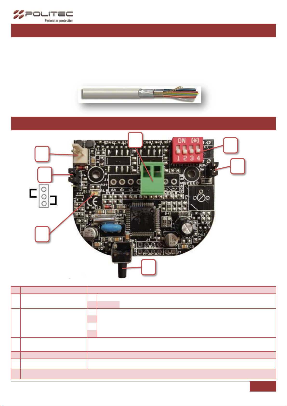
You should also always use cables with screen for alarm connections, proper sizing by taking more
precautions due to electronic devices.
To avoid interfering with the performance and the degree of protection (IP) of the barrier is necessary to
take the necessary precaution, taking care not to alter seals, plastic and mechanical parts of the product,
using original accessories.
In case of repairs covered by warranty (2 years) but with obvious signs of improper installation, the Politec
s.r.l. reserves the right to decide on any repair costs.
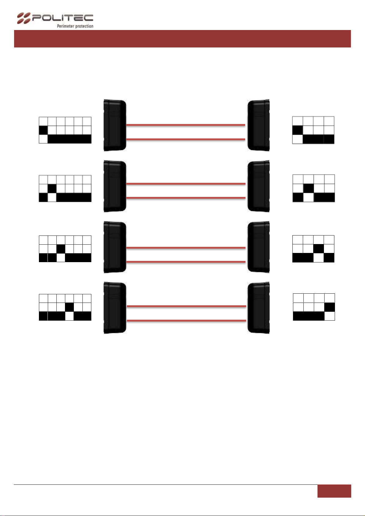
►Avoid installation of receivers beams in a position where are exposed to direct sunlight (with same
angle), especially at sunset and sunrise.
3. INSTALLATION
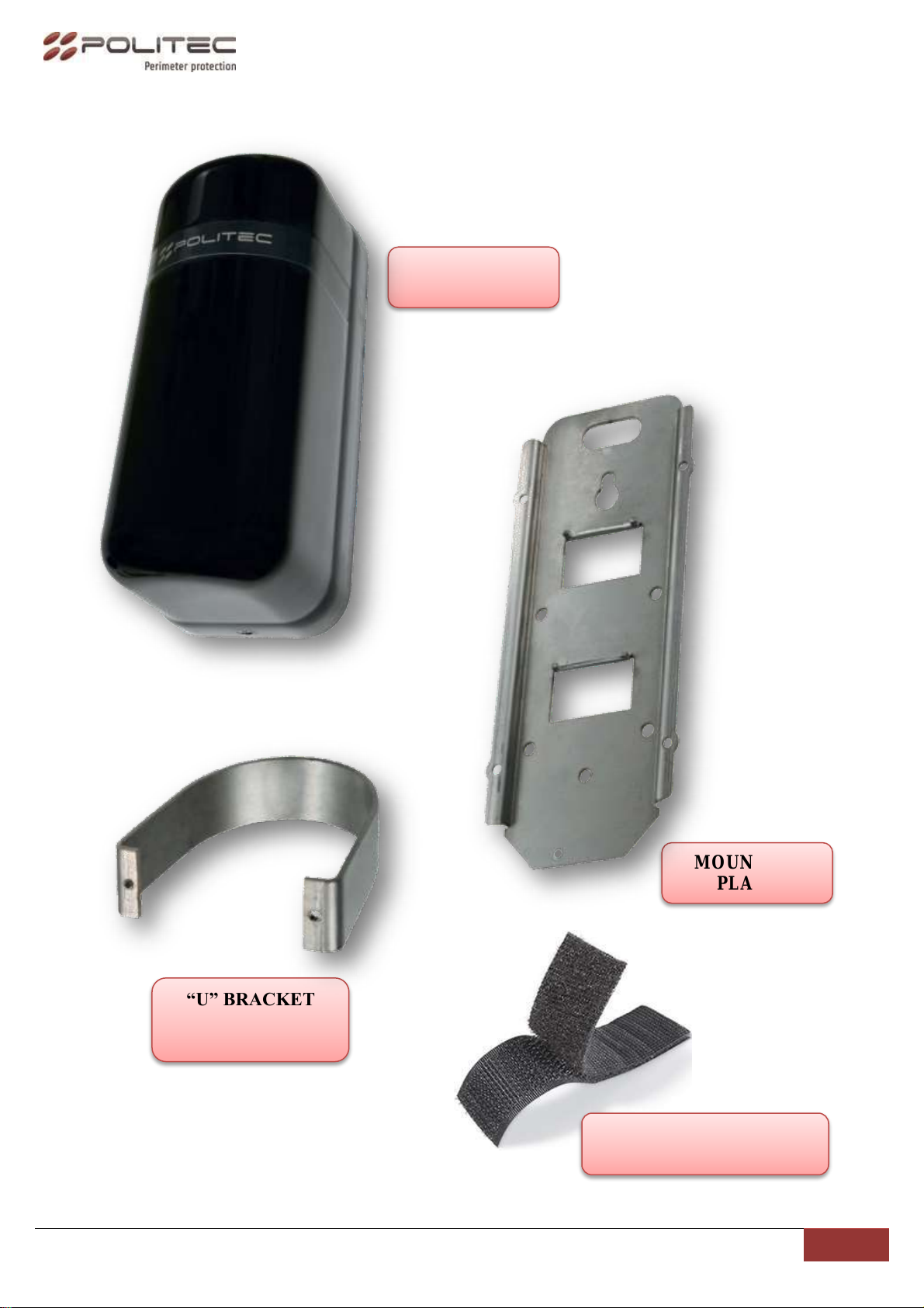
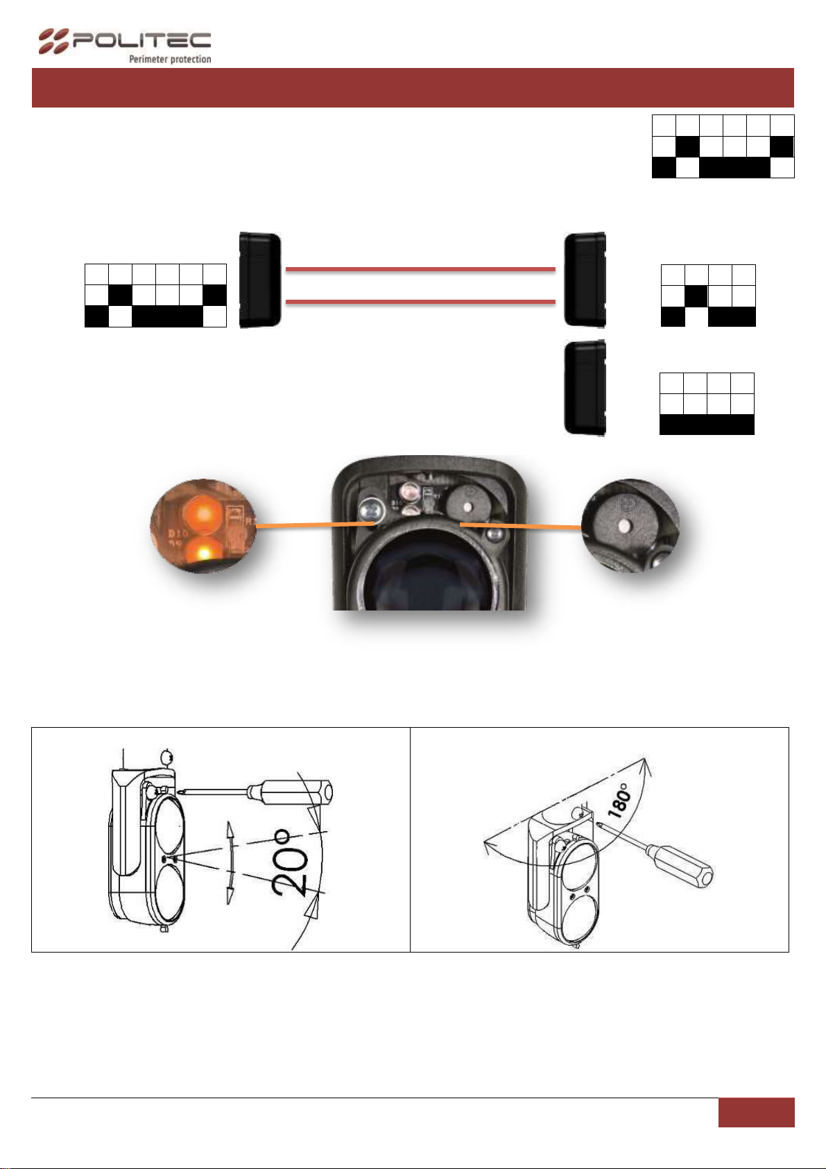
The barrier ALES can be installed to the wall using the mounting plate and the pole using the mounting
plate and the "U" bracket (Pole 48-50).
DEVICE MOUNTING
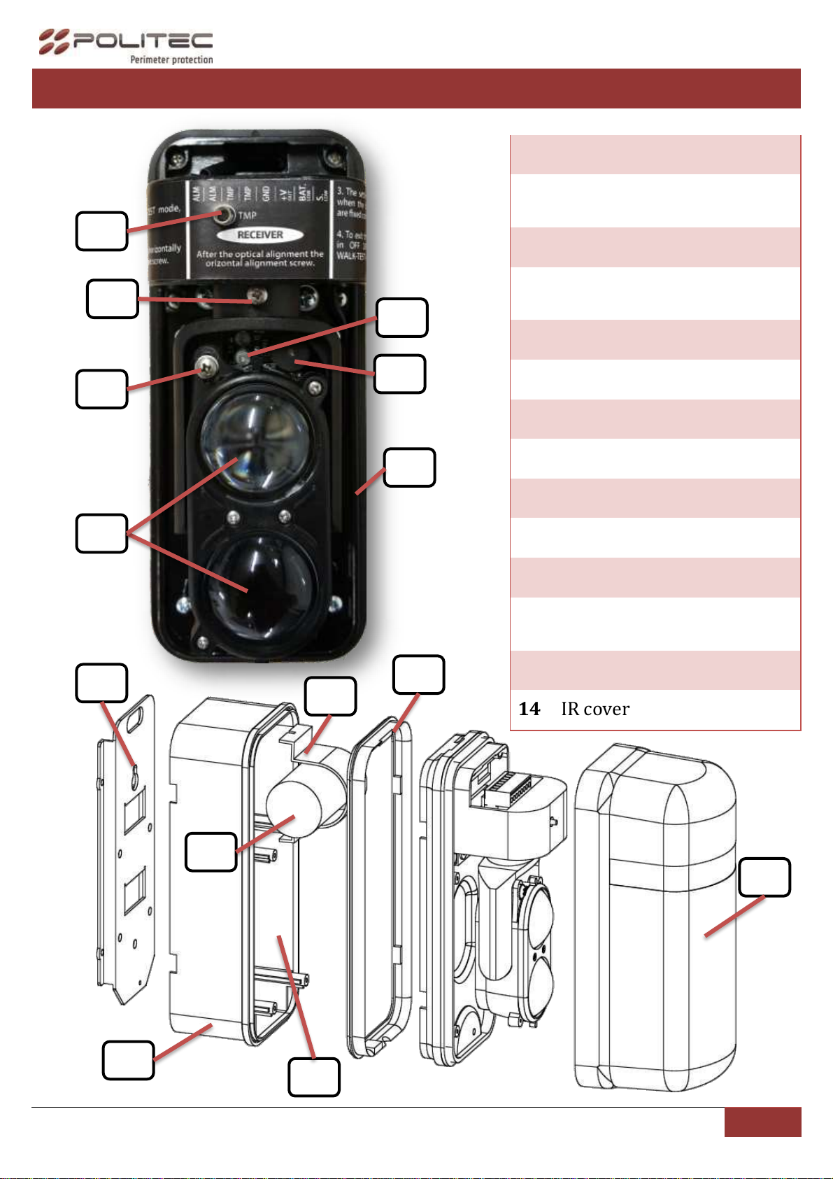
►While opening, pay attention to do not remove completely the screws at optic side, to avoid the
O-ring falling.
1. F ix the mounting plate to the wall (or to pole
using the provided “U” bracket);
2. Insert the insulating gasket on the battery case
and fix it all to the mounting plate,

Politec S.r.l. | Manual ALES WS –Ver. 1.0
6
3. Stick Velcro tape on the radio transmitter and fix
it on the back of the sensor;
4. Connect with proper screened cable the radio
transmitter to the termina block RX (pages 7-8);
5. Insert the power cord into the unit base, through
the hole,
6. Fix unit base on the battery case by tightening
the 4 screws;
7. Connect the power cord into the main board,
paying attention to polarity (BLACK WIRE TO
EXTERNAL SIDE),
8. Hang barrier onto fixed bracket;
9. Fix barrier to bracket tightening screw through
hole under optical and proceed with alignment
of barrier;
10. After alignment procedure and function test
(pages 10-11), replace IR cover and tighten the
under placed screw.
RED
WIRE
BLACK
WIRE

Politec S.r.l. | Manual ALES WS –Ver. 1.0
7
4.CONNECTIONS AND DESCRIPTIONS
To connect radio transmitter to ALES WS main board use a screened cable, connecting also the cable
screen to the GND on terminal board.
►in case of missed connection of cable screen into GND, some disturbs could be injected into the system
causing a bad operability of the product.
5.TRANSMITTER BOARD
1
POWER CONNECTOR
Connection for power cord (batteries 3,6 V –10,8 Ah)
2
TERMINAL BLOCK
1
GND
2
V+=3.6
3
CHANNELS SELECTOR
DIPSWITCH
1
Activate a channel (1 of 4) positioning one dipswitch per time to ON.
►make sure that the same channel is selected on TX and RX.
Positioning all dipswitch of transmitter in OFF, the column
transmission is disabled.
2
3
4
4
TMP1 ADDITIONAL
TAMPER INPUT
Additional tamper input, in case of absence, MUST remain closed by
jumper.
5
TMP
Anti-removal cover tamper.
6
SIGNAL LED
It blinks just at power connection.
7
VOLTAGE CONFIGURATION
6
5
4
3
1
7
3,6 V
3 V
1 2
2

Politec S.r.l. | Manual ALES WS –Ver. 1.0
8
6.RECEIVER BOARD
1
BATTERY INPUT
Connection for power cord (batteries 3,6 V –10,8 Ah)
2
TERMINAL BLOCK
1
ALARM OUTPUT N.C.
2
3
TAMPER OUTPUT
4
5
GND
Output to supply radio transmitter.
6
V+ =3,6V o 3V
7
BATTERY LOWlow battery signal, NC to ground. Opens in case of
low battery.
8
ENVIROMENTAL DISQUALIFICATION: In case of heavy fog, it gives a
negative output signal by an open collector.
3
DIPSWITCH
1
Activate a channel (1 of 4) positioning one dipswitch per time to ON.
►make sure that the same channel is selected on TX and RX.
2
3
4
5
Select ON to deactivate environmental disqualification.
►The barrier, in case of heavy fog or strong condensation on IR cover
(caused by missing of internal thermostat*), enter in disqualification
mode which inhibits alarm output.
6
TEST
4
TMP1 ADDITIONAL
TAMPER INPUT
Tamper input additional, in case of absence MUST remain closed by
jumper
5
ALARM SENSITIVITY ADJUSTMENT (see page 9)
6
TMP
Anti-removal cover tamper.
7
SIGNAL LED
It blinks just at power connection.
8
VOLTAGE CONFIGURATION FOR RADIO TRANSMITTER SUPPLING OUTPUT (3V/3,6V).
7
6
4
3
1
2
8
3,6 V
3 V
1 2 3 4
5 6 7 8
5

Politec S.r.l. | Manual ALES WS –Ver. 1.0
9
7.FREQUENCY SELECTION
To compose barriers or dams with more than one pair of Ales WS, it is necessary to avoid interference assign a
different channel to each of them. To do this you must turn ON dip switches on the desired channel on the
mother board.
►The channel has to be the same from both the transmitter from the receiver
(ex. CH_TX1/CH_RX1 –CH_TX2/CH_RX2 –CH_TX3/CH_RX3 –CH_TX4/CH_RX4).
RX1
1
2
3
4
5
6
ON
TX1
1
2
3
4
ON
RX2
1
2
3
4
5
6
ON
TX2
1
2
3
4
ON
RX3
1
2
3
4
5
6
ON
TX3
1
2
3
4
ON
RX4
1
2
3
4
5
6
ON
TX4
1
2
3
4
ON

Politec S.r.l. | Manual ALES WS –Ver. 1.0
10
8.ALIGNMENT TEST
1. For TEST mode, Set DIP 6 to ON and DIP of desired channel on RX
motherboard.
2. Set DIP to ON of correspondent RX channel on TX motherboard.
►In case of damns, set OFF all other Transmitters, setting OFF channel DIP.
3. After point 1-2, High visibility LED and buzzer (on RX optic) are turned on (if not, consult FAQ)
Align TX optic to RX, vertically and horizontally through adjustment screws to find best alignment possible.
The condition of best alignment is achieved when LEDs are fixed and buzzer sounds continuously. The
condition of partial or total misalignment is indicated by LEDs flashing and low frequency whistle of buzzer.
►Buzzer sounds continuously for max 3 minutes
Vertical adjustment
horizontal adjustment
►To get a good alignment is necessary to make a complete rotation on the optics receiver horizontal axis,
thus effecting the SCANNING of the optical signal.
4. After obtained max signal, tighten horizontal adjustment screw, and exit from TEST mode setting OFF
DIP 6 on RX mother board.
5. WALK-TEST: When DIP 6 is set OFF (after calibration), for 60 second every beam interruption is
associate with a LED flashing and a buzzer sound.
1
2
3
4
5
6
ON
TX2
1
2
3
4
ON
RX1
1
2
3
4
5
6
ON
TX1
1
2
3
4
ON

Politec S.r.l. | Manual ALES WS –Ver. 1.0
11
9.ALARM SENSITIVITYADJUSTMENT
►Making a physical test and operate with potentiometer is possible to adjust beams interruption speed to:
HIGH sensitivity for fast crossing (running); LOW sensitivity for slow crossing (walking).
10. TECHNICALFEATURES
ALES WS
Max range indoors
150m
Max range outdoors
60 m
Synchronization
4 optical channels
Environmental disqualification
Yes, by open collector output
Setting intervention time
50 ms - 500 ms
Power source
8X Battery 3,6 V –19 Ah
Battery life
6 years
Heaters consumption (couple)
Optional (thermostat) 10-30V:
10/15V = 6W, 0.4 A cad.
20/30V = 6W, 0.2 A cad.
Current draw
TX: 300μA RX:350μA
Tamper output
N.C. Relay output (on RX).
Operating temperature
-25° (with heaters) +65°
IP protection
IP65.
Mounting
Indoor/outdoor. Wall/pole/tower.
brackets included for wall/pole
TOTAL WARRANTY 2 YEARS
Adjust potentiometer
counterclockwise to
increase the alarm delay up
to 500ms. In this condition
ensures the alarm of a
person walking through the
barrier, with the advantage
of excluding the possibility
of any false alarms such
animals.
Adjusting the
potentiometer clockwise
to decrease the alarm
delay up to 50ms. In this
condition ensures the
alarm of a person
crossing the barrier
running at maximum
speed.

Politec S.r.l. | Manual ALES WS –Ver. 1.0
12
11. F.A.Q.
I can’t find alignment
oCheck no obstacles are placed between TX and RX and site
conformation not gives itself an obstacle to installation;
oCheck that barriers are supplied and batteries charged;
oMake sure that no other external lights are interesting RX
side, during function TEST (gate photocell, any other
barrier, infrared lights, exc…).
After best signal achieved
(LEDs are fixed and buzzer
sounds continuously) barrier
stays in alarm
oMake sure RX and TX have same channel;
oMake sure that no other external lights are interesting RX
side, during function TEST (gate photocell, any other
barrier, infrared lights, exc…);
oMake sure while Alignment TEST other TX (in case of
dams) are OFF.
System in alarm with fog or
rain
oMake sure environmental disqualification is activated;
oMake sure columns are well closed and check inside there
are no presence of water or insects;
oCheck the precision of alignment and in case remake
alignment TEST, making sure that no other external lights
are interesting RX side (gate photocell, any other barrier,
infrared lights, exc…);
Repeated false alarms
oIf possible, increase the alarm delay up;
oMake sure to have used a correct screened cable and
linked screen to GND of ALES WS motherboard.
Other manuals for ALES WS
1
Table of contents
Other Politec Lighting Equipment manuals
Popular Lighting Equipment manuals by other brands

Pentair
Pentair SAND DOLLAR quick start guide

Future light
Future light DJ-SCAN 200 user manual

Future light
Future light PHB-300E Pro-Head-Beam user manual

Sunlight Supply
Sunlight Supply SUN SYSTEM Series Technical information guide

Lupo
Lupo Smartpanel user manual

NATDIS
NATDIS CleanMove 8 Mounting and operating instructions