ADB Safegate UEL-1-150 User manual

High Intensity Unidirectional Elevated Light for Approach,
Threshold and Runway End and for Sequenced Flashing Lights
(SFLS)
Runway Threshold Identification (RTILS) Systems
User Manual
UM-4020 / AM02-630e, Rev. 2.0, 2020/05/19


A.0 Disclaimer / Standard Warranty
CE certification
The equipment listed as CE certified means that the product complies with the essential requirements concerning safety and
hygiene. The European directives that have been taken into consideration in the design are available on written request to
ADB SAFEGATE.
ETL certification
The equipment listed as ETL certified means that the product complies with the essential requirements concerning safety and
FAA Airfield regulations. The FAA directives that have been taken into consideration in the design are available on written
request to ADB SAFEGATE.
All Products Guarantee
ADB SAFEGATE will correct by repair or replacement per the applicable guarantee above, at its option, equipment or parts
which fail because of mechanical, electrical or physical defects, provided that the goods have been properly handled and
stored prior to installation, properly installed and properly operated after installation, and provided further that Buyer gives
ADB SAFEGATE written notice of such defects after delivery of the goods to Buyer. Refer to the Safety section for more
information on Material Handling Precautions and Storage precautions that must be followed.
ADB SAFEGATE reserves the right to examine goods upon which a claim is made. Said goods must be presented in the same
condition as when the defect therein was discovered. ADB SAFEGATE furthers reserves the right to require the return of such
goods to establish any claim.
ADB SAFEGATE's obligation under this guarantee is limited to making repair or replacement within a reasonable time after
receipt of such written notice and does not include any other costs such as the cost of removal of defective part, installation
of repaired product, labor or consequential damages of any kind, the exclusive remedy being to require such new parts to be
furnished.
ADB SAFEGATE's liability under no circumstances will exceed the contract price of goods claimed to be defective. Any returns
under this guarantee are to be on a transportation charges prepaid basis. For products not manufactured by, but sold by ADB
SAFEGATE, warranty is limited to that extended by the original manufacturer. This is ADB SAFEGATE's sole guarantee and
warranty with respect to the goods; there are no express warranties or warranties of fitness for any particular purpose or any
implied warranties of fitness for any particular purpose or any implied warranties other than those made expressly herein. All
such warranties being expressly disclaimed.
Standard Products Guarantee
Products of ADB SAFEGATE manufacture are guaranteed against mechanical, electrical, and physical defects (excluding lamps)
which may occur during proper and normal use for a period of two years from the date of ex-works delivery, and are
guaranteed to be merchantable and fit for the ordinary purposes for which such products are made.
Note
See your sales order contract for a complete warranty description.
FAA Certified product installed in the United States or in US Military installations guarantee
ADB SAFEGATE L858 Airfield Guidance Signs are warranted against mechanical and physical defects in design or manufacture
for a period of 2 years from date of installation, per FAA AC 150/5345-44 (applicable edition).
ADB SAFEGATE L858(L) Airfield Guidance Signs are warranted against electrical defects in design or manufacture of the LED or
LED specific circuitry for a period of 4 years from date of installation, per FAA EB67 (applicable edition).
ADB SAFEGATE LED light fixtures (with the exception of obstruction lighting) are warranted against electrical defects in design
or manufacture of the LED or LED specific circuitry for a period of 4 years from date of installation, per FAA EB67 (applicable
edition). .
UM-4020 / AM02-630e, Rev. 2.0, 2020/05/19 iii
Copyright © ADB Safegate, All Rights Reserved

Note
See your sales order contract for a complete warranty description.
Liability
WARNING
Use of the equipment in ways other than described in the catalog leaflet and the manual may result in personal injury,
death, or property and equipment damage. Use this equipment only as described in the manual.
ADB SAFEGATE cannot be held responsible for injuries or damages resulting from non-standard, unintended uses of its
equipment. The equipment is designed and intended only for the purpose described in the manual. Uses not described in the
manual are considered unintended uses and may result in serious personal injury, death or property damage.
Unintended uses, includes the following actions:
•Making changes to equipment that have not been recommended or described in this manual or using parts that are not
genuine ADB SAFEGATE replacement parts or accessories.
•Failing to make sure that auxiliary equipment complies with approval agency requirements, local codes, and all applicable
safety standards if not in contradiction with the general rules.
•Using materials or auxiliary equipment that are inappropriate or incompatible with your ADB SAFEGATE equipment.
•Allowing unskilled personnel to perform any task on or with the equipment.
© ADB SAFEGATE BV
This manual or parts thereof may not be reproduced, stored in a retrieval system, or transmitted, in any form or by any means,
electronic, mechanical, photocopying, recording, nor otherwise, without ADB SAFEGATE BV's prior written consent.
This manual could contain technical inaccuracies or typographical errors. ADB SAFEGATE BV reserves the right to revise this
manual from time to time in the contents thereof without obligation of ADB SAFEGATE BV to notify any person of such
revision or change. Details and values given in this manual are average values and have been compiled with care. They are not
binding, however, and ADB SAFEGATE BV disclaims any liability for damages or detriments suffered as a result of reliance on
the information given herein or the use of products, processes or equipment to which this manual refers. No warranty is made
that the use of the information or of the products, processes or equipment to which this manual refers will not infringe any
third party's patents or rights. The information given does not release the buyer from making their own experiments and
tests.
High Intensity Unidirectional Elevated Light for Approach, Threshold and Runway End and for Sequenced Flashing Lights (SFLS)
iv
Copyright © ADB Safegate, All Rights Reserved

TABLE OF CONTENTS
1.0 Safety ....................................................................................................................................................................................... 1
1.1 Safety Messages ........................................................................................................................................................................................................ 1
1.1.1 Introduction to Safety ................................................................................................................................................................................. 2
1.1.2 Intended Use .................................................................................................................................................................................................. 2
1.1.3 Material Handling Precautions: Storage .............................................................................................................................................. 3
1.1.4 Operation Safety ........................................................................................................................................................................................... 3
1.1.5 Maintenance Safety ..................................................................................................................................................................................... 3
1.1.6 Material Handling Precautions, ESD ..................................................................................................................................................... 4
1.1.7 Arc Flash and Electric Shock Hazard ..................................................................................................................................................... 4
2.0 About this Manual ................................................................................................................................................................. 5
3.0 Introduction ............................................................................................................................................................................ 7
3.1 General information ................................................................................................................................................................................................. 7
3.1.1 UEL ..................................................................................................................................................................................................................... 7
3.1.2 Model definition ........................................................................................................................................................................................... 7
3.1.3 Installation ....................................................................................................................................................................................................... 7
3.2 Product data ............................................................................................................................................................................................................... 7
3.2.1 Equipment supplied .................................................................................................................................................................................... 7
3.2.2 UEL dimensions ............................................................................................................................................................................................. 8
3.2.3 Technical data ................................................................................................................................................................................................ 8
3.2.4 References ....................................................................................................................................................................................................... 8
4.0 Installation .............................................................................................................................................................................. 9
4.1 Overview ....................................................................................................................................................................................................................... 9
4.1.1 Introduction .................................................................................................................................................................................................... 9
4.1.2 Mounting methods ...................................................................................................................................................................................... 9
4.2 General recommendations .................................................................................................................................................................................... 9
4.2.1 Receiving, storage and unpacking ......................................................................................................................................................... 9
4.2.2 Electrical connection ................................................................................................................................................................................... 9
4.2.3 Elevation and azimuth setting angles .................................................................................................................................................. 9
4.3 Equipment required for installation ................................................................................................................................................................ 10
4.3.1 Equipment required, but not supplied .............................................................................................................................................. 10
4.4 How to mount the UEL at ground level ......................................................................................................................................................... 10
4.4.1 Introduction ................................................................................................................................................................................................. 10
4.4.2 Procedure ...................................................................................................................................................................................................... 10
4.4.3 Illustration ..................................................................................................................................................................................................... 12
4.5 How to mount the UEL on a 60 mm O.D. conduit ..................................................................................................................................... 12
4.5.1 Introduction ................................................................................................................................................................................................. 12
4.5.2 Procedure ...................................................................................................................................................................................................... 13
4.5.3 Illustration ..................................................................................................................................................................................................... 14
4.6 How to mount the UEL on a safety approach mast .................................................................................................................................. 15
4.6.1 Introduction ................................................................................................................................................................................................. 15
4.6.2 Procedure ...................................................................................................................................................................................................... 15
5.0 Orientation and elevation settings .................................................................................................................................... 19
5.1 Introduction .............................................................................................................................................................................................................. 19
5.2 Standard levelling device ..................................................................................................................................................................................... 19
5.2.1 Introduction ................................................................................................................................................................................................. 19
5.2.2 Procedure ...................................................................................................................................................................................................... 19
5.2.3 Illustration ..................................................................................................................................................................................................... 19
5.3 Electronic leveling device .................................................................................................................................................................................... 20
5.3.1 Introduction ................................................................................................................................................................................................. 20
5.3.2 Composition ................................................................................................................................................................................................ 20
5.3.3 Procedure ...................................................................................................................................................................................................... 20
5.3.4 Illustration ..................................................................................................................................................................................................... 21
5.4 Commissioning ........................................................................................................................................................................................................ 22
UM-4020 / AM02-630e, Rev. 2.0, 2020/05/19 v
Copyright © ADB Safegate, All Rights Reserved

5.4.1 Final check .................................................................................................................................................................................................... 22
6.0 Maintenance ......................................................................................................................................................................... 23
6.1 Overview .................................................................................................................................................................................................................... 23
6.1.1 Introduction ................................................................................................................................................................................................. 23
6.2 Preventive maintenance tasks ........................................................................................................................................................................... 23
6.3 How to replace the lamp ..................................................................................................................................................................................... 24
6.3.1 Procedure ...................................................................................................................................................................................................... 24
6.3.2 Illustration ..................................................................................................................................................................................................... 24
6.4 How to dismantle the optical assembly ........................................................................................................................................................ 25
6.4.1 Procedure ...................................................................................................................................................................................................... 25
6.4.2 Illustration ..................................................................................................................................................................................................... 26
7.0 Troubleshooting ................................................................................................................................................................... 27
8.0 Assemblies and Exploded Views ........................................................................................................................................ 29
8.1 Introduction .............................................................................................................................................................................................................. 29
8.2 Assemblies ................................................................................................................................................................................................................ 29
8.2.1 Spare Parts .................................................................................................................................................................................................... 29
8.2.2 Ordering code UEL .................................................................................................................................................................................... 29
8.2.3 Spare Parts and numbers ........................................................................................................................................................................ 30
8.3 Exploded views ........................................................................................................................................................................................................ 31
8.3.1 UEL-1-150 ..................................................................................................................................................................................................... 31
8.3.2 UEL-1-120 ..................................................................................................................................................................................................... 32
A.0 SUPPORT .............................................................................................................................................................................. 33
A.1 ADB SAFEGATE Website ...................................................................................................................................................................................... 33
A.2 Recycling .................................................................................................................................................................................................................... 33
A.2.1 Local Authority Recycling ....................................................................................................................................................................... 33
A.2.2 ADB SAFEGATE Recycling ....................................................................................................................................................................... 34
High Intensity Unidirectional Elevated Light for Approach, Threshold and Runway End and for Sequenced Flashing Lights (SFLS)
TABLE OF CONTENTS
vi
Copyright © ADB Safegate, All Rights Reserved

1.0 Safety
Introduction to Safety
This section contains general safety instructions for installing and using ADB SAFEGATE equipment. Some safety instructions
may not apply to the equipment in this manual. Task- and equipment-specific warnings are included in other sections of this
manual where appropriate.
1.1 Safety Messages
HAZARD Icons used in the manual
For all HAZARD symbols in use, see the Safety section. All symbols must comply with ISO and ANSI standards.
Carefully read and observe all safety instructions in this manual, which alert you to safety hazards and conditions that may
result in personal injury, death or property and equipment damage and are accompanied by the symbol shown below.
WARNING
Failure to observe a warning may result in personal injury, death or equipment damage.
DANGER - Risk of electrical shock or ARC FLASH
Disconnect equipment from line voltage. Failure to observe this warning may result in personal injury, death, or
equipment damage. ARC Flash may cause blindness, severe burns or death.
WARNING - Wear personal protective equipment
Failure to observe may result in serious injury.
WARNING - Do not touch
Failure to observe this warning may result in personal injury, death, or equipment damage.
CAUTION
Failure to observe a caution may result in equipment damage.
Qualified Personnel
Important Information
The term qualified personnel is defined here as individuals who thoroughly understand the equipment and its safe
operation, maintenance and repair. Qualified personnel are physically capable of performing the required tasks, familiar
with all relevant safety rules and regulations and have been trained to safely install, operate, maintain and repair the
equipment. It is the responsibility of the company operating this equipment to ensure that its personnel meet these
requirements.
Always use required personal protective equipment (PPE) and follow safe electrical work practice.
UM-4020 / AM02-630e, Rev. 2.0, 2020/05/19 1
Copyright © ADB Safegate, All Rights Reserved
1.1.1 Introduction to Safety
CAUTION
Unsafe Equipment Use
This equipment may contain electrostatic devices, hazardous voltages and sharp edges on components
• Read installation instructions in their entirety before starting installation.
• Become familiar with the general safety instructions in this section of the manual before installing,
operating, maintaining or repairing this equipment.
• Read and carefully follow the instructions throughout this manual for performing specific tasks and
working with specific equipment.
• Make this manual available to personnel installing, operating, maintaining or repairing this
equipment.
• Follow all applicable safety procedures required by your company, industry standards and
government or other regulatory agencies.
• Install all electrical connections to local code.
• Use only electrical wire of sufficient gauge and insulation to handle the rated current demand. All
wiring must meet local codes.
• Route electrical wiring along a protected path. Make sure they will not be damaged by moving
equipment.
• Protect components from damage, wear, and harsh environment conditions.
• Allow ample room for maintenance, panel accessibility, and cover removal.
• Protect equipment with safety devices as specified by applicable safety regulations
• If safety devices must be removed for installation, install them immediately after the work is
completed and check them for proper functioning prior to returning power to the circuit.
Failure to follow this instruction can result in serious injury or equipment damage
Additional Reference Materials
Important Information
•IEC - International Standards and Conformity Assessment for all electrical, electronic and related technologies.
•IEC 60364 - Electrical Installations in Buildings.
•FAA Advisory: AC 150/5340-26 (current edition), Maintenance of Airport Visual Aid Facilities.
•Maintenance personnel must refer to the maintenance procedure described in the ICAO Airport Services Manual,
Part 9.
•ANSI/NFPA 79, Electrical Standards for Metalworking Machine Tools.
•National and local electrical codes and standards.
1.1.2 Intended Use
CAUTION
Use this equipment as intended by the manufacturer
This equipment is designed to perform a specific function, do not use this equipment for other purposes
• Using this equipment in ways other than described in this manual may result in personal injury, death
or property and equipment damage. Use this equipment only as described in this manual.
Failure to follow this instruction can result in serious injury or equipment damage
High Intensity Unidirectional Elevated Light for Approach, Threshold and Runway End and for Sequenced Flashing Lights (SFLS)
Safety
2
Copyright © ADB Safegate, All Rights Reserved
1.1.3 Material Handling Precautions: Storage
CAUTION
Improper Storage
Store this equipment properly
• If equipment is to be stored prior to installation, it must be protected from the weather and kept free
of condensation and dust.
Failure to follow this instruction can result in equipment damage
1.1.4 Operation Safety
CAUTION
Improper Operation
Do Not Operate this equipment other than as specified by the manufacturer
• Only qualified personnel, physically capable of operating the equipment and with no impairments in
their judgment or reaction times, should operate this equipment.
• Read all system component manuals before operating this equipment. A thorough understanding of
system components and their operation will help you operate the system safely and efficiently.
• Before starting this equipment, check all safety interlocks, fire-detection systems, and protective
devices such as panels and covers. Make sure all devices are fully functional. Do not operate the
system if these devices are not working properly. Do not deactivate or bypass automatic safety
interlocks or locked-out electrical disconnects or pneumatic valves.
• Protect equipment with safety devices as specified by applicable safety regulations.
• If safety devices must be removed for installation, install them immediately after the work is
completed and check them for proper functioning.
• Route electrical wiring along a protected path. Make sure they will not be damaged by moving
equipment.
• Never operate equipment with a known malfunction.
• Do not attempt to operate or service electrical equipment if standing water is present.
• Use this equipment only in the environments for which it is rated. Do not operate this equipment in
humid, flammable, or explosive environments unless it has been rated for safe operation in these
environments.
• Never touch exposed electrical connections on equipment while the power is ON.
Failure to follow these instructions can result in equipment damage
1.1.5 Maintenance Safety
DANGER
Electric Shock Hazard
This equipment may contain electrostatic devices
• Do not operate a system that contains malfunctioning components. If a component malfunctions,
turn the system OFF immediately.
• Disconnect and lock out electrical power.
• Allow only qualified personnel to make repairs. Repair or replace the malfunctioning component
according to instructions provided in its manual.
Failure to follow these instructions can result in death or equipment damage
UM-4020 / AM02-630e, Rev. 2.0, 2020/05/19 3
Copyright © ADB Safegate, All Rights Reserved

1.1.6 Material Handling Precautions, ESD
CAUTION
Electrostatic Sensitive Devices
This equipment may contain electrostatic devices
• Protect from electrostatic discharge.
• Electronic modules and components should be touched only when this is unavoidable e.g. soldering,
replacement.
• Before touching any component of the cabinet you shall bring your body to the same potential as the
cabinet by touching a conductive earthed part of the cabinet.
• Electronic modules or components must not be brought in contact with highly insulating materials
such as plastic sheets, synthetic fiber clothing. They must be laid down on conductive surfaces.
• The tip of the soldering iron must be grounded.
• Electronic modules and components must be stored and transported in conductive packing.
Failure to follow this instruction can result in equipment damage
1.1.7 Arc Flash and Electric Shock Hazard
DANGER
Series Circuits have Hazardous Voltages
This equipment produces high voltages to maintain the specified current - Do NOT Disconnect while
energized.
• Allow only qualified personnel to perform maintenance, troubleshooting, and repair tasks.
• Only persons who are properly trained and familiar with ADB SAFEGATE equipment are permitted to
service this equipment.
• An open airfield current circuit is capable of generating >5000 Vac and may appear OFF to a meter.
• Never unplug a device from a constant current circuit while it is operating; Arc flash may result.
• Disconnect and lock out electrical power.
• Always use safety devices when working on this equipment.
• Follow the recommended maintenance procedures in the product manuals.
• Do not service or adjust any equipment unless another person trained in first aid and CPR is present.
• Connect all disconnected equipment ground cables and wires after servicing equipment. Ground all
conductive equipment.
• Use only approved ADB SAFEGATE replacement parts. Using unapproved parts or making
unapproved modifications to equipment may void agency approvals and create safety hazards.
• Check the interlock systems periodically to ensure their effectiveness.
• Do not attempt to service electrical equipment if standing water is present. Use caution when
servicing electrical equipment in a high-humidity environment.
• Use tools with insulated handles when working with airfield electrical equipment.
Failure to follow these instructions can result in death or equipment damage
High Intensity Unidirectional Elevated Light for Approach, Threshold and Runway End and for Sequenced Flashing Lights (SFLS)
Safety
4
Copyright © ADB Safegate, All Rights Reserved

2.0 About this Manual
This manual describes the procedures for installation, maintenance and troubleshooting of the ADB SAFEGATE type UEL
lights.
This manual covers the light fixtures suitable for use in systems described in ICAO Annex 14, Attachment A, Section 11 .
The light construction is in compliance with FAA E 982 specification for the general functional constructional requirements,
and with AC150/5345-46B for mechanical & environmental properties.
This light also complies with NATO STANAG 3316.
Operation beyond the limitations mentioned in those specifications may result in degradation of performance, damage or
failure of components or hazardous conditions.
For more information, see www.adbsafegate.com.
UM-4020 / AM02-630e, Rev. 2.0, 2020/05/19 5
Copyright © ADB Safegate, All Rights Reserved

High Intensity Unidirectional Elevated Light for Approach, Threshold and Runway End and for Sequenced Flashing Lights (SFLS)
About this Manual
6
Copyright © ADB Safegate, All Rights Reserved
3.0 Introduction
3.1 General information
3.1.1 UEL
The UEL-1-150 steady burning lights are used for:
•Precision Approach lighting in Cat. I, II and III in white and red light,
•Threshold and Threshold wingbar lighting in Cat. I, II and III in green light,
•Runway end lighting in Cat. I, II and III in red light,
•Supplementary elevated stopbar lights.
The UEL-1-120 flashing lights are used for:
•Sequence Flashing Lights (SFLS) or Runway Threshold Identification Lights (RTILS), using a low voltage (400V) Xenon flash
lamp.
3.1.2 Model definition
•The UEL-1-150 is a steady burning unidirectional elevated light.
•The UEL-1-120 is a flashing unidirectional elevated light used in a flashing system in combination with the control
cabinets FCU.
Note
Refer to the exploded views, see § Exploded views.
3.1.3 Installation
They are shipped ready for installation and can be mounted in three different ways, on any support with a 60 mm outer
diameter mounting interface:
•At ground level
•On a 60 mm O.D. conduit
•On a safety approach mast
3.2 Product data
3.2.1 Equipment supplied
UEL units are either packed individually in a durable, cushioned and corrugated cardboard box, labeled with ADB SAFEGATE
and ordering numbers, or on pallet boxes in larger quantities.
UM-4020 / AM02-630e, Rev. 2.0, 2020/05/19 7
Copyright © ADB Safegate, All Rights Reserved

Depending on the ordered code number, the fittings are supplied:
•With lamp (packed separately)
•With or without power supply cable cable (packed separately)
•With or without top light, see § Exploded views
Unless contractually specified differently, one instruction manual is delivered per order.
3.2.2 UEL dimensions
The illustration below gives you the outside dimensions of the UEL light, in mm.
3.2.3 Technical data
The table below lists technical data of the UEL.
Type UEL-1-150 UEL-1-120
Input 6.6 A 400 V (through FCU cabinet)
Rated lamp life 1000 hours 3.600.000 flashes
Temperature range - 55°C to + 55°C - 55°C to + 55°C
Humidity up to 100% up to 100%
Protection class IP 44 IP 44
Altitude Sea level to 3000 m Sea level to 3000 m
Wind Velocities up to 560 km/hr Velocities up to 560 km/hr
Weight Approx. 1.7 kg Approx. 2.0 kg
3.2.4 References
Note
For ordering codes and reference data pertinent to the product, see § Spare Parts .
High Intensity Unidirectional Elevated Light for Approach, Threshold and Runway End and for Sequenced Flashing Lights (SFLS)
Introduction
8
Copyright © ADB Safegate, All Rights Reserved

4.0 Installation
4.1 Overview
4.1.1 Introduction
This chapter instructs you on how to install the UEL lights.
Generally, the installation complies with the applicable sections in the ICAO Aerodrome Design Manual, part 4, FAA Advisory
Circulars and, if applicable, other National Codes or local rules.
4.1.2 Mounting methods
The UEL can be mounted in three different ways, on any support with a 60 mm outer diameter mounting interface:
•At ground level
•On a 60 mm O.D. conduit
•On a safety approach mast
4.2 General recommendations
4.2.1 Receiving, storage and unpacking
1. Upon receipt of goods at the site store, check all packages for visible damage. Every damaged box should be opened and
its content inspected for damage.
Note
If equipment is damaged, a claim form shall be filed with the carrier immediately. It may then be necessary for the
carrier to inspect the equipment.
2. Store the light assembly preferably in its original packing in a protected area. When stored unpacked, please take care not
to damage the cable insulation.
3. Unpack the light assembly at the installation site to avoid damage during transportation and handling.
4.2.2 Electrical connection
•The UEL-1-150 light assemblies are designed for connection to 6.6 or 20 Amps series circuits via one FAA L-830 or L-831
isolation transformer (type ADB : RST), with a nominal secondary current of 6,6A.
Refer to ADB cat. leaflet A.06.110 or Instruction manual AM.06.110 for more information on isolation transformers.
The isolation transformers are to be ordered separately.
•The UEL-1-120 light assemblies are designed for connection to a FCU control cabinet by means of a 5-core cable.
Refer to ADB Instruction Manual A.02.6200 for more information on the connection to the FCU control cabinet and the
type of cable to use.The FCU control cabinets are to be ordered separately.
4.2.3 Elevation and azimuth setting angles
Elevation and azimuth setting angles according to the specific use and location of the light can be found in ICAO Annex 14,
Appendix 2, Fig. 2.1 to 2.4 and 2.8.
Note
For instructions about how to set the elevation angle, see § Orientation and elevation settings .
UM-4020 / AM02-630e, Rev. 2.0, 2020/05/19 9
Copyright © ADB Safegate, All Rights Reserved

4.3 Equipment required for installation
4.3.1 Equipment required, but not supplied
In the table below you will find a list of the equipment required for installation, but not supplied with the lights:
Description CN Quantity
L-867 base plate assembly and gasket (if base mounted) see cat.leaf. A/R
L-867 deep base (if base mounted) see cat.leaf. A/R
Conduit elbow (if mounted on conduit elbow) 1409.00.012 A/R
Breakable coupling MR/F2 for mounting on 60mm O.D. conduit 1409.05.027 A/R
Breakable coupling for ground mounting 1409.06.020 A/R
2-core cable with factory-moulded FAA L-823 plug - 1/light
Primary connector kit, 1-pole - 1/light
Secondary connector kit, 2-pole - 1/light
Natural hydraulic vacuum silicone grease 7850.42.210 A/R
Scotch N° 33 electrical tape 7637.55.123 A/R
Standard leveling device 1570.05.410 A/R
Electronic leveling device 1570.05.400 A/R
CN = Order Number
A/R = As requested
Notes
*= supplied with some versions of the UEL
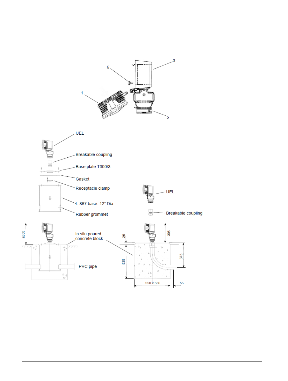
4.4 How to mount the UEL at ground level
4.4.1 Introduction
The UEL is mounted on a breakable coupling which is screwed into a mounting device such as a conduit elbow or a deep
base with cover.
4.4.2 Procedure
1. UEL-1-150 steady burning light
High Intensity Unidirectional Elevated Light for Approach, Threshold and Runway End and for Sequenced Flashing Lights (SFLS)
Installation
10
Copyright © ADB Safegate, All Rights Reserved

The following table instructs you on how to install the UEL-1-150 at ground level:
a) Before installing the light, connect the plug of the two-core cable to the receptacle of the cable coming from the
transformer.
Note
The transformer receptacle rests in the upper part of the conduit elbow or the cover plate.
CAUTION
Do not tape the plug/receptacle assembly in order to allow for quick disconnection in case of impact.
b) Screw the breakable coupling in the conduit elbow or cover plate.
c) Remove the optical cartridge (1) by hinging it down and lifting it out of the hinge.
Insert the two-core cable through the housing (3), and install the light without optical cartridge on the breakable
coupling, without tightening the bracing clamp (5).
d) Clamp the cable into the stress reliever (6).
Note
In case of a top light, the two cables should be clamped into the cable stress reliever.
e) Cut the two-core cable in the light fitting to the right length, maintaining sufficient slack to easily connect it to the
lamp with the cartridge hinged down.
Crimp the "fast-on" connectors on the cores of the cable.
Slip the insulation sleeves over the cores of the cable.
f) Adjust the position of the light unit, see § Orientation and elevation settings .
g) Once the position of the light is correct, put the optical cartridge back in place.
h) Connect the lamp to the fast-on connectors.
CAUTION
To avoid short-circuits, make sure to slip the insulation sleeves over the fast-on connectors.
i) Close the light fitting.
2. UEL-1-120 flashing light
The following table instructs you on how to install the UEL-1-120 at ground level:
a) Before installing the light, make sure that a sufficient length of of 5-core cable coming from the FCU cabinet is
available above the conduit elbow or the cover plate.
b) Install the breakable coupling on the conduit elbow or cover plate.
c) Remove the optical cartridge (1) by hinging it down, disconnecting the lamp connector and lifting the cartridge out of
the hinge.
Insert the cable through the housing (3), and install the light without optical cartridge on the breakable coupling,
without tightening the bracing clamp (5).
d) Clamp the cable into the stress reliever (6).
e) Cut the cable in the light fitting to the right length, maintaining sufficient slack to easily connect the cable to the
connector.
Connect the cable to the connector.
f) Adjust the position of the light unit, see § Orientation and elevation settings .
g) Once the position of the light is correct, put the optical cartridge back in place.
UM-4020 / AM02-630e, Rev. 2.0, 2020/05/19 11
Copyright © ADB Safegate, All Rights Reserved
h) Insert the lamp connector back in place.
i) Close the light fitting.
4.4.3 Illustration
The illustration below gives an overview of the procedure described above.
4.5 How to mount the UEL on a 60 mm O.D. conduit
4.5.1 Introduction
The UEL is mounted on a piece of aluminum conduit with 60 mm O.D, with a maximum length of 2 meters. The conduit is
fastened in a breakable coupling, which in turn is screwed into a conduit elbow or on a base cover.
High Intensity Unidirectional Elevated Light for Approach, Threshold and Runway End and for Sequenced Flashing Lights (SFLS)
Installation
12
Copyright © ADB Safegate, All Rights Reserved

4.5.2 Procedure
1. UEL-1-150 steady burning light
The following table instructs you on how to install the UEL-1-150 on a 60 mm O.D. conduit:
a) Before installing the light, prepare a two-core cable with plug, making sure that a sufficient length of cable is available
above the conduit elbow or cover plate. Connect the plug of the two-core cable to the receptacle of the cable coming
from the transformer.
Note
The transformer receptacle rests in the upper part of the conduit elbow or the cover plate.
CAUTION
Do not tape the plug/receptacle assembly in order to allow for quick disconnection in case of impact.
b) Install the breakable coupling on the conduit elbow or cover plate, and the conduit on the breakable coupling.
CAUTION
Make sure that the conduit is perfectly vertical, using the screws of the breakable coupling for adjustment.
Tighten the counter-nuts.
c) Remove the optical cartridge (1) by hinging it down and lifting it out of the hinge.
Insert the two-core cable through the housing (3), and install the light without optical cartridge on the conduit,
without tightening the bracing clamp (5).
d) Clamp the cable into the stress reliever (6).
Note
In case of a top light, the two cables should be clamped into the cable stress reliever.
e) Cut the two-core cable in the light fitting to the right length, maintaining sufficient slack to easily connect it to the
lamp with the cartridge hinged down.
Crimp the "fast-on" connectors on the cores of the cable.
Slip the insulation sleeves over the cores of the cable.
f) Adjust the position of the light unit, see § Orientation and elevation settings .
g) Once the position of the light is correct, put the optical cartridge back in place.
h) Connect the lamp to the fast-on connectors.
CAUTION
To avoid short-circuits, make sure to slip the insulation sleeves over the fast-on connectors.
i) Close the light fitting.
2. UEL-1-120 flashing light
The following table instructs you on how to install the UEL-1-120 on a 60 mm O.D. conduit:
a) Before installing the light, make sure that a sufficient length of 5-core cable coming from the FCU cabinet is available
above the conduit elbow.
b) Install the breakable coupling on the conduit elbow or cover plate, and the conduit on the breakable coupling.
WARNING
The conduit must be perfectly vertical, using the screws of the breakable coupling for adjustment. Tighten the
counter-nuts.
UM-4020 / AM02-630e, Rev. 2.0, 2020/05/19 13
Copyright © ADB Safegate, All Rights Reserved
c) Remove the optical cartridge (1) by hinging it down, disconnecting the lamp connector and lifting the cartridge out of
the hinge.
Insert the cable through the housing (3), and install the light without optical cartridge on the conduit, without
tightening the bracing clamp (5).
d) Clamp the cable into the stress reliever (6).
e) Cut the cable in the light fitting to the right length, maintaining sufficient slack to easily connect the cable to the
connector.
Connect the cable to the connector.
f) Adjust the position of the light unit, see § Orientation and elevation settings .
g) Once the position of the light is correct, put the optical cartridge back in place.
h) Insert the lamp connector back in place.
i) Close the light fitting.
4.5.3 Illustration
The illustration below gives an overview of the procedure described above.
High Intensity Unidirectional Elevated Light for Approach, Threshold and Runway End and for Sequenced Flashing Lights (SFLS)
Installation
14
Copyright © ADB Safegate, All Rights Reserved
This manual suits for next models
1
Table of contents
Other ADB Safegate Lighting Equipment manuals

ADB Safegate
ADB Safegate AXON User manual

ADB Safegate
ADB Safegate RELIANCE Intelligent Lighting Platform III User manual

ADB Safegate
ADB Safegate RELIANCE L-810 OBSL-L User manual

ADB Safegate
ADB Safegate RELIANCE Omni 1-Dome User manual

ADB Safegate
ADB Safegate RELIANCE Series User manual

ADB Safegate
ADB Safegate RELIANCE User manual

ADB Safegate
ADB Safegate AXON FAA L-852AL User manual

ADB Safegate
ADB Safegate REIL-L User manual

ADB Safegate
ADB Safegate L-858 AGSF Series User manual

ADB Safegate
ADB Safegate L-862E User manual


