Politec SANDOR DUAL SMA User manual

DUAL OPTICS
INSTALLATION MAUAL

POLITEC s.r.l. | Sandor Dual Sma manual – Ver. 2.4 2
INDEX
1COMPONENTSPag.3
2MOUNTINGEXAMPLEPag.4
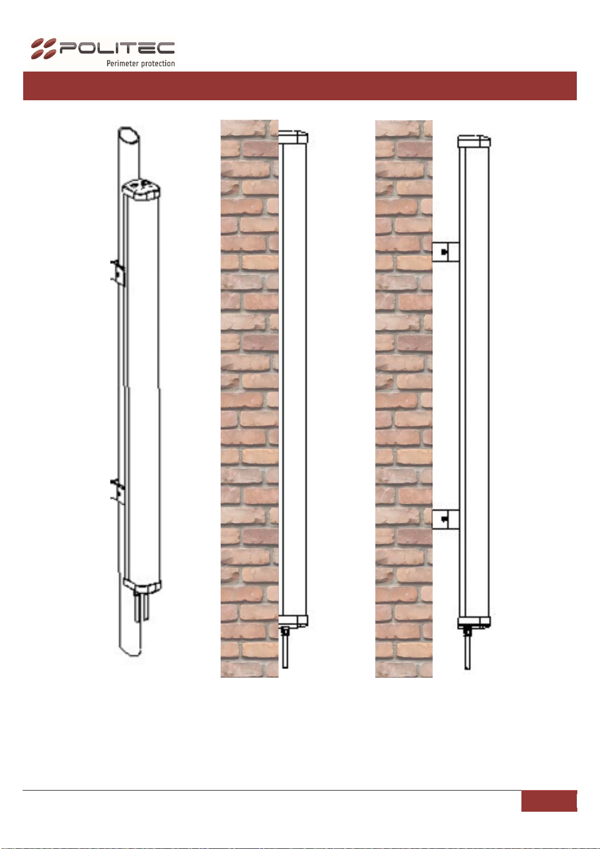
MOUNTINGWITHBRACKETS Pag.5
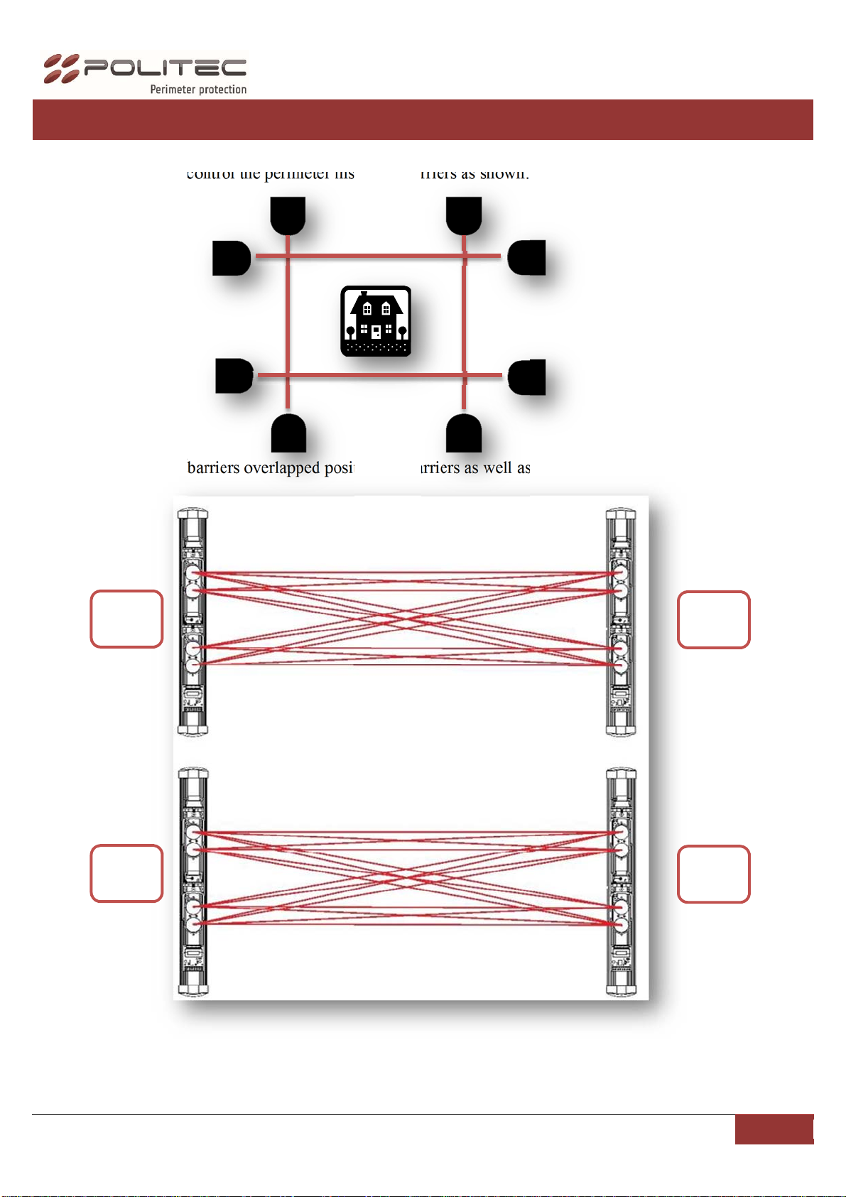
3INSTALLATIONEXAMPLESPag.6
4CABLEANDCABLINGPag.7
CONNECTION AND HEATING SETTING Pag.8
5OPTICALCONFIGURATIONPag.9
TXOPTICAL Pag.9
RXOPTICAL Pag.10
6COLUMNALIGNEMENTPag.11
7CALIBRATIONTHRUSMASYSTEMPag.12
8CALIBRATIONWITHPARALLELBEAMSPag.15
9CALIBRATIONWITHCROSSINGBEAMSPag.16
10SETTINGSANDPROGRAMMINGSCHEDADUALTXPag.17
DIPSWITCHESDESCRIPTION Pag.18
CONNECTORDESCRIPTION&FUNCTIONALITY Pag.18
11SETTINGSANDPROGRAMMINGDUALRXPag.19
DESCRIPTIONDIPSWITCHES Pag.20
RESPONSETIMESETTINGS Pag.20
LEDDESCRIPTION Pag.21
CONNECTORDESCRIPTION&FUNCTIONALITY Pag.21
12TECHNICALCHARATTERISTICSPag.22
Installation recommendation
Verify that the beam tower is fully watertight once the cover and end caps have been correctly filled at the
end of the installation.
Use the cable glands supplied on the tower for all cabling must pass through the lower end cap using the
cable glands supplied. The missed used of proper accessories decrease the IP grade protection of the
tower.
Avoid any type of obstruction between the transmitter and receiver.
Avoid installing the receivers beams in a position where direct sunlight, at the same angle as the receivers
beams, can enter directly into optics especially at sunset and sunrise
Do not install multiple beams where the transmitter beam can interfere with other receiver beams. It is
always better place either transmitter or receivers back to back.

POLITEC s.r.l. | Sandor Dual Sma manual – Ver. 2.4 3
1MAIN COMPONENTS LIST
DESCRIPTION
1Aluminiumprofile
2Plasticprofile
3Caps
4OpticalsRX/TX
5Flatcable
6Motherboard
1
2
3
4
6

POLITEC s.r.l. | Sandor Dual Sma manual – Ver. 2.4 4
2MOUNTING SAMPLES
Pole
mounting
with
SAN/PL
Wall
mounting
with
SAN/SD
Wall
mounting
with
SAN/PL

POLITEC s.r.l. | Sandor Dual Sma manual – Ver. 2.4 5
MOUNTING WITH BRACKETS
N.B.: è consigliato l’utilizzo delle staffe SAN/PL a parete quando si effettua la protezione di varchi
(finestre, porte, …) lungo la parete, onde evitare piccoli ostacoli (cerniere, bordi dei davanzali, …)
che potrebbero trovarsi tra i raggi creando un’attenuazione del segnale.
Insert the bracket
on the back
Wall mounting with
SAN/PL
Pole
mounting
with
SAN/PL
Diameter pole
max 48 mm
Wall mounting with
SAN/SD

POLITEC s.r.l. | Sandor Dual Sma manual – Ver. 2.4 6
3INSTALLATION SAMPLES
For an installation to control the perimeter install the barriers as shown:
For an installation of barriers overlapped position the barriers as well as in the figure:
TX
RX
RX
TX

POLITEC s.r.l. | Sandor Dual Sma manual – Ver. 2.4 7
4CABLES AND WIRING
The wiring requires to SEPARATE the power cable 12Vdc (ex. 2x0.5 + Nx0.22),to the power
cable for heaters 24Vac (ex. 2x0.75) to prevent input of disorders of the AC voltage on the
barrier.
N.B. is absolutely necessary to shield the cable that provides 12 Vdc power supply and put
the metal braid to ground.
The cable size depends on the consumption of the columns and the resistance of the cable to the distances
involved.
The table shows the cable sections and the relative distances to which they provide optimum performance using
the supplier LAR22 (12Vdc - 2,5A / 24V AC-300W) and a barrier SANDOR DUAL SMA.
Cablesection12Vdc24Vac
0,5mm² 165m 35m
0,75mm² 245m 50m
1,5mm² 490m 100m
2,5mm² 820m 165m
4mm² 1310m 265m
6mm² 1975m 400m
N.B. THE LAR22 IS NOT WATERPROOF, MUST BE PLACED INSIDE A LOCAL OR PLACED IN
A SEALED CONTAINER FOR USE OUTSIDE.
Is possible use the power supplier LAR18 (12Vdc – 0,9A / 24VAC-60W) to supply a single column.

POLITEC s.r.l. | Sandor Dual Sma manual – Ver. 2.4 8
CONNECTION AND HEATING SETTING
The power of the heaters is by default set to 24 Vac, but you can set it to 12 Vdc repositioning the jumper on
both RX and TX mother boards and on each optical as shown.
24V
12V
MOTHER
BOARD
24V
OPTICAL
12V

POLITEC s.r.l. | Sandor Dual Sma manual – Ver. 2.4 9
5OPTICAL CONFIGURATION
TX OPTICAL
1234567 123456
TX1
TX2
To test the functionality of optics TX put ON the DIP 7 and see the activation of the power LED. Set SW4 to
supply of the heaters. 24V (standard) or 12V. The voltage can be AC or DC.
NB: The settings relating to addresses are already set to Default.
24V
12V
HEATHER SUPPLY
POWER LED
TAMPER
LED
TEST

POLITEC s.r.l. | Sandor Dual Sma manual – Ver. 2.4 10
RX OPTICAL
1234567 123456
RX1
RX2
To test the functionality of optics TX put ON the DIP 7 and see the activation of the power LED. Set SW4 to
supply of the heaters. 24V (standard) or 12V. The voltage can be AC or DC.
In the J4 jumper reads the value of the signal in volts.
NB: The settings relating to addresses are already set to Default.
24V
12V
HEATER SUPPLY
TEST SIGNAL POINT
TAMPER
SIGNAL
LOW LED
LED
TEST

POLITEC s.r.l. | Sandor Dual Sma manual – Ver. 2.4 11
6.COLUMN ALIGNEMENT
For proper alignment, once the barriers are installed, orient the optical of transmitters and receivers in the
direction of each other by adjusting the lens holder horizontally through the manual movement after loosening
the locking screw on the joint, and vertically through the front screw on the left side of the lens.
Vertical adjustment
Horizontal adjustment
N.B.: FASTEN THE UNLOCKING SCREW AFTER THE ADJUSTMENT
SCREW

POLITEC s.r.l. | Sandor Dual Sma manual – Ver. 2.4 12
7CALIBRATION THROUGH SMA SYSTEM
You can improve the calibration by using of the supplied filter
1)
Bend the device according to the preset bends
2)
Place the filter in front of the optics TX placing the two hooks on the pins of the fork optics to improve
the search for the signal alignment with critical conditions.
You simply apply the filter only on the TX, it is not necessary to repeat the operation on the RX too.

POLITEC s.r.l. | Sandor Dual Sma manual – Ver. 2.4 13
3)
Start the alignment of the transmitter is on the barrier by checking the position of the DIP switch 7 to
ON and activating the TEST optics TX (1 or 2 or 3 or 4), by pressing the dedicated button for about 3
seconds until the orange LED TEST will lit up.
4)
Place in the corresponding optical TEST (1 or 2 or 3 or 4) on coral receiver, checking the position of the
DIP switch 7 to ON and pressing the dedicated button for 3 seconds until the the BUZZER and the LED
TEST turns ON, (with high brightness)
5)
Through the TRANSMITTER lens shifts, find the maximum optical alignment based on the Buzzer and
LEDs (with high brightness), the increase in the frequency of flashing (until the LEDs is fix on and the
whistle of the corresponding BUZZER) indicate a better ALIGNMENT.
TEST
BUTTON
DIP 7 ON
TEST
BUTTON
DIP 7 ON
ORANGE
LED
ORANGE
LED
DIP 7 ON
TO ACTIVATE
THE LED
DIP 7 ON
TO ACTIVATE
THE LED

POLITEC s.r.l. | Sandor Dual Sma manual – Ver. 2.4 14
6)
With a FULL rotation on the horizontal RX lens, is carried out the SCANNING of the optical signal.
7)
Rotating the lens RX find the maximum value of ALIGNMENT corresponding to the LEDs (with high
brightness) FIXED and the whistle of the BUZZER CONTINUOUS.
8)
Exit the function of by repressing the ALIGNMENT TEST button for about 3 seconds on both optics
(TX-RX) making sure that the orange LED TEST is shown in original condition.
9)
When finishedremove the shade disk that acts as a attenuator, having the certainty of having found the
optimum value.
TEST
BUTTON
ORANGE
LED

POLITEC s.r.l. | Sandor Dual Sma manual – Ver. 2.4 15
10)
Set the DIP switch 7 to OFF to ALL OPTICAL if you want to turn off the LEDs.
NB: you can SEE the calibration value through the multimeter on each optical receiver. For this procedure, you
must have the pair of lenses (TX-RX) in TEST.
DIP 7 OFF
DIP 7 OFF
TO SWITCH
OFF THE LED
J4

POLITEC s.r.l. | Sandor Dual Sma manual – Ver. 2.4 16
8CALIBRATION WITH PARALLEL BEAMS
Put in test the optical TX1 and RX1 and proceed with the calibration as explained
Put in test the optical TX2 and RX2 and proceed with the calibration as explained
N.B.: during the testing phase of an optical transmitter the other TX not in test are switched off
automatically.

POLITEC s.r.l. | Sandor Dual Sma manual – Ver. 2.4 17
9CALIBRATION WITH CROSSED BEAMS
To activate the function move the DIP. 7 of RX DUAL ON
ON
1 2 3 4 5 6 7 8 9
Effettuare l’allineamento mandando in test un’ottica alla volta.
Put in test the optical TX1 and RX1 and proceed with the calibration as explained.
REPEAT the setting of RX2
Put in test the optical TX2 and RX1 and proceed with the calibration as explained.
REPEAT the setting of RX2
Make sure that it still aligned with RX1

POLITEC s.r.l. | Sandor Dual Sma manual – Ver. 2.4 18
10 SETTING AND PROGRAMMING MOTHER BOARD
TX
CHARACTERISTICS AND DIP SWITCH SET
The system provides a single dip switch for the configuration of the transmitter, in particular, you can choose 4
different transmission channels. In addition there is the possibility to activate the single LED on the board
flashes DUAL TX power of the barrier. ON
1 2 3 4 5
CONNECTORS DESCRIPTION
The connector has:
Power supply: 10-30VDC;
Tamper output;
Power supply 12-24V AC-DC: For the heaters on board DUAL and optics. Depending on the type
of power supply position the jumpers dedicated as in the figure;
On the card is provided an input for the tamper. In case of absence of the latter close the entrance with a
jumper.
NB: This does not include the termostatore, you can use the accessory SANDOR TS which is a kit made
for additional thermostat SANDOR DUAL.
TAMPE
R
SUPPLY LED
POWER SUPPLY
12-30 Vcc
POWER HEATERS
12-24 Vcc
POWER HEATERS
12 V
12 V 24 V
24 V
DIP SWITCH
TAMPE
R

POLITEC s.r.l. | Sandor Dual Sma manual – Ver. 2.4 19
11 SETTING AND PROGRAMMING MOTHER BOARD
RX
TAMPE
R
DISQUALIFICATION
LED
TAMPE
R
POWER SUPPLY
12-30 Vcc POWER HEATERS
12-24 Vcc
POWER HEATERS
ALARM LED
ALARM
AND
DIS
Q
UALIFICATION
12 V
12 V 24 V
24 V
DIP SWITCH

POLITEC s.r.l. | Sandor Dual Sma manual – Ver. 2.4 20
DIP SWITCH DESCRIPTION
ON
123456789
1‐4itispossibletochooseasinglereceivingchannel(1to4).Itwillbethesameasthecolumn
correspondingtransmitter.
5YoucanenableordisabletheLEDsonthecardDUALRX;LEDalarmanddisqualification.
6Activationofdisqualificationwhichprovidesinhibitionofthebarrierincaseoffoginafew
seconds.Itwillberestoredassoonasthefoglifts.
7Crossmode
8InsertingtheconfigurationAND,itprovidesthealarmofthebarrieronlyinthecaseinwhichboth
opticalreceivingdevicesareobscured.
9IfplacedintheONposition,thealarmrelaywillbeinapositionofNAOtherwisetherelaywillbe
inapositionofNC
DELEY TIME
You can increase the delay time of the barrier lowering and raising the DIP selected transmission channel 1
once to set the delay time of 50 msec., 2 times for 250 msec., 3 times for 500 msec. and 4 times for 750 msec.;
the selected setting is highlighted by the corresponding number of times the LED flashes orange.
ON
1 2 3 4 5 6 7 8 9
50 mSec - 1 FLASH LED
250 mSec - 2 FLASH LED
500 mSec - 3 FLASH LED
750 mSec - 4 FLASH LED
Other manuals for SANDOR DUAL SMA
2
Table of contents