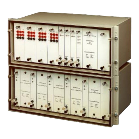
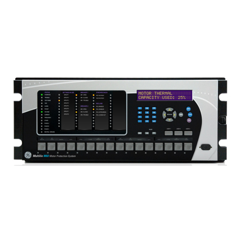
GE 239 User manual

239
MOTOR PROTECTION RELAY
Instruction Manual
Firmware Revision: 2.6x
239PC Software: 2.6x or newer
Manual P/N: 1601-0060-D9
Copyright © 2002 GE Multilin
GE Multilin
215 Anderson Avenue, Markham, Ontario
Canada L6E 1B3
Tel: (905) 294-6222 Fax: (905) 201-2098
Internet: http://www.GEindustrial.com/multilin Manufactured under an
ISO9002 Registered system.
g
GE Power Management
TRIP
ALARM
AUXILIARY
SERVICE
PICKUP
COMMUNICATE
RESET
STORE
ACTUAL
VALUE
MESSAGE
SETPOINT
239 Motor Protection Relay
CAUSE OF LAST TRIP:
MECHANICAL JAM
C US


These instructions do not purport to cover all details or variations in equipment
nor provide for every possible contingency to be met in connection with instal-
lation, operation, or maintenance. Should further information be desired or
should particular problems arise which are not covered sufficiently for the pur-
chaser’s purpose, the matter should be referred to the General Electric
Company.
To the extent required the products described herein meet applicable ANSI,
IEEE, and NEMA standards; but no such assurance is given with respect to
local codes and ordinances because they vary greatly.


GE Multilin 239 Motor Protection Relay i
TABLE OF CONTENTS
1. OVERVIEW 1.1 239 RELAY FEATURES....................................................1-1
1.2 TYPICAL APPLICATIONS.................................................1-5
1.3 ORDER CODE ..................................................................1-6
1.4 SPECIFICATIONS.............................................................1-7
2. INSTALLATION 2.1 MOUNTING .......................................................................2-1
2.2 PRODUCT IDENTIFICATION ...........................................2-2
2.3 EXTERNAL CONNECTIONS ............................................ 2-3
2.4 DIELECTRIC STRENGTH TESTING..............................2-13
3. OPERATION 3.1 FRONT PANEL..................................................................3-1
3.2 DISPLAY............................................................................3-2
3.3 STATUS INDICATORS .....................................................3-2
3.4 KEYS .................................................................................3-3
3.5 SETPOINT ACCESS.........................................................3-6
3.6 DEFAULT MESSAGES .....................................................3-6
4. PROGRAMMING 4.1 SETPOINT ENTRY METHODS.........................................4-1
4.2 S1: 239 SETUP .................................................................4-3
4.3 S2: SYSTEM SETUP.........................................................4-9
4.4 S3: OUTPUT RELAYS ....................................................4-13
4.5 S4: PROTECTION...........................................................4-15
4.6 TEMPERATURE..............................................................4-29
4.7 SWITCH INPUTS ............................................................4-33
4.8 MULTI-SPEED MOTOR .................................................. 4-33
4.9 S5: TESTING...................................................................4-36
5. MONITORING 5.1 ACTUAL VALUES VIEWING.............................................5-1
5.2 A1: STATUS ...................................................................... 5-2
5.3 A2: METERING .................................................................5-6
5.4 A3: PRODUCT INFO.........................................................5-9
6. 239PC SOFTWARE 6.1 OVERVIEW .......................................................................6-1
6.2 HARDWARE CONFIGURATION.......................................6-1
6.3 239PC VERSION...............................................................6-2
6.4 INSTALLING/UPGRADING 239PC...................................6-3
6.5 239PC MENU STRUCTURE.............................................6-6
6.6 CONFIGURING 239PC .....................................................6-7

ii 239 Motor Protection Relay GE Multilin
TABLE OF CONTENTS
6.7 239 FIRMWARE UPGRADE..............................................6-9
6.8 USING 239PC..................................................................6-12
7. COMMUNICATIONS 7.1 MODBUS PROTOCOL ......................................................7-1
7.2 ELECTRICAL INTERFACE................................................7-1
7.3 DATA FRAME FORMAT / DATA RATE.............................7-1
7.4 DATA PACKET FORMAT..................................................7-2
7.5 ERROR CHECKING ..........................................................7-2
7.6 TIMING...............................................................................7-4
7.7 239 SUPPORTED MODBUS FUNCTIONS.......................7-4
7.8 03/04: READ SETPOINTS / ACTUAL VALUES.................7-4
7.9 05: EXECUTE OPERATION..............................................7-5
7.10 06: STORE SINGLE SETPOINT........................................7-6
7.11 07: READ DEVICE STATUS..............................................7-7
7.12 08: LOOPBACK TEST .......................................................7-8
7.13 16: STORE MULTIPLE SETPOINTS.................................7-9
7.14 16: PERFORMING COMMANDS.....................................7-10
7.15 ERROR RESPONSES.....................................................7-11
7.16 MEMORY MAP INFORMATION ......................................7-11
7.17 USER DEFINABLE MEMORY MAP ................................7-11
7.18 239 MEMORY MAP .........................................................7-13
7.19 MEMORY MAP DATA FORMATS...................................7-31
8. TESTING 8.1 PRIMARY INJECTION TESTING ......................................8-1
8.2 SECONDARY INJECTION TESTING................................8-1
8.3 PHASE CURRENT ACCURACY .......................................8-2
8.4 PHASE CURRENT OVERLOAD........................................8-3
8.5 PHASE UNBALANCE ALARM...........................................8-3
8.6 GROUND CURRENT ACCURACY....................................8-5
8.7 GROUND ALARM AND TRIP............................................8-5
8.8 SWITCH INPUT .................................................................8-6
8.9 ANALOG OUTPUT.............................................................8-6
8.10 THERMISTOR ALARM ......................................................8-7
8.11 RTD MEASUREMENT.......................................................8-7
8.12 POWER FAILURE / NON-VOLATILE MEMORY...............8-7
8.13 ROUTINE MAINTENANCE VERIFICATION......................8-8

GE Multilin 239 Motor Protection Relay 1-1
1 OVERVIEW 1 OVERVIEW
1
239 INSTRUCTION MANUAL 1 OVERVIEW 1.1 239 RELAY FEATURES
The GE Multilin 239 relay is designed to fully protect three phase AC motors against conditions
which can cause damage. In addition to motor protection, the relay has features that can protect
associated mechanical equipment, give an alarm before damage results from a process malfunction,
diagnose problems after a fault and allow verification of correct relay operation during routine main-
tenance. Using the ModBus serial communications interface, motor starters throughout a plant can
be connected to a central control/monitoring system for continuous monitoring and fast fault diagno-
sis of a complete process.
One relay is required per motor. Since phase current is monitored through current transformers,
motors of any line voltage can be protected. The relay is used as a pilot device to cause a contactor
or breaker to open under fault conditions; that is, it does not carry the primary motor current. When
the over temperature option is ordered, up to 3 RTDs can be monitored. These can all be in the sta-
tor or 1 in the stator and 2 in the bearings. Installing a 239 in a motor starter for protection and moni-
toring of motors will minimize downtime due to process problems.
PROTECTION
• Overload (15 selectable curves)
• Short circuit
• Locked rotor
• Stall / mechanical jam
• Repeated starts (Mod 505)
• Single phase / unbalance
• Ground fault
• Overtemperature (Thermistor & 3 RTDs)
• Undercurrent
• Overload warning
• Breaker failure
FEATURES
• Status/current/temperature display
• Fault diagnosis
• Trip record
• Memory lockout
• Thermal capacity / load% / RTD analog
output
• Trip / alarm / auxiliary / service relay out-
puts
• Motor Running Hours
• Motor maximum current on last start
• Simulation mode for field testing
• Clear LCD display
• RS485 Modbus communications interface
• AC/DC control power
• Compact size, fits most starters
• Update options and/or MODs in field
• CSA/UL Approved

1-2 239 Motor Protection Relay GE Multilin
1 OVERVIEW 1 OVERVIEW
1
Figure 1–1: CONTINUOUS PROTECTION FEATURES
819763AF.CDR
51
49
38
50
37
86
74
46
50G
48
MOTOR
LOAD
AUXILIARY
RELAY
SERVICE
RELAY
RS485
ALARM
RELAY
TRIP
RELAY
LOCKED ROTOR
SHORT CIRCUIT
TIMED OVERLOAD
INSTANTANEOUS
GROUND FAULT
STATOR OVER
TEMPERATURE
BEARING OVER
TEMPERATURE
UNBALANCE
UNDERCURRENT
SERVICE
ALARM
FAULT/
ALARM/
PROCESS
CONTROL
FAULT/
PROCESS
ALARM
52
3 PHASE
4160V BUS
400A
FUSED
CONTACTOR
3
PHASE
CTs
TRIP
GROUND
CT
THERMISTOR/
STATOR RTD
BEARING
RTDs
RS485 REMOTE
COMMUNICATION
239 RELAY

GE Multilin 239 Motor Protection Relay 1-3
1 OVERVIEW 1 OVERVIEW
1
Figure 1–2: FEATURE HIGHLIGHTS – FRONT
TRIP
ALARM
AUXILIARY
SERVICE
PICKUP
COMMUNICATE
RESET
STORE
ACTUAL
VALUE
MESSAGE
SETPOINT
DISPLAY
40 character illuminated display for all light conditions.
• Setpoints
• Actual values
• Status messages
• Fault conditions
STATUS INDICATORS
• Trip: Lit when the 239 detects a trip.
• Alarm: Lit when the 239 detects an alarm.
• Auxiliary: Lit when the auxiliary relay is operated.
• Service: Lit when the 239 detects an internal
fault condition.
• Pickup: Lit when motor full load or ground
is exceeded.
• Communicate: Off if there is no communication at all,
flashes if RS485 activity but invalid
messages, and on (steady) if
communication is successful.
pickup
KEYPAD
Rubber keypad makes installed unit dust tight and splash
proof. Meets IP53/NEMA12.
PROTECTIVE DOOR
Covers keys when not in use.
COMPACT DESIGN
Replaces many discrete components
with one standard unit.
239 Motor Protection Relay
CAUSE OF LAST TRIP:
MECHANICAL JAM
819790A -X2.CDR

1-4 239 Motor Protection Relay GE Multilin
1 OVERVIEW 1 OVERVIEW
1
Figure 1–3: FEATURE HIGHLIGHTS – REAR
819790AH-X3.CDR
COMMUNICATIONS
RS485 serial communications, 1200-19200 baud for
remote monitoring, setpoint programming, and
commands. Modbus RTU protocol.
®
SWITCH INPUTS
Enable/disable setpoint programming.
ACCESS:
Over-rides lockout for process restarting.
RESTART:
Field reset after a trip.
RESET:
User specified inputs.
OPTION 1&2:
OPTIONAL ANALOG OUTPUT
Select output as: thermal capacity used, current asa%of
full load, average current, RTD 1-3 temperature. Isolated
4-20 mA for PLC process input or 0-1 mA for thermal
capacity meter.
CUSTOMER ACCESSIBLE FUSE
Door slides open for easy access
to fuse.
AC/DC CONTROL POWER
Universal control power
90-300 VDC/70-265 VAC.
GROUND CT INPUT
5A or 50:0.025 CT input for
residually connected phase CTs
or separate core balance CT.
PHASE CT INPUTS:
3 isolated phase CT inputs.
Accept 1 amp or 5 amp secondary.
TEMPERATURE SENSING
NTC or PTC thermistor input.
OPTIONAL 3 RTD INPUTS
Mix RTD types. Separate stator and bearing monitoring
OPTIONAL DIRECTIONAL GROUND SENSING
Polarizing voltage input for directional ground sensing
(MOD 509)
4 RELAYS
Cause motor to trip by opening contactor
or energizing breaker trip coil.
TRIP:
Signals an alarm is present.
ALARM:
Programmable for control or separate trip/alarm.
Serial port commands for remote control.
AUXILIARY:
Signals internal relay fault.
Service is required.
SERVICE:

GE Multilin 239 Motor Protection Relay 1-5
1 OVERVIEW 1 OVERVIEW
1
1.2 TYPICAL APPLICATIONS
Versatile features and simple programming controls make the 239 an ideal choice for motor and
equipment protection in a wide range of applications. In addition to basic electrical protection for
motors, the 239 can protect against common faults due to process problems, such as:
1. Mechanical protection of pumps using the undercurrent feature to detect loss of suction or a
closed discharge valve.
2. Personnel safety and mechanical protection of fans against loss of air flow in mines or flow in
steam generating boilers using the undercurrent feature.
3. Electrical protection of compressor motors from excessive run up time caused by an open outlet
using the start timer.
4. Mechanical protection of gears, pumps, fans, saw mill cutters, and compressors against mechan-
ical jam using the mechanical jam trip feature.
5. Safety to personnel from shock hazard using the ground fault feature to detect winding shorts or
leakage currents from moisture in mines.
6. Protection of motors and equipment from operator abuse using the thermal memory lockout
Cost savings are provided using versatile features such as:
1. Diagnostic information after a trip to identify problems and bring the process back on line quickly.
2. Fault indication of ground fault without shutdown to warn that corrective maintenance is required.
3. Simplified spare parts stocking and initial specification design using one universal model for
many motor sizes, applications and settings.
4. Serial communication using the popular Modbus protocol to remotely monitor all values, program
setpoints, issue commands and diagnose faults to minimize process disruptions.
5. Output of motor current suitable for programmable controller interface (4 to 20 mA).

1-6 239 Motor Protection Relay GE Multilin
1 OVERVIEW 1 OVERVIEW
11.3 ORDER CODE
a) MODIFICATIONS
• MOD 500: Portable test/carrying case
• MOD 501: 20 to 60 V DC / 20 to 48 V AC control power
• MOD 504: Removable terminal blocks
• MOD 505: Enhanced start protection
• MOD 506: Custom programmable overload curve
• MOD 509: Directional ground sensing with 120 V AC polarizing voltage
• MOD 512: 1 AMP Ground CT input
• MOD 513: Class 1 Division 2 operation
• MOD 517: Australian Mines approval
b) ACCESSORIES
• 239PC Windows software (free upon request)
• Phase and ground CTs
• RS232 to RS485 converter (required to connect a computer to the 239 relay(s) to run 239PC
• RS485 Terminating Network
• 2.25” collar for limited depth mounting (1009-0068)
• Large size (8.5 x 11”) instruction manual (free upon request)
c) CONTROL POWER
• 90 to 300 V DC / 70 to 265 V AC standard
• 20 to 60 V DC / 20 to 48 V AC (MOD 501)

GE Multilin 239 Motor Protection Relay 1-7
1 OVERVIEW 1 OVERVIEW
1
1.4 SPECIFICATIONS
PHASE CURRENT INPUTS
CONVERSION: true rms, 16 samples/cycle
CT INPUT: 1 A and 5 A secondary
RANGE: 0.1 to 11 ×phase CT primary
FREQUENCY: 20 to 300 Hz
ACCURACY: ±2% of full scale
GROUND CURRENT INPUTS
CONVERSION: true rms, 16 samples/cycle
CT INPUT: 5 A secondary and 50:0.025
RANGE: 0.03 to 1.4 ×CT primary (5A CT)
0.05 to 16.0 A (50:0.025 CT)
FREQUENCY: 20 to 300 Hz
ACCURACY:
5 A CT: ±2% of full scale (5A CT)
50:0.025 CT: ±0.03 A (0 to 0.49 A)
±0.07 A (0.50 to 3.99 A)
±0.20 A (4.00 to 16.00 A)
OVERLOAD CURVES TRIP TIME
CURVES: 15 curves, fixed shape
OVERLOAD PICKUP INHIBIT: 1.00 to 5.00 ×FLC
PICKUP LEVEL: 1 to 1500 A
ACCURACY:
PICKUP: ± 1% of Displayed Value
TIME: ± 2% of trip time or ± 1 sec
whichever is greater
SHORT CIRCUIT & GROUND TRIP
GROUND TRIP LEVEL: 0.05 to 15A (50:0.025 CT)
3 to 100% (5 A CT)
S/C TRIP LEVEL: 1 to 11 × CT PRI / OFF
INTENTIONAL DELAY:INST. or 10 to 60000 ms
programmable
INST: 20 to 45 ms
* TOTAL DELAY: INST + INTENTIONAL
* trip time accuracy guaranteed if
current > 1.4 ×trip level setting
BREAKER FAILURE TIMING
DELAY: INST. or 10 to 60000 ms
programmable
INST: 20 to 45ms
* TOTAL DELAY: INST + INTENTIONAL
* trip time accuracy guaranteed if
current > 1.4 ×trip level setting
START PROTECTION
THERMAL: separate start & run protection
ACTIVATION: inrush 3 phase current increases
from <5% to >101% FLC in 1 s
DEACTIVATION: current drops to <100% FLC
motor running if current >5%
FLC
LOCKED ROTOR: 0.5 to 11.0 ×FLC
SAFE STALL TIME:1.0 to 600.0 sec
THERMAL MODELING
THERMAL CAPACITY: separate start/run,
exponential cool down
COOL RATE:
STOP: 1 to 5000 minutes programmable
RUN: 50% of stopped cool time
HOT/COLD: 50 to 100%, hot after 15 min running
LOCKOUT: 1 to 5000 min programmable ±20%
power on / off
UNBALANCE
RANGE: 5 to 100% / OFF
ACCURACY: ± 2%
DELAY: 0 - 60 sec
CALCULATION:
where:
I
AV
= average phase current
I
M
= current in phase with max dev. from
I
AV
I
FLC
= full load current setting
THERMISTOR
TYPE: PTC or NTC programmable
HOT RESISTANCE:100 to 30 000 Ω
COLD RESISTANCE: 100 to 30 000 Ω
DELAY: 2 sec
ACCURACY: ±5% or 100 Ω, whichever is
greatest
UNDERCURRENT
RANGE: 5 to 100% FLC / OFF
DELAY: 0 to 250 sec
If
I
AV
I
FLC
, UB%≥
I
M
I
AV
–
I
AV
----------------------- 100×=
If
I
AV
I
FLC
, UB%<
I
M
I
AV
–
I
FLC
----------------------- 100×=

1-8 239 Motor Protection Relay GE Multilin
1 OVERVIEW 1 OVERVIEW
1RTDs (OPTIONAL)
INPUTS: 3 RTDs, stator/bearing prog.
TYPE: 100 Pt (DIN 43760), 100 Ni, 120
Ni, 10 Cu programmable
RANGE: –40 to 200 °C/ –40 to 400 °F
TRIP/ALM RANGE: 0 to 200 °C / 0 to 400 °F
DEAD BAND: 2 °C / 4 °F
ACCURACY: ±2 °C / ±4 °F
LEAD RESISTANCE:
Pt or Ni RTD: 25 Ω max
Cu RTD: 3 Ω max
3 wire lead resistance compensation
COMMUNICATIONS
TYPE: RS485 2 wire, half duplex, isolated
BAUD RATE: 1200 to 19.2k bps
PROTOCOL: Modbus®RTU
FUNCTIONS: Read/write setpoints, read actual
values, execute commands
ANALOG OUTPUT (OPTIONAL)
ACCURACY: ±2% of full scale reading
ISOLATION: 36 V DC isolated, active source
OUTPUT RELAYS
CONFIGURATION: FORM C NO/NC
CONTACT MATERIAL: SILVER ALLOY
CT INPUTS
50:0.025 GROUND INPUT WITHSTAND:
CONTINUOUS: 150 mA
MAXIMUM: 12 A for 3 cycles
50:0.025 input can be driven by a 50:0.025 CT.
SWITCH INPUTS
TYPE: dry contacts
OUTPUT: 29 V DC, 10 mA (pulsed)
DURATION: 100 ms minimum
CONTROL POWER
INPUT: 90 to 300 VDC or
70 to 265 VAC, 50/60 Hz
POWER: 10 VA (nominal) 20 VA (max)
HOLDUP: non-failsafe trip: 200 ms
failsafe trip: 100 ms
both times at 120VAC / 125VDC
It is recommended that all 239 relays be
powered up at least once per year to avoid
deterioration of electrolytic capacitors in
the power supply.
PROGRAMMABLE
OUTPUT 0-1 mA 0-20 mA 4-20 mA
MAX LOAD 2400 Ω600 Ω600 Ω
MAX OUTPUT 1.1 mA 21 mA 21 mA
92/7$*( 0$.(&$55<
&217,18286 0$.(
&$55<
V
%5($.
RESISTIVE 30 VDC 10 30 10
125 VDC 10 30 0.5
250 VDC 10 30 0.3
INDUCTIVE
(L/R=7 ms) 30 VDC 10 30 5
125 VDC 10 30 0.25
250 VDC 10 30 0.15
RESISTIVE 120 VAC 10 30 10
250 VAC 10 30 10
INDUCTIVE
PF=0.4 120 VAC 10 30 10
250 VAC 10 30 10
CT INPUT
(A) BURDEN
VA Ω
PHASE CT
(1A)
1 0.009 0.01
5 0.2 0.01
20 3.5 0.01
PHASE CT
(5A)
5 0.04 0.002
25 0.9 0.002
100 16 0.002
GROUND
CT (5A)
5 0.04 0.002
25 1.1 0.002
100 17 0.002
GROUND
CT
(50:0.025)
0.025 0.07 116
0.1 1.19 119
0.5 30.5 122
BURDEN
1s xCT 5s xCT continuous
xCT
PHASE CT
(1A) 100 40 3
PHASE CT
(5A) 100 40 3
GROUND
CT (5A) 100 40 3
NOTE

GE Multilin 239 Motor Protection Relay 1-9
1 OVERVIEW 1 OVERVIEW
1
FUSE TYPE/RATING
5 ×20mm, 2.5 A, 250V
Slow blow, High breaking capacity
ENVIRONMENT/GENERAL INFO
POLLUTION DEGREE: 2
OVERVOLTAGE CATEGORY: 2
INSULATION VOLTAGE: 300 V
OPERATING TEMPERATURE RANGE: 0°C to 60°C
STORAGE TEMPERATURE RANGE: –40°C to 70°C
IP CLASS: 40
INSTALLATION
WARNING: HAZARD may result if the
product is not used for its
intended purpose.
VENTILATION REQUIREMENTS: None
CLEANING REQUIREMENTS: None
TYPE TESTS
DIELECTRIC STRENGTH: 2.0 kV for 1 minute to
relays, CTs, power supply
INSULATION RESISTANCE:IEC255-5, 500 V DC
TRANSIENTS: ANSI C37.90.1 Oscillatory 2.5
kV / 1 MHz; ANSI C37.90.1 Fast
Rise 5 kV / 10 ns; Ontario Hydro
A-28M-82; IEC255-4 Impulse/
High Frequency Disturbance
Class III Level
IMPULSE TEST: IEC 255-5 0.5 Joule 5 kV
RFI: 50 MHz/15 W Transmitter
EMI: C37.90.2 Electromagnetic Inter-
ference @ 150 MHz and 450
MHz, 10 V/m
STATIC: IEC 801-2 Static Discharge
HUMIDITY: 95% non-condensing
TEMPERATURE: –10°C to +60°C ambient
ENVIRONMENT: IEC 68-2-38 Temp/Humidity
Cycle
DUST/MOISTURE: NEMA 12/IP53
PACKAGING
SHIPPING BOX: 8½" × 6" × 6" (L × H × D)
215 mm × 152 mm × 152 mm
(L × H × D)
SHIP WEIGHT: 5 lbs. / 2.3 kg
CERTIFICATION/COMPLIANCE
ISO: Manufactured under an
ISO9001 recognized program
UL: Recognized under E83849
CSA: Approved under LR41286
NOTE: Specifications subject to change without notice.

1-10 239 Motor Protection Relay GE Multilin
1 OVERVIEW 1 OVERVIEW
1

GE Multilin 239 Motor Protection Relay 2-1
2 INSTALLATION 2 INSTALLATION
2
239 INSTRUCTION MANUAL 2 INSTALLATION 2.1 MOUNTING
Physical dimensions for the 239 and the required cutout dimensions are shown below. Once the cut-
out and mounting holes are made in the panel, use the eight #6 self tapping screws supplied to
secure the relay. Mount the relay on a panel or switchgear door to allow operator access to the front
panel keys and indicators.
Figure 2–1: PHYSICAL DIMENSIONS

2-2 239 Motor Protection Relay GE Multilin
2 INSTALLATION 2 INSTALLATION
2
2.2 PRODUCT IDENTIFICATION
Product attributes will vary according to the configuration and options installed based on the cus-
tomer order. Before applying power to the relay, examine the label on the back of the 239 and check
that the correct options are installed.
The information included on the product label is explained below:
Figure 2–2: 239 PRODUCT LABEL (EXAMPLE)
1. MODEL NO: The model number shows the configuration of the relay. The model number for a
basic unit is 239. RTD and AN will appear in the model number only if the RTD option or Analog
Output option is installed.
2. SUPPLY VOLTAGE: Indicates the 239 power supply input configuration. The 239 shown above
can accept any AC 50/60Hz voltage from 70 to 265 V AC or DC voltage from 90 to 300 V DC.
3. TAG#: This is an optional identification number specified by the customer.
4. MOD#s: These are used if unique features have been installed for special customer orders.
These numbers should be available when contacting GE Multilin for technical support. Up to five
MOD#s can be installed into the 239.
5. SERIAL NO: Indicates the serial number for the 239 in numeric and barcode format.
The following table shows the revision history of the 239. Each revision of the instruction manual cor-
responds to a particular firmware revision in the 239. The instruction manual revision is located on
the first page of the manual as part of the manual P/N (1601-00XX-Revision). The 239 firmware revi-
sion is loaded in the relay and can be found by scrolling to the display message $ 352'8&7
,1)2?),50:$5(9(56,216?0$,1352*5$09(5.
When using the manual to determine relay features and settings, ensure that the revision corre-
sponds to the 239 firmware revision using the table below. For a large instruction manual (8.5” ×11”)
the part number is 1601-0067; for a small instruction manual (5.5” ×7.25”) it is 1601-0060.
Table 2–1: FIRMWARE/MANUAL REVISIONS TABLE
MANUAL PART NO. FIRMWARE VERSION MANUAL PART NO. FIRMWARE VERSION
1601-00XX-C4 2.00 1601-00XX-D3 2.3x
1601-00XX-C5 2.01 1601-00XX-D4 2.3x
1601-00XX-C6 2.10 1601-00XX-D5 2.40
1601-00XX-C7 2.11 1601-00XX-D6 2.50
1601-00XX-C8 2.12 1601-00XX-D7 2.51
1601-00XX-D1 2.20 1601-00XX-D8 2.51
1601-00XX-D2 2.30 1601-00XX-D9 2.6x
110.000
SUPPLY VOLTAGE
TAG# MOD#
®
NRTL
MAXIMUM CONTACT RATING
250 VAC 10A RESISTIVE
1/4 HP 125VAC 1/2HP 250VAC
12
11
10
9
8
7
654
3
2
1
MAXIMUM CONTACT RATING
250 VAC 10A RESISTIVE
1/4HP 125VAC 1/2HP 250VAC
MODEL
SUPPLY VOLTAGE SERIAL NO.:
TAG# 1234-567-89
90-300VDC 20VA
70-265VAC 50/60HZ 20VA
D6401234
239-RTD-AN
MADE IN CANADA
MOD#s NONE
FIRMWARE
64D240C4.000
GE Power Management
819790AH-X4.CDR

GE Multilin 239 Motor Protection Relay 2-3
2 INSTALLATION 2 INSTALLATION
2
2.3 EXTERNAL CONNECTIONS
Signal wiring is to box terminals that can accommodate wire as large as 12 gauge. CT connections
are made using #8 screw ring terminals that can accept wire as large as 8 gauge (see Figure 2–3:
TYPICAL WIRING DIAGRAM on page 2–4). A minimal configuration will include connections for
control power, phase CTs and the trip relay. Other features can be wired as required. Considerations
for wiring each feature are given in the sections that follow.
Table 2–2: EXTERNAL CONNECTIONS
CT ROW SIGNAL LOWER ROW SIGNAL UPPER ROW
1 Phase A CT 5A 13 Safety ground 36 Control live (+)
2 Phase A CT 1A 14 Filter ground 37 Control neutral (–)
3 Phase A CT COM 15 RS485 A+ 38 Sw com
4 Phase B CT 5A 16 RS485 B– 39 Sw com
5 Phase B CT 1A 17 RS485 ground 40 Sw com
6 Phase B CT COM 18 Analog out + 41 Sw com
7 Phase C CT 5A 19 Analog out – 42 Sw com
8 Phase C CT 1A 20 Analog out shield 43 Access sw +
9 Phase C CT COM 21 Thermistor in + 44 Restart sw +
10 Ground CT 5A 22 Thermistor com 45 Reset sw +
11 Ground CT 50:0.025 23 Trip NO 46 Option 1 sw +
12 Ground CT COM 24 Trip COM 47 Option 2 sw +
25 Trip NC 48 RTD shield
26 Alarm NO 49 RTD1 hot
27 Alarm COM 50 RTD1 comp
28 Alarm NC 51 RTD1 ret
29 Auxiliary NO 52 RTD2 hot
30 Auxiliary COM 53 RTD2 comp
31 Auxiliary NC 54 RTD2 ret
32 Service NO 55 RTD3 hot
33 Service COM 56 RTD3 comp
34 Service NC 57 RTD3 ret
35 Unused 58 Unused

2-4 239 Motor Protection Relay GE Multilin
2 INSTALLATION 2 INSTALLATION
2
Figure 2–3: TYPICAL WIRING DIAGRAM
2 CT CONNECTION
(NO GROUND)
RESIDUAL GROUND CONNECTION
ZERO SEQUENCE GROUND CONNECTION
PHASE A CT PHASE A CT
PHASE A CT
STARTER
80-300 VDC
70-265 VAC 50/60 Hz
CONTROL POWER
SUPPLY 50:0.025
GROUND CT
CONTACTOR
COIL
SWITCHGEAR
GROUND BUS
PHASE C CT PHASE C CT
PHASE C CT
PHASE B CT
PHASE B CT
L1 L1
L1L1
A
B
C
TWIST
LEADS
L2 L2
L2L2 MOTOR
L3 L3
L3L3
11
1
22
2
33
3
44
4
55
5
66
6
77
7
88
8
99
9
10 10
10
11 11
11
12 12
12
5A 5A
5A
5A 5A
5A
5A 5A
5A
5A 5A
5A
1A 1A
1A
1A 1A
1A
1A 1A
1A
COM COM
COM
COM COM
COM
COM COM
COM
COM COM
COM
PHASE A PHASE A
PHASE A
PHASE B PHASE B
PHASE B
PHASE C PHASE C
PHASE C
GROUND GROUND
GROUND
50:0.025 50:0.025
50:0.025
CONTROL
POWER
NL
START STOP
GENERAL ALARM
CONTROL
POWER
23
24
25
NO
NO
NO
NO
IN
IN
IN
IN
IN
COM
COM
COM
COM
COM
COM
COM
COM
COM
NC
NC
NC
NC
26
27
28
29
30
31
32
33
34
43
38
44
39
45
40
46
41
47
42
SETPOINT
ACCESS
ACCESS
KEY SWITCH
EMERGENCY
RESTART
EMERGENCY
RESTART
EXTERNAL
RESET
EXTERNAL
RESET
OPTION 1
OPTION 1
OPTION 2
OPTION 2
S1
S2
S3
S4
S5
SWITCH INPUTS
OUTPUT RELAYS
RELAY #1
TRIP
RELAY #2
ALARM
RELAY #3
AUXILIARY
RELAY #4
SERVICE
CURRENT INPUTS
239 MOTOR PROTECTION RELAY
13 14 36 37
SAFETY
GROUND
FILTER
GROUND
L+N-
RS485 +
RS485 -
485 GROUND
SERIAL
RTD#1
RTD#2
RTD#3
RTD TEMPERATURE SENSING ANALOG
OUT
0-1mA
4-20mA
15
16
17
18
19
20
SHIELD
USE SHIELDED TWISTED
PAIR WIRE
RS485
THERMAL
CAPACITY
THERMISTOR
IN+
COM
21
22
48
49
50
51
52
SHIELD
HOT
COMP
RET
HOT
53
54
55
56
57
COMP
RET
HOT
COMP
RET
STATOR
THERMISTOR
STATOR
RTD
STATOR/
BEARING RTD
STATOR/
BEARING RTD
USE SHIELDED WIRE
819829B6.CDR
819751B5.DWG
NOTES:
1) 3)
4)
2)
RELAY CONTACT STATE SHOWN WITH
CONTROL POWER NOT APPLIED.
SHIELD TERMINALS ARE INTERNALLY
CONNECTED TO SAFETY GROUND
TERMINAL 13
RTD TEMPERATURE SENSING
AND ANALOG OUTPUT OPTIONAL
RELAY FACTORY DEFAULTS:
TRIP, ALARM, AUXILIARY:
SERVICE:
NON-FAILSAFE
FAILSAFE
CC
GE Power Management
Other manuals for 239
1
Table of contents
Other GE Protection Device manuals