Polivac PV25 User manual

POLIVAC PV25 SUCTION
POLISHER
Operations Manual & Trouble Shooting Guide

Version 6/2000
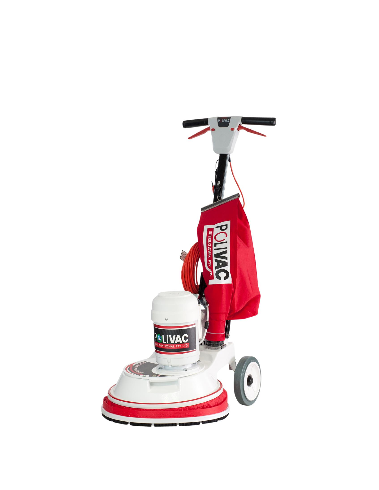
Operating instructions of a PV25-C25-C27
Please find the following correct operating procedure for the operation of the Polivac
range of polishers and scrubbers, PV25, C25 and C27.
1. Plug in power cable. Power supply will be visible via the red light on the top of the
handle.
2. Tilt the machine back by using the handle.
3. a) Place the Brush or Pad Holder over the 3 Leaf clover connection and turn it clock-
wise to lock the Brush/Pad Holder into position.
b) If the connection has a brass 3 puck clutch fitted, locate the Brush/Pad Holder on the
metal drive clutch, by slotting grooves together, then turn Brush/Pad Holder sharply to
the left.
4. Once the Brush/Pad Holder is fitted, stand the machine back up.
5. Slightly lift the handle up and manoeuvre the wheels backwards and up out of the way
(the wheels must be off the floor when polishing).
6. The handle height must be adjusted to suit individual operators body proportions. Adjust
the ergonomic handle to the correct height by placing your foot or hand on the ratchet
lever, then positioning the handle. The correct height of the handle is around the groin
region.
7. When the handle is set at the correct height, the arms should grip the handle in a
comfortable, but loose manner (if your arms are bent at the elbows this is an indication
that you are applying too much effort to control the machine) Re-adjust the handle.
8. To start the machine, first you must depress the red safety button that is next to the hand
trigger, then grasp either of the red triggers, and the motor will engage the brush. Do not
force the trigger without first releasing the safety button as this will damage the safety
release in the trigger mechanism. Once the machine is on, the safety button can be
released.
9. To facilitate the correct swinging motion of the machine, lift the handle slightly forward to
get the polisher to move to the right and lower the handle to get the machine to move to
the left. This requires minimal effort. So, if you are fighting the machine for control you
have the handle set at the wrong height or your pad or cloverleaf locking mechanism is
damaged.
10. (PV25 Only) To use the vacuum system whilst polishing, switch the vac motor to the on
position. The vacuum will be activated upon starting the machine.
11. When stripping floors using the PV25, ensure vacuum motor is switched OFF.
12. Ensure that brushware is removed from the machine after use and before storing
machine away.
How to Operate a
Polishing/Scrubbing Machine
PV25
, C25 AND C27

Suction Polisher - PV25 SV25 SV30
Drawings by: LeanSynergicDesign.com.au
Drive & Base Assembly
40
44
42
41
31
32
33
29
28
36
27
37
24
25
35
26
30
21
20
15
14
39
38
46
22
23
34
16
18
3
8
10 12
48
47
49
50
13
51
52
19
45
5
4
6
2
11
9
43
1
56
55
54
7
17
57
58
59
53

Suction Polisher - PV25 SV25 SV30
Drawings by: LeanSynergicDesign.com.au
Drive & Base Assembly - Part List
No Code Description
1 VPV216 Skirt-Painted
2 VPV190 Fan Housing
3 AAA584 Set Screw 1/4'' x 1'' Zinc
4 AAG236 Washer 1/4'' x 5/8'' Zinc Bright
5 AAF140 Nut Nyloc 1/4'' UNC
6 VPV008 Gaiter
7 VPA138 Lever-Rachet
8 AAD061 Bolt 5/16'' x 1.1/2'' Zinc
9 AAG385 Washer 5/16'' x 7/8'' 16G Z/P
10 VPA782 Spacer
11 VPA139 Torsion Spring
12 SLB043 Nut Nyloc 5/16'' UNC
13 VPV218 Retaining Pin-Axle
14 VPV094 Clamp-Hose Dust Bag
15 VPV058 Hose-Dust Bag
16 VPV090 Skirt Assy (PV25/PV25TS) for SV25/SV30 VPV090 BLK
17 VPV250 Vac Motor Complete
18 SLB035 Rivet ASL 5-6
19 VPV063 Dust Bag
20 VPV051 Closure-Dust Bag
21 VPV156 Bag Ring
22 VPA950 Handle Retaining Pin
23 VPA954 Clip
24 VPA116 Gear Shaft
25 VPA412
VPA374 Quick Release Adaptor [PV25]
Brush Coupling [SV25,SV30] - Not Pictured

Suction Polisher - PV25 SV25 SV30
Drawings by: LeanSynergicDesign.com.au
No Code Description
26 VPA114 Bearing-Bottom
27 VPA113 Gear Cover
28 VPA118 Seal-Bottom
29 VPA411 Drive Gear
30 VFB115 Key
31 VPA495 Base Luggless
32 VPA121 Washer Wavy
33 VPA570 Bearing-Top
34 PC40B1 Brush Assembly
35 AAA628
AAA635 Cap Screw 5/16'' x 1'' Socket HD [PV25]
Cap Screw 5/16'' x 3/4'' Socket HD [SV25,SV30]
36 VPA122 Washer TAB 1/2'' OD x 1/4'' ID
37 AAA564 Bolt 1/4'' NC x 3/4'' Zinc High Intensity
38 AAG236 Washer 1/4'' x 5/8'' Zinc Bright
39 AAD041 Bolt 1/4'' x 1.1/4'' Zinc
40 VPA975CMG
VPA011CMG
VPA013CMG
Motor [PV25]{VPV525CMG - Motoring gearbox}
Motor [SV25]{VPV522CMG - Motoring gearbox}
Motor [SV30]{VPV574CMG - Motoring gearbox}
41 AAG236 Washer 1/4'' x 5/8'' Zinc Bright
42 AAA564 Bolt 1/4'' NC x 3/4'' Zinc High Intensity
43 VPA104 Oil Seal Top
44 LAB001
LAB002 Motor Label [PV25, SV25]
Motor Label [SV30]
45 AAG237 Washer 1/4'' x 3/4'' Zinc Bright 14x34 BSWZ
46 AAF140 Nut Nyloc 1/4'' UNC
47 VPV170 Axle
48 VPV166 Wheel-Rubber Tyre
49 AAG470 Washer 1/2'' x 1'' Zinc Bright
Drive & Base Assembly - Part List

Suction Polisher - PV25 SV25 SV30
Drawings by: LeanSynergicDesign.com.au
Drive & Base Assembly - Part List
No Code Description
50 VPA355 Roll Pin 3/32'' x 7/8'' ZP
51 GCA292 Rachet Cap 12mm
52 VWA634 Bush Nylon
53 LAB005
LAB004
LAB010
Label [PV25]
Label [SV25]
Label [SV30]
54 VPV459 Cable Tie
55 VPV106 Gasket 5mm x 9mm
56 VPV251 Gasket 10mm x 9mm
57 VPV087 Buffer-Skirt
58 VPV239 Insert-Buffer
59 VPA001 Weight [SV25, SV30]

Suction Polisher - PV 25 SV25 SV30
Drawings by: LeanSynergicDesign.com.au
VPV610 Handle
7
10
13
24
22
17
9
23
37
35
18
19
20
16 15
38
30
29
31
27
28
46
44
21
8
34
43
49
33
25
47
6
144
40
53
50
48
3
25
1
41 26
36
39
32
51
42
45
52
12
11
54

Suction Polisher - PV 25 SV25 SV30
Drawings by: LeanSynergicDesign.com.au
VPV610 Handle - Part List
No Code Description
1 VPV611 Handle Stem
2 VPA767 Fork
3 AAJ460 Star Washer
4 VPA231 Tongue Assy
5 VPA821 Roll Pin
6 VPV605 Handle Grips
7 VPV601 Rear cover
8 VPV600 Front Cover
9 AAD039 Bolt
10 AAF140 Nut Nyloc 1/4'' UNC
11 VPA765 Lead Hook
12 AAF140 Nut Nyloc 1/4'' UNC
13 AAD041 Bolt
14 AAF140 Nut Nyloc 1/4'' UNC
15 VPA841 Grommet
16 VPA618 Stem Lead Assy
17 VPV475 Mains Lead Assy (15m)
18 PVS070 Plastic Clamp
19 AAK829 Pop Rivet
20 VPV120 Dust Bag Hook
21 VPV607 Polivac Handle Label
22 ECG157 Lead Protector
23 AAA523 Screw
24 AAA522 Screw
25 VPA631 Cherry Switch
26 AAA525 Screw

Suction Polisher - PV 25 SV25 SV30
Drawings by: LeanSynergicDesign.com.au
No Code Description
27 VPA622 Clamp
28 AAJ451 Star Washer
29 AAG150 Washer
30 AAE271 Nut
31 AAM702 Earth Terminal
32 AAM704 Flag Terminal
33 AAJ002 Star Washer
34 AAE200 Nut HVHD 1/8'' ZP Pressed
35 VVA019 Clamp
36 AAJ451 Star Washer
37 AAK829 Pop Rivet
38 BV8003 Strain Relief
39 BV8004 'O' Ring
40 VPA639 Cap
41 VPA926 Sleeve Insulation
42 AAM601 Terminal Block
43 VPV602 Left Trigger
44 VPV603 Right Trigger
45 AAE200 Nut HVHD 1/8'' ZP Pressed
46 VPV604R Safety Button Right
47 VPV604L Safety Button Left
48 VPA632R Spring Right
49 VPA632L Spring Left
50 VPV606A Spring
51 VPA626 Blue Wire
52 VPA628 Brown Wire
No Code Description
53 ZDR078 Neon Indicator
54 VPV562 Label
VPV610 Handle - Part List

Suction Polisher - PV 25 SV25 SV30
Drawings by: LeanSynergicDesign.com.au
Drive Motor
11109
7
5
4
3
2
6
8
1
12

Suction Polisher - PV 25 SV25 SV30
Drawings by: LeanSynergicDesign.com.au
No Code Description
1 VPV810CMG Range Endshield (Drive End)
2 VPV806CMG Centrifugal Switch
3 VPV805CMG Switch Contact Plate
4 VPV811CMG Non Drive Endshield
5 VPV812CMG Cooling Fan
6 VPV813CMG Cowl
7 VPV807CMG Manual Reset
8 VPV818CMG Capacitor Box Lid
9 VPV803CMG Run Capacitor
10 VPV804CMG Start Capacitor
11 VPV817CMG Capacitor Box Base
12 VPV224CMG Rotor (Coro & Shaft) - Not Available as spare part
Drive Motor Parts List

Suction Polisher - PV 25 SV25 SV30
Drawings by: LeanSynergicDesign.com.au
Vacuum Motor
12
10
11
4
5
17
6
7
8
9
16
1
22
2
20
15
18
14
21
24
19
23
13
3

Suction Polisher - PV 25 SV25 SV30
Drawings by: LeanSynergicDesign.com.au
Vacuum Motor - Part List
No Code Description
1 VPV306 Vacuum Motor
VPV248(Vac Motor and fan Assembly) VPV250(Compleate Vac Motor
2 VPV188 Motor Support Base
3 VPV192 Baffle
4 VPV213 Vaccum Motor Cowl
5 VPV198 Spacer
6 AAG385 Washer 5/16 x 7/8 Zinc Bright 16G
7 VPV184 Fan Boss
8 VPV252 Fan Blade (Pkt. of 12)
9 VPV976 Vac Support Seal 450mm
10 VVA171 Screw 1/8 x 3/4 BSW Z/P Phillips HVRH
11 VPV193 Screw Nylon
12 AAA700 Screw 14 x 3/4 Thread Cutting Z/P
13 VPV191T Vacuum Motor Switch
14 VPA837 Lead Grommet
15 VPV001 Ferrite
16 VPV002 Ceramic Capacitor
17 VPV195 Spancer Grommet
18 VVA019 Clamp-Cord
19 AAE413 Nut 1/4 Locknut BSW Thread Z/H
20 AAM601A Terminal Block
21 VPA628 Wire Brown
22 AAE200 Nut HVHD 1/8'' ZP Pressed
23 VPV194 Nylon Nut M5
24 AAG360 Washer 1/4 x 7/8 x 18 ZP
This manual suits for next models
2
Table of contents
Other Polivac Sander manuals