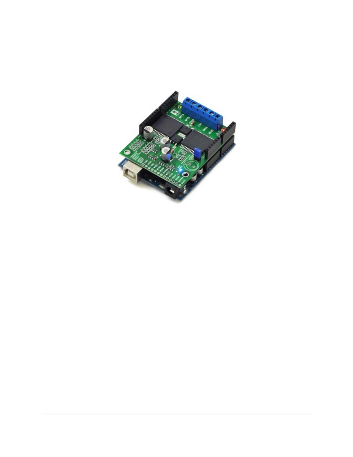
3. Getting Started with an Arduino
As with virtually all other Arduino shields, connections between the Arduino and the motor driver are made via
extended stackable headers that must be soldered to the through-holes along the top and bottom edges of the
shield. This section explains how to use this motor driver as an Arduino shield to quickly and easily add control
of up to two DC motors to your Arduino project. For information on how to use this board as a general-purpose
motor driver controlled by something other than an Arduino, see Section 4.
3.a. What You Will Need
The following tools and components are required for getting started using this motor driver as an Arduino shield:
•An Arduino. Using this product as an Arduino shield (rather than a general-purpose motor driver board)
requires an Arduino [http://www.pololu.com/catalog/product/1616]. This shield should work with all Arduino and
Arduino clones that have the standard Arduino pinout. You will also need a USB cable for connecting your
Arduino to a computer. We have specifically tested this shield (using our Arduino library) with:
◦Arduino Uno [http://www.pololu.com/catalog/product/1616]
◦ Arduino Duemilanove (both with ATmega168 and ATmega328P)
◦Arduino Mega 2560 [http://www.pololu.com/catalog/product/1698]
◦ chipKIT Max32 Arduino-Compatible Prototyping Platform (PIC32-based Arduino clone)
•A soldering iron and solder. The through-hole parts included with the shield must be soldered in before
you can plug the shield into an Arduino or before you can connect power and motors. An inexpensive
soldering iron [http://www.pololu.com/catalog/product/156] will work, but you might consider investing in a
higher-performance soldering iron [http://www.pololu.com/catalog/product/1625] if you will be doing a lot of
work with electronics.
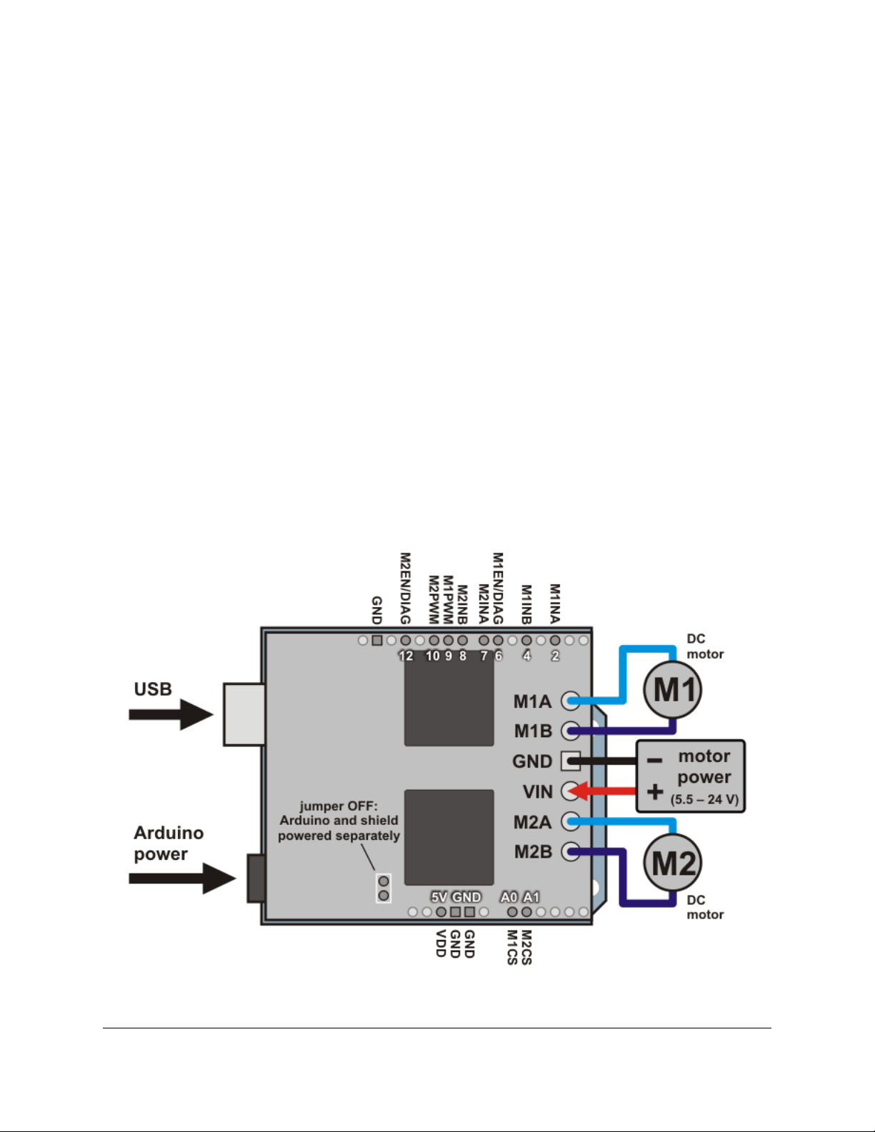
•A power supply. You will need a power supply, such as a battery pack, capable of delivering the current
your motors will draw. See the Power Connections and Considerations portion of Section 3.c for more
information on selecting an appropriate power supply.
•One or two brushed DC motors. This shield is a dual motor driver, so it can independently control two
bidirectional brushed DC motors. See the Motor Connections and Considerations portion of Section 3.c for
more information on selecting appropriate motors.
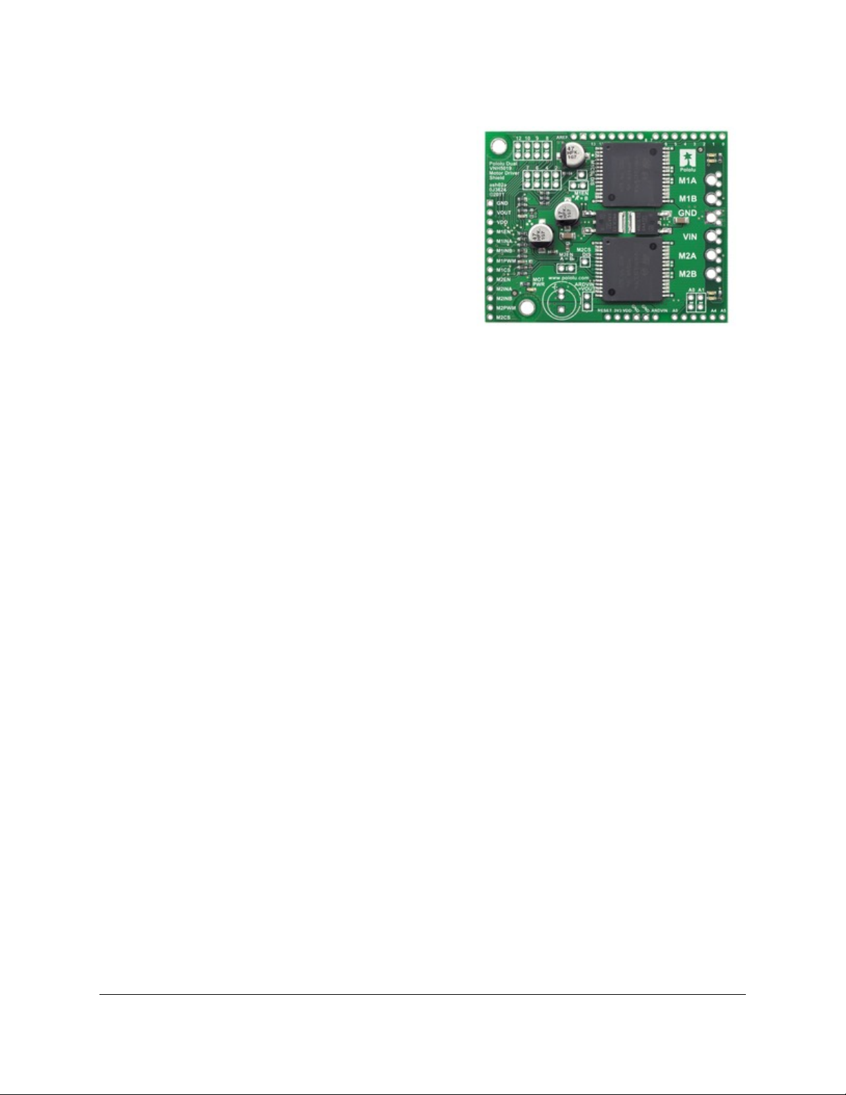
3.b. Assembly for Use as an Arduino Shield
1. Stackable Arduino headers: Before you can use this board as an Arduino shield, you need to solder the
four included Arduino header strips to the set of holes highlighted in red in the picture above. The headers
should be oriented so that the female sockets rest on the top side of the shield and face up while the male pins
protrude down through the board, and the solder connections should be made on the underside of the shield.
Pololu Dual VNH5019 Motor Driver Shield User's Guide © 2001–2011 Pololu Corporation
3. Getting Started with an Arduino Page 6 of 25