DAV TECH DA 600 Product manual
DISPENSING VALVE DA 600
DAV TECH SRL
Via Ravizza, 30 - 36075 Montecchio Maggiore (VI) - ITALY
Tel. 0039 0444 574510 - Fax 0039 0444 574324
Installation and
maintenance guide

Installation and maintenance guide
Index
1 INTRODUCTION pag. 3
2 TECHNICAL DESCRIPTION pag. 3
3 DESCRIPTION AND SPARE PARTS pag. 10
4 INSTALLATION pag. 12
5 OPERATION pag. 15
6 MANITENANCE AND SERVICING pag. 17
7 FAULTS pag. 21
8 TRANSPORT, PACKAGING AND STORAGE pag. 22
9 DISPOSAL pag. 22
DECLARATION OF CONFORMITY pag. 23

DISPENSING VALVE DA 600
pag.3
1 INTRODUCTION
1.1 The manual
The user guide is the document that accompanies the valve from the time of its construction and throughout the period of
use, it is therefore an integral part of the valve. It requires reading the manual before taking any action involving the valve. The
manual must be readily available for use by staff and maintenance of the valve. The user and the attendant use are required
to know the contents of this manual.
Reproduction of any part of this manual, in any form, without the express written permission of DAV Tech. The text and
illustrations in this manual are not binding, the DAV tech reserves the right, at any time and without notice, the right to make
any changes to improve the product or for reasons of character manufacturing or commercial.
1.2 Warranty
The warranty is valid for a period of 12 months from the date of commissioning and no later than 15 months from the
date delivery. The interventions carried out during the warranty period does not extend in any way the validity period of the
guarantee. The seller is not liable for defects caused by normal wear of parts which by their nature are subject to wear.
1.3 Goods receiving
The original configuration of the valve must never be changed.
Upon receipt of the goods, check that:
• The packaging is intact
• The exact correspondence of the material ordered.
2 TECHNICAL DESCRIPTION
2.1 Technical Specification
Model DA 600
Material pressure DA 600-18 max. 50 bar / DA 600 -SY max. 50 bar
Control air pressure: min. 6 bar
Measurements: 145x201x36 mm
Weight: approx. 700 g
Valve body: Special version for applying beads, handhold made from stainless steel, gun body chemically nickel
plated, all wetted parts made from stainless steel or chemically nickel plate
Nozzle: stainless steel
Needle: stainless steel
Gaskets: Viton®(other materials on request)

Installation and maintenance guide
2.2 Purpose of the document
These instructions
> are intended as an important source of information and reference material for personnel who install and operate
the device.
> describe the working procedures, assembly and servicing of the product.
> provide important advice for handling the product safely and efficiently.
2.3 Explanation of symbols
Important information, such as safety instructions, is identified by corresponding symbols.
It is essential to heed this information in order to prevent accidents and damage to the device.
2.4 Intended use
The DA 600 valve has been built according to the EC directive in line with the latest state of the art and the recognised
rules of engineering.
Nevertheless, its use can present risks to the life and limb of the user or third parties, or can impair the machine or
cause other damage.
The DA 600 valve is a needle valve for dispensing material either continuously or intermittently.
WARNING! Risk of inj injury!
This symbol identifies all safety instructions in these Operating/Installation Instructions. Failure to
observe them presents a risk of injury or death. Carefully observe these work safety instructions and
exercise particular caution when you see this symbol.
WARNING! Electrical hazard!
This symbol draws attention to hazardous situations due to electric current. Failure to observe the
safety instructions poses the risk of in jury or death. The work to be carried out must only be performed
by a traine d electrician.
IMPORTANT! This symbol identifies all safety instructions in these Operating/Installation Instructions
which must be observed as failure to do so could result in damage to and/or malfunction of the device.
!
IMPORTANT!
Only use the DA 600 valve for its intended purpose and in an entirely safe operating condition!
This is the only way to ensure operating safety!
!
NOTE! This symbol draws attention to useful tips and other information in these Operating/Installation
Instructions. All such information should be observed in the interests of effective device operation.

DISPENSING VALVE DA 600
pag.5
2.5.1 Modifications or changes
2.4.2 Spare parts, wearing parts and auxiliary materials
Using them in a way that differs from or goes beyond the intended use is considered improper use!
For damage arising from improper use:
> the operator bears sole responsibility.
> the manufacturer accepts no liability.
2.5 Reasonably foreseeable incorrect use
WARNING! Risk of injury!
Using the automatic valve in a way other than intended can lead to serious damage!
IMPORTANT! Do not make any changes or additions without consulting the manufacturer and
obtaining written agreement!
!
IMPORTANT!
Using spare and wearing parts from third third-party manufacturers can present risks.
Only use original parts or parts approved by the manufacturer!
!
IMPORTANT!
The manufacturer accepts no liability for damage arising from the use of spare parts, wearing
parts or auxiliary materials that have n ot been approved by the manufacturer!
!
NOTE!
Under no circumstances may aggressive materials such as acids, alkalis, cleaning agents, chemicals,
poisons, highly flammable or similar substances or gases be used.
Consult the manufacturer if you have any doubt as to whether a material is suitable for use.
NOTE!
Unauthorised modifications or changes invalidate any liability or warranty on the part of the
manufacturer.
Installation and maintenance guide
During use, there is a possible risk of:
> injury to life and limb of the operator or third parties.
> damage to the product itself.
> other damage.
2.6 Risks associated with using the product
2.7 Residual risks
The following risks in particular should be taken into account:
NOTE!
Knowledge of the safety and user instructions in this manual is the basis for safe and fault
fault-free operation.
IMPORTANT!
The Operating Instructions must always be kept at the place of use! The Operating Instructions
must be freely accessible at all times to operators, servicing personnel, etc.
The following must also be observed:
• General and local regulations on accident prevention and environmental protection.
!
WARNING! Risk of injury!
Danger from the device out high high-pressure fluids.
Always wear personal protective equipment when working on the device!
WARNING! Risk of hearing damage!
Hearing damage may result from the volume and length of exposure to noise.
Wear ear protection when working with the device!
WARNING! Danger!
Pay attention to the possibility of residual mechanical and pneumatic energy.
WARNING! Danger from pneumatic energy!
The pneumatic energy can cause severe injury. If a component is damaged, high high-pressure
materials can escape and cause injury and damage!
Therefore:
- Before beginn ing work on the pneumatic system, always depressurise the device first.
- Do not remove safety equipment or disable it by modification.
- Do not set the pressures higher than the values specified in the Operating/Installation Instructions.

DISPENSING VALVE DA 600
pag.7
IMPORTANT!
The product is partly completed machinery. It must only be put into use when it is established that
the machine into which the partly completed machine is intended to be incorporated meets the
specifications of the applicable directives!
!
IMPORTANT!
The device is used in a machine or plant and does not have a dedicated controller.
The user must ensure that the device is integrated in the machine or plant control system in
compliance with the applicable accident prevention regulations.
Note the following in relation to this:
> The machine or plant control system must disconnect all power supply cables in the event of
a power failure or emergency stop. After the power supply is restored, the device must not make
any uncontrolled movements.
!
WARNING! Danger!
In addition to the precautions recommended by the manufacturer, the operator must take
appropriate steps to guard against the risks arising from residual energy.
Personnel must be instructed about the risks and the countermeasures to be taken.
WARNING! Danger!
Danger from pressurised media. Installation, servicing, fault finding, cleaning the device, etc.
must only be done when the device is in an unpr essurised state.
WARNING! Danger!
Pay attention to the possibility of residual electrical energy.
WARNING! Electrical hazard!
The electrical energies can cause severe injury. Electricity presents mortal danger if the insulation
or individual componen ts are damaged.
Therefore:
- Switch the main switch off and secure it against being switched back on before starting any
servicing, cleaning or repair work.
- Before beginning work on the electrical system, always switch off the electricity supply to the
device first.
– Do not remove safety equipment or disable it by modification.
Imperative!
The personal protective equipment listed here must be worn when
working on or with the product.

2.8 Obligations of the operator
The operator is obliged only to allow persons to work with the product who:
> are familiar with the fundamental regulations relating to work safety and accident prevention.
> have been instructed in working with the product, and
> have read and understood these instructions.
The operator must also identify any other hazards that may arise from the special working conditions at the place of use
of the product by carrying out a risk assessment pursuant to Ordinance on Industrial Safety and Health. In relation to the
risk assessment, operating instructions pursuant to Ordinance on Industrial Safety and Health must be prepared, which
combine all further instructions and safety instructions.
The operator will also make the required protective equipment available to the personnel. A list of the necessary personal
protective equipment can be found in chapter 2.9.
NOTE!
The requirements of the EC Directive on the Use of Work Equipment 2009/104/EC must be satisfied.
All persons who are required to work on the product are obliged, before starting work:
> to observe the fundamental regulations relating to work safety and accident prevention.
> to have read and understood these instructions.
> to wear the personal protective equipment according to chapter 2.9.
2.9 Obligations of the operating personnel
IMPORTANT! Only authorised, trained and instructed specialist personnel are permitted to handle
the product.
!
NOTE!
Please contact the manufacturer of the product if you have any unanswered questions!
2.10 Personal protective equipment
Safety goggles!
(to protect the eyes against airborne items and fluids)
Protective gloves!
(to protect the skin against friction, abrasions, aggressive mate rials, punctures and deep
injuries to the hands)
Ear protection!
(to protect against hearing damage when the sound pressure level is above 80
dB (A))
Close-fitting working clothes clothes!
(low tear strength, no wide sleeves, no rings or other jewellery, etc.)
Installation and maintenance guide

NOTE!
The use of personal protective equipment depends on the environment where the device is
used and on the medium being employed. For this reason, also observe the risk assessment of the
workplace prepared by the operator.
All information and instructions for the operation, servicing and cleaning of the device are based on our past experience
and results, and are given to the best of our knowledge.
We reserve the right to make technical modifications in the interest of enhancement of the device described in these
Operating/Installation Instructions.
Translations are also provided to the best of our knowledge. We cannot accept responsibility for errors in translation.
The supplied Italian version of the Operating Instructions remains authoritative.
The descriptions and illustrations may differ from the product supplied. The drawings and diagrams are not to scale.
It is forbidden to pass these Operating/Installation Instructions on to third parties and will result in liability for damages.
A warranty with the following scope is provided for this device:
All such parts as prove to be unfit for use or whose fitness for use is greatly compromised within 24 months for one-
shift, 12 months for two-shift and 6 months for three-shift operation since handover to the purchaser due to a cause
predating this handover – in particular faulty design and defects in materials and workmanship – will be repaired or a
replacement supplied at our discretion free of charge.
The warranty takes the form of replacement or repair of the device or individual parts thereof, at our discretion. Expenses
hereby incurred (transport, toll, labour or material costs) are borne by us, unless the expenses increase because the
device was subsequently brought to a location other than the customer’s premises. These extra expenses are the
customer’s/purchaser’s responsibility.
We provide no warranty for damage caused exclusively or partly by the following:
improper or unsuitable use, incorrect installation and/or putting into operation, natural wear and tear, incorrect handling
and/or servicing, unsuitable coating substances, substitute materials and/or chemical, electrical and/or physical effects,
unless we are responsible for them.
This declaration does not affect statutory rights or the contractual rights stemming from our general terms and
conditions of business.
2.11 Liability and warranty
2.11.1 Warranty
Wearing parts are all parts that come into direct contact with the material and/or are subject to wear and tear due to their
function (e.g. nozzles, needles, air caps, seals, O-rings, sealing screws, pistons, etc.). Such parts are excluded from
warranty and defect claims in so far as they are based on wear and tear. The replacement of a part does not extend the
warranty period of the device.
2.11.2 Wearing parts, lifetime warranty
pag.9
DISPENSING VALVE DA 600

Installation and maintenance guide
3 DESCRIPTION AND SPARE PARTS
3.1 Spare parts DA-600
1
2
8
9
7
7
65
4
3
25
16
17
18
19
21
14
10
11
12
13
22
22 23 24
15
20

pag.11
3.2 Spare parts list DA-600
DISPENSING VALVE DA 600
Ref. Description Code
1.1
1.2
LUER LOCK ADAPTER
M 1/4” GAS LUER LOCK ADAPTER
212351
211307
2 NOZZLE ADAPTER 220083
3 MAIN BODY 510215
4 CONICAL ELEMENT 320081
5 TEFLON COLLAR 640095
6 GUIDE ELEMENT 320082
7 CUP SPRING (X 1 PC) 820060
8 PRESSURE SCREW 320080
9 NEEDLE COMPLETE 112436
10 SPRING 820034
11 REGULATION WASHER 620008
12 NEEDLE REGULATION 220082
13 REGULATION SCREW 610477
14.1
14.2
SWIVEL JOINT M 1/4” GAS
SWIVEL JOINT M 3/8” GAS
220302
220303
15 HANDLE GRIP 910080
16 HANDLE GRIP LEVER 190014
17 HANDLE GRIP SAFETY 500020
18.1
18.2
18.3
FILTER DA-600 - 50 MESHES 320 MICRON
FILTER DA-600 - 100 MESHES 150 MICRON
FILTER DA-600 - 200 MESHES 84 MICRON
530012
530011
530010
19 TEFLON SEAL 640096
20 HANDLE PROTECTION SCREW 610086
21 LEVER SAFETY 320087
22 SCREW (X 1 PC) 610085
23 SCREW 610005
24 CUP SPRING (X 1 PC) 820031
25 CYLINDRICAL PIN 320086
GASKET KIT COMPLETE GASKETKIT-DA600

Installation and maintenance guide
3.3 Dimensions DA-600
4 INSTALLATION
4.1 Assembly
WARNING! Risk of injury!
The pneumatic energy can cause severe injury. If a component is damaged, high high-pressure
materials can escape and cause injury and damage!
The manual valve DA 600 can be used in any position.
The distance between nozzle opening and application level depends on the required application width of the material.
The greater the distance between nozzle opening and application level, the greater the application width of the material.
pag.13
DISPENSING VALVE DA 600
4.2 HOSE INSTALLATION
WARNING! Risk of injury!
It must be ensured that the spray gun is adequately grounded via a conductive material hose,
and is connected into the potential equalisation system. (maximum resistance 10-6 Ω)
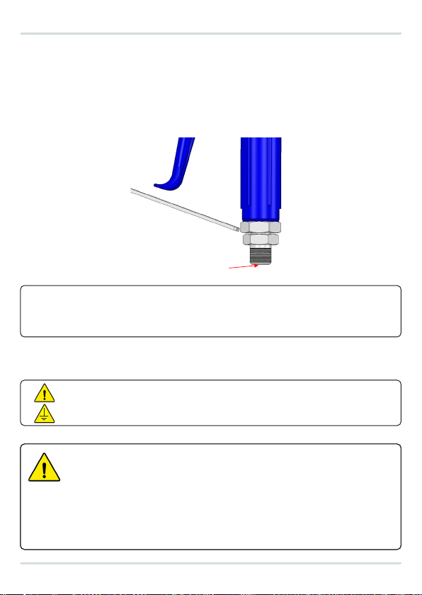
Material is supplied to the spray valve via a separate connection. The connection ports are differentiated as follows:
• Material (transparent or white)
Connection M: to pressure tank or pump
AIRLESS spray gun
Model S720
Copyright ALFRED SCHÜTZE Apparatebau GmbH,
2021. All rights reserved.
23
Doc-ID 1261
4 Installation
Assembly
The manual spray valve Modell S 720 can be used in any position.
The distance between nozzle opening and application level depends on the required application
width of the material. The greater the distance between nozzle opening and application level, the
greater the application width of the material.
Hose installation
Material is supplied to the spray valve via a separate connection. The connection ports are
differentiated as follows (see Fig. 4.2/1):
•Material (transparent or white)
Connection M: to pressure tank or pump
Fig. 4.2/1
WARNING! Risk of injury!
The pneumatic energy can cause severe injury. If a component is damaged, high-pressure
materials can escape and cause injury and damage!
IMPORTANT!
To prevent malfunctions and damage to the manual spray valve and machine or system, it is
essential to ensure that the pressure line is connected up to the correct hose connection on the
spray valve.
Material
IMPORTANT!
To prevent malfunctions and damage to the valve and machine or plant, it is essential to
ensure that the pressure lines are connected up to the correct hose connections on the
valve.
!
Pressure line connection
WARNING! Risk of injury due to compressed air and material pressure!
Only qualified personnel may work on the pressure plant in accordance with the safety regulations.
When working on the pressure plant, be sure to:
> Depressurise the plant before beginning work.
> Not remove or disable safety equipment.
> Not set pressures above the maximum permitted values.
> Install all hoses safely so that the pressure lines ca nnot be damaged by moving machine or
plant components.
> Not put the pressure plant into operation until work is completed.

Installation and maintenance guide
4.3 Installation instructions
The device must be installed in a machine or plant in such a way as to rule out hazards like:
> the escape of high-pressure fluids
> defects in the compressed air supply
> electricity
> malfunctions of the device, machine or plant
> failure or malfunction of plant control
> loud noises or interference with acoustic signals
in the vicinity. To protect persons working on the device, machine or plant, effective safety devices and warning signs
must be put in place. In addition, relevant safety instructions must be incorporated into the Operating/Installation
Instructions for the machine or plant.
WARNING! Risk of injury!
To prevent personal injury and/or property damage, it is essential to observe the following
when installing the device in a machine or plant:
> Material connection:
The screw connection must be secure and airtight!
IMPORTANT!
Only hoses which can withstand the maximum working pressure of the pressure line may be used.
!
Hose installation:
Important: Other connections must be correctly assembled!
AIRLESS spray gun
Model S720
Copyright ALFRED SCHÜTZE Apparatebau GmbH,
2021. All rights reserved.
24
Doc-ID 1261
Pressure line connection
Installing the hose:
➔Material connection:
The screw connection must be secure and airtight!
Important: Other connections must be correctly assembled!
WARNING! Risk of injury!
It must be ensured that the spray gun is adequately grounded via a conductive material hose,
and is connected into the potential equalisation system.
(maximum resistance 10-6 Ω)
WARNING! Risk of injury due to material pressure!
Only qualified personnel may work on the pressure plant in accordance with the safety
regulations.
When working on the pressure plant, be sure to:
➔Depressurise the plant before beginning work.
➔Not remove or disable safety equipment.
➔Not set pressures above the maximum permitted values.
➔
Install all hoses safely so that the pressure lines cannot be damaged by moving machine
or plant components.
➔Not put the pressure plant into operation until work is completed.
IMPORTANT!
Only hoses which can withstand the maximum working pressure of the pressure line may be
used.
4.4 Putting into operation
WARNING! Risk of injury!
Only trained qualified personnel may put the machine or plant into operation in accordance
with the safety and accident preve ntion regulations.

pag.15
>Ensure that no tools or other foreign bodies are inside the machine or plant.
>Check that the device and all other parts are secure.
>Check that all connections are on the correct ports and are secure.
>Check that the set pressures correspond to the ratings and connection values of the device.
>Check that safety devices are working.
1. Switch on power supply.
2. Switch on material flow.
3. Turn on device at plant controller.
4. Check that device is functioning and operating correctly.
5. Check that device is within all the specified set value ranges.
Once it has been established that the device is functioning perfectly, the device may be operated in accordance with all
accident prevention regulations.
DISPENSING VALVE DA 600
Observe the following before putting the machine or plant into operation:
WARNING! Danger from material and substances!
There is a risk of coming into contact with or absorbing coating substances and/or cleaning fluids.
There is also a risk of inhaling fumes from fluids. Under some circumstances, this can cause lasting
damage.
Always wear personal protective equipment when working on the device!
Make sure there is enough forced or natural ventil ation.
Obtain medical advice if symptoms are noted!
To prevent disruptions, device function must be checked regularly by trained supervisors.
5.1 General and safety instructions for operation
5 OPERATION
IMPORTANT!
In the event of faults or irregularities, shut down the plant immediately and inform the local person in charge.
!
If device faults cannot be corrected (see chap. 7 “Faults”), inform the manufacturer’s Customer Service.
Only deploy instructed personnel for regular cleaning.
The device presents the following hazards during operation:
WARNING! Risk of injury!
Danger from the device out high high-pressure fluids. Always wear personal protective
equipment when working on the device device!
Installation and maintenance guide
> If the material is kept pressurised with no contact with the outside air, it can remain in the valve during long periods
without operation.
> Only clean, filtered material may be used.
5.2 Operating instructions
WARNING! Risk of hearing damage!
Hearing damage may result from the volume and length of exposure to noise.
Wear ear protection when working with the device!
WARNING! Risk of injury!
Housing parts with sharp edges and pointed corners can cause skin abrasions.
Wear protective gloves when working on the device!
WARNING! Danger!
If the spray parameters are not adequately adjusted, there is a risk of inhalation, contact with or
absorption of coating substances or cleaning fluids.
Always wear personal protective equipment when working on the device!
AIRLESS spray gun
Model S720
Copyright ALFRED SCHÜTZE Apparatebau GmbH,
2021. All rights reserved.
28
Doc-ID 1261
Operating instructions
➔If the material is kept pressurised with no contact with the outside air, it can remain in the
valve during long periods without operation.
➔Only clean, filtered material may be used.
Fig. 5.2/1
WARNING! Danger!
If the spray parameters are not adequately adjusted, there is a risk of inhalation, contact with or
absorption of coating substances or cleaning fluids.
Always wear personal protective equipment when working on the device!
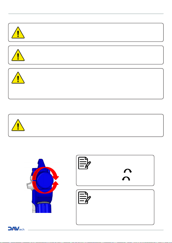
NOTE!
The flow of material can be adjusted to suit individual requirements by turning the regulating
screw (Item No. 8.1) (see Fig. 5.2/1):
Turn screw to the right: to reduce the material flow
Turn screw to the left: to increase the material flow
NOTE!
The illustrations in these instructions may differ slightly from the actual version of the device.
Incorrect handling can damage the nozzle and nozzle needle. Only reduce the material flow (by
turning the regulating screw to the right) while the material is being dispensed. Once the nozzle
closes, do not turn the regulating screw any further to the right.
NOTE! The flow of material can be adjusted
to suit individual requirements by turning the
regulating screw:
Turn screw to the right:
to reduce the material flow
Turn screw to the left:
to increase the material flow
NOTE! The illustrations in these instructions
may differ slightly from the actual version of
the device. Incorrect handling can damage
the nozzle and nozzle needle. Only reduce
the material flow (by turning the regulating
screw to the right) while the material is being
dispensed. Once the nozzle closes, do not turn
the regulating screw any further to the right.
WARNING! Danger from material and substances!
There is a risk of coming into contact with or absorbing coating substances and/or cleaning fluids.
There is also a risk of inhaling fumes from fluids. Under some circumstances, this can cause lasting
damage.
Always wear personal protective equipment when working on the device!
Make sure there is enough forced or natural ventilation.
pag.17
DISPENSING VALVE DA 600
1. Switch on power supply.
2. Switch on material flow.
3. Turn on device at plant controller.
4. Check that device is functioning and operating correctly.
5. Check that device is within all the specified set value ranges.
5.4 Switching off
1. Shut down device at plant controller.
2. Switch off the material flow.
3. Switch off power supply.
5.5 Shutdown
Before shutting the device down for an extended period, the following steps must be taken in accordance with the
safety regulations:
> Switch off device and prevent it from being switched back on.
> Remove material residue from the device.
> Clean device inside and out.
5.3 Switching on
WARNING! Risk of injury!
Only trained qualified personnel may switch the device on and off in accordance with the
safety and accident prevention regulations.
6 MAINTENANCE AND SERVICING
Safety instructions
WARNING! Risk of injury!
Only perform servicing and cleaning work on the device when the device and plant are at a
standstill!
WARNING! Risk of injury!
Improper handling of the device carries the risk of severe personal injury and serious damage.
Therefore, servicing and cleaning work must only be carried out by qualified personnel or
personnel who have been specially trained in these tasks (training to be documented)!

Installation and maintenance guide
Servicing
The manual spray valve is a high-quality precision device which will usually operate fault-free and without any servicing
if handled correctly, provided that only clean, filtered material is used. It is also essential that the control air be clean and,
ideally, supplied to the spray valve lightly oiled. Individual operating conditions and the properties of various materials
require a minimum of care to be given to the device.
Before beginning any servicing work:
> Put on personal protective equipment.
> Switch off device and prevent it from being switched back on.
> Switch off pressure plant and prevent it from being switched back on. Depressurise all supply pressure lines and
disconnect them from the device.
NOTE!
Remaining spray media should be dealt with at appropriate time intervals.
Cleaning
The valve must be cleaned when
> it is soiled by use
> a different material is to be used
> wearing parts have to be replaced.
This applies in particular to the nozzle needle, the sealing bush and the nozzle.
IMPORTANT!
Do not use any sharp sharp-edged, metallic aids for external cleaning; only use soft brushes.
!
WARNING! Risk of injury!
There is a risk that components will be ejected! The valve must only be opened after the
device has bee n depressurised and is not operational!
WARNING! Danger from material and substances!
There is a risk of coming into contact with or absorbing coating substances and/or cleaning fluids.
There is also a risk of inhaling fumes from fluids. Under some circumstances, this can cause lasting
damage. Always wear personal protective equipment when working on the device!
Make sure there is enough forced or natural ventil ation.
Obtain medical advice if symptoms are noted!
WARNING! Danger!
The pressure spring inside the spray mechanism of the spray gun is compressed, and can be
ejected from the spray gun during maintenance or c leaning work.
6.1 General and safety instructions for maintenance and servicing

pag.19
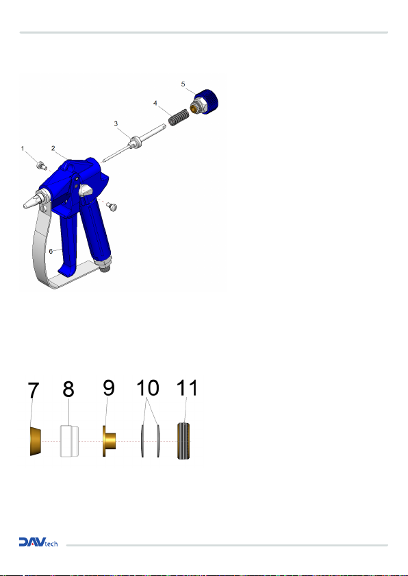
1. Depressurise all connections and stop the
material supply!
2. Undo the locking screw / regulating screw
(5) (Caution: The locking screw / regulating
screw is under spring tension!)
3. Make sure that the pressure spring (4) does
not get lost.
4. Withdraw the nozzle needle (3) and unscrew
the nozzle (1).
5. Lightly grease the new nozzle needle (3)
and push it into the body of the handle (2).
Then remove any remaining grease from the
needle tip.
6. Screw the new nozzle (1) into the body of the
handle (2).
7. Only now should the locking screw /
regulating screw (5) be screwed back onto
the body of the handle (2). Make sure that
the pressure spring (4) is installed again.
8. Perform a functional test of the device after
changing the nozzle and needle!
NOTE!
The device should be checked regularly for wear. It is not possible to specify when wear and
tear may occur, since this depends on the material being processed, the switching frequency,
and the conditions under which the device is used.
NOTE!
When installing nozzles and nozzle needles that have already been in use, they must first be
cleaned of all deposits and material residues. Material residues in nozzles can result in leaks
in the nozzle needle system, while nozzle needles with hardened material residue s can cause
damage to the sealing elements in the spray valve.
DISPENSING VALVE DA 600
IMPORTANT!
Using spare and wearing parts from third party manufacturers can present risks. Only use original parts
or parts approved by the manufacturer!
!
IMPORTANT!
Always install a new nozzle (1 if fitted ) and nozzle needle 3 ) at the same time.
!
6.2 Replacing the nozzle needle and the nozzle
AIRLESS spray gun
Model S720
Copyright ALFRED SCHÜTZE Apparatebau GmbH,
2021. All rights reserved.
32
Doc-ID 1261
Replacing the nozzle needle and the nozzle (S720-KL/LV only)
Fig. 6.2/1
1. Depressurise all connections and stop the material supply!
2. Undo the locking screw / regulating screw (5)
(Caution: The locking screw / regulating screw is under spring tension!)
3. Make sure that the pressure spring (4) does not get lost.
4. Withdraw the nozzle needle (3) and unscrew the nozzle (1).
5. Lightly grease the new nozzle needle (3) and push it into the body of the handle (2). Then
remove any remaining grease from the needle tip.
6. Screw the new nozzle (1) into the body of the handle (2).
7. Only now should the locking screw / regulating screw (5) be screwed back onto the body
of the handle (2). Make sure that the pressure spring (4) is installed again.
8. Perform a functional test of the device after changing the nozzle and needle!
IMPORTANT!
Always install a new nozzle (1 - if fitted) and nozzle needle (3) at the same time.
NOTE!
When installing nozzles and nozzle needles that have already been in use, they must first be
cleaned of all deposits and material residues. Material residues in nozzles can result in leaks
in the nozzle-needle system, while nozzle needles with hardened material residues can cause
damage to the sealing elements in the spray valve.
Installation and maintenance guide
AIRLESS spray gun
Model S720
Copyright ALFRED SCHÜTZE Apparatebau GmbH,
2021. All rights reserved.
34
Doc-ID 1261
Replacing the seal
Fig. 6.3.1/1
1. Proceed as described up to Section 3 in ch. 6.3.
2. Unscrew the nozzle.
3. Using a valve needle unit (3) as an installation aid, install the following parts in the given
order: Thrust washer (11), 2 plate springs (10 = hollow sides against each other), guide for
plate springs (9), PTFE collar (8) and pressure cone (7) are fitted in this order and are then
inserted in the gun body so that the complete sealing unit is located in the front area of the
sealing chamber of the gun.
4. As when adjusting the seal, the pressure on the collar and the pressure cone is increased
by turning the pressure screw (11) in a clockwise direction.
5. Because the nozzle has been unscrewed and removed, you can check by inserting from
the front whether the needle requires a little pressure to pass through the PTFE collar but
still passes smoothly.
6. The spray gun is then re-assembled by carrying out the same steps in reverse order.
1. If there are any leaks in the sealing area
(this can be seen by spray material escaping
between the trigger (6) and the main body
(2)), you should depressurise the liquid in
the system.
2. The unscrew the adjusting unit (5) from the
gun. Pull out the valve needle unit (3) with
the pressure spring (4)
(Important: (The adjusting unit is under
spring tension!)
3. Remove the two shoulder screws (1) from
the trigger (6)
4. You can now use a screwdriver to turn the
sealing screw (5.1.2) slightly in a clockwise
direction. This increases the pressure on the
PTFE collar (and the pressure cone). The
pressure screw must be turned clockwise in
small increments. Repeatedly re-insert the
needle to check whether the needle requires
some pressure to pass through the PTFE
collar but still passes smoothly. The needle
must not stick.
5. If the PTFE collar (8) is no longer completely
airtight due to wear and tear, it must be
replaced (see ch.6.3.1)
1. Proceed as described up to Section 3 in ch. 6.3.
2. Unscrew the nozzle.
3. Using a valve needle unit (3) as an installation
aid, install the following parts in the given
order: Thrust washer (11), 2 plate springs (10
= hollow sides against each other), guide for
plate springs (9), PTFE collar (8) and pressure
cone (7) are fitted in this order and are then
inserted in the gun body so that the complete
sealing unit is located in the front area of the
sealing chamber of the gun.
4. As when adjusting the seal, the pressure on the
collar and the pressure cone is increased by
turning the pressure screw (11) in a clockwise
direction.
5. Because the nozzle has been unscrewed and
removed, you can check by inserting from
the front whether the needle requires a little
pressure to pass through the PTFE collar but
still passes smoothly.
6. The spray gun is then re-assembled by carrying
out the same steps in reverse order.
6.3 Adjusting and replacing the seal
6.3.1 Replacing the seal
AIRLESS spray gun
Model S720
Copyright ALFRED SCHÜTZE Apparatebau GmbH,
2021. All rights reserved.
33
Doc-ID 1261
Adjusting and replacing the seal
Fig. 6.3/1
1. If there are any leaks in the sealing area (this can be seen by spray material escaping
between the trigger (6) and the main body (2)), you should depressurise the liquid in the
system.
2. The unscrew the adjusting unit (5) from the gun. Pull out the valve needle unit (3) with the
pressure spring (4)
(Important: (The adjusting unit is under spring tension!)
3. Remove the two shoulder screws (1) from the trigger (6)
4. You can now use a screwdriver to turn the sealing screw (5.1.2) slightly in a clockwise
direction. This increases the pressure on the PTFE collar (and the pressure cone). The
pressure screw must be turned clockwise in small increments. Repeatedly re-insert the
needle to check whether the needle requires some pressure to pass through the PTFE collar
but still passes smoothly. The needle must not stick.
5. If the PTFE collar (8) is no longer completely airtight due to wear and tear, it must be
replaced (see ch.6.3.1)
Table of contents
Other DAV TECH Control Unit manuals

DAV TECH
DAV TECH DA 400 Product manual

DAV TECH
DAV TECH DAS 90 Product manual

DAV TECH
DAV TECH DA 400 EVO Product manual

DAV TECH
DAV TECH DAV 150 Product manual

DAV TECH
DAV TECH DAV 300 MAN Product manual

DAV TECH
DAV TECH DAS 50N Product manual

DAV TECH
DAV TECH DAS 30 Product manual

DAV TECH
DAV TECH DA 400 EV Product manual

DAV TECH
DAV TECH DA 250 Product manual


