
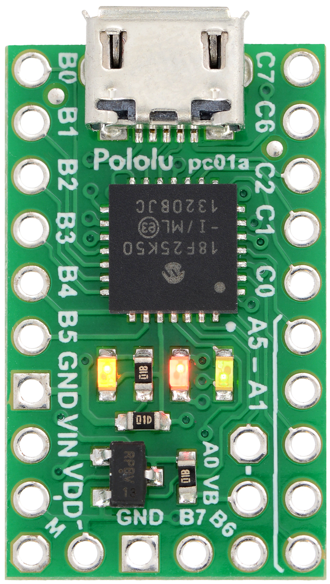
LEDs
The P-Star 25K50 Micro has three indicator LEDs. These LEDs are connected in the same way on all
P-Stars.
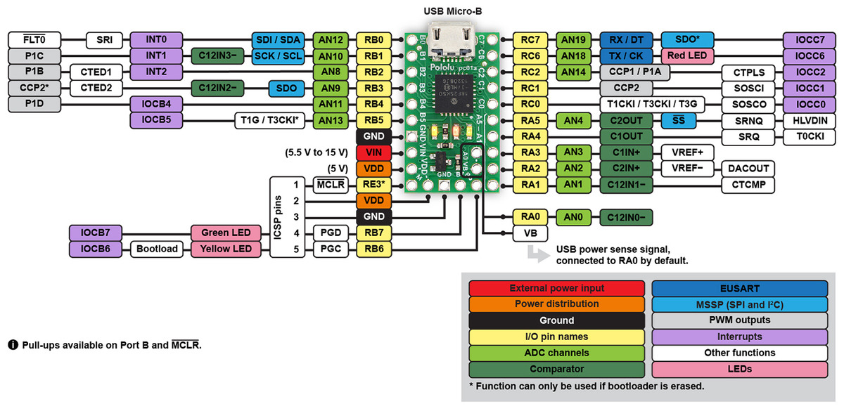
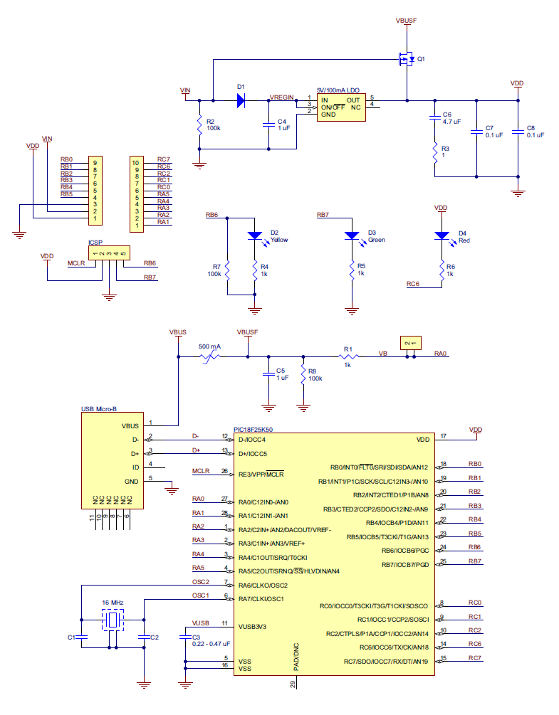
The yellow LED is connected to RB6. Driving this pin high turns on the LED. In bootloader mode, the
bootloader drives this line high to turn on the LED (see Section 6.4) but never drives it low. If this line
is high when the microcontroller starts up, the microcontroller will go into bootloader mode. A button
can be connected to RB6 as described in Section 5.2. RB6 has an on-board pull-down resistor to
ensure that its voltage goes all the way down to 0 V when not being driven.
The green LED is connected to RB7, and lights when the pin is driven high. In bootloader mode, the
bootloader drives this line high to turn on the LED (see Section 6.4) but never drives it low.
The red LED is connected to RC6, and lights when the pin is driven low. RC6 is the microcontroller’s
serial TX line, so the red LED serves as an indicator for when the board is transmitting serial data. If
you are not using serial, the LED can be used as a normal LED. To avoid interference with connected
serial devices, the bootloader does not use this LED.
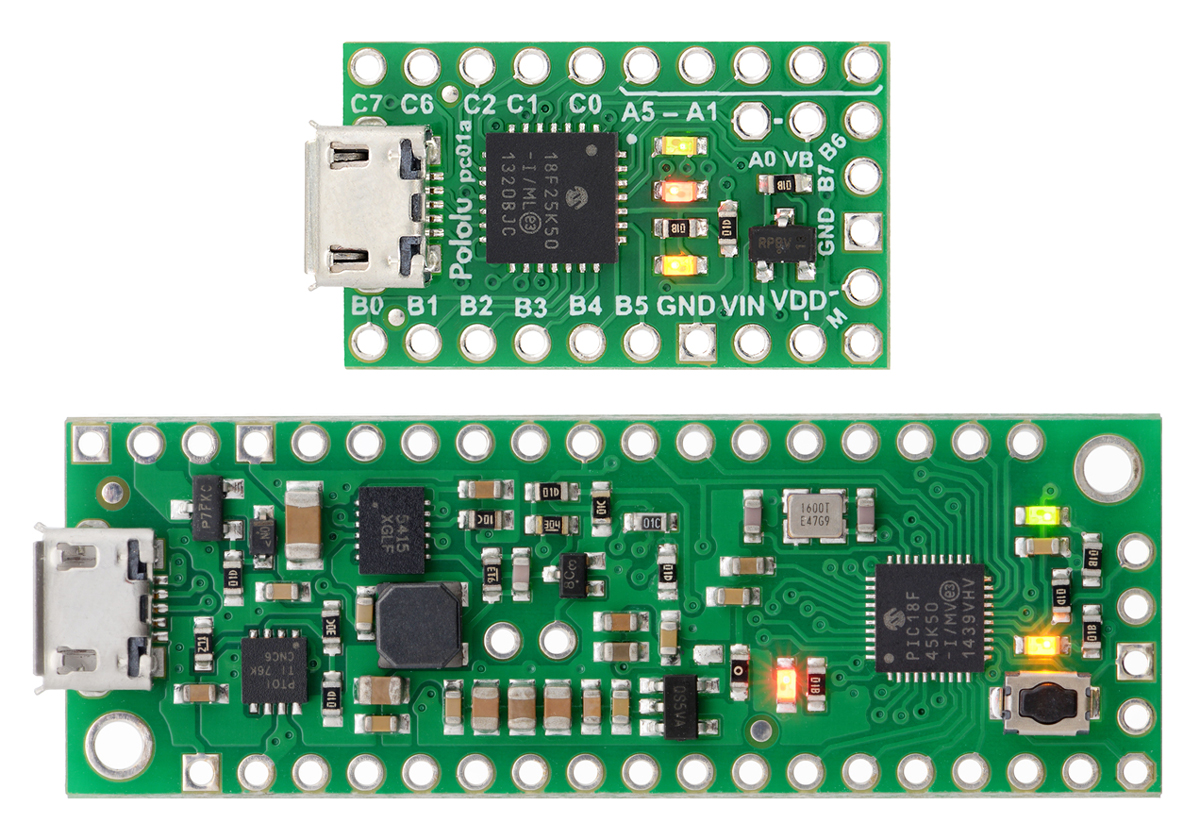
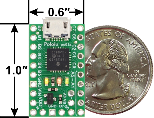
Connectors
The P-Star includes a USB Micro-B connector that can be used to connect to a computer’s USB port
via a USB A to Micro-B cable [https://www.pololu.com/product/2072] (not included). The USB connection
can be used to transmit and receive data from the computer, and a preloaded USB bootloader makes
it possible to program the board over USB. The USB connection can also provide power to the P-Star.
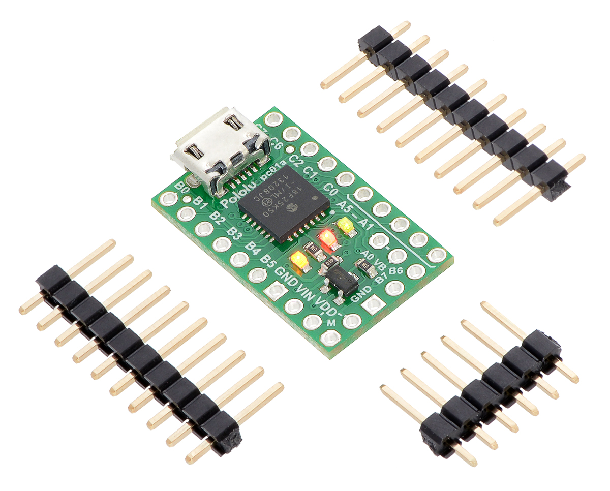
The board also has five pins arranged so that they can be directly plugged into a standard In-Circuit
Serial Programming (ICSP) connector, such as the one found on the PICkit 3. More information about
programming with the PICkit 3 can be found in Section 7. The five pins are: MCLR, VDD, ND, RB7/
P D, and RB6/P C. The MCLR pin is pin 1.
Power
The P-Star 25K50 Micro can either be powered directly from the USB 5 V supply or from a separate
source on the VI pin. The board features a power selection circuit that allows both USB and VIN to
be connected at the same time; if this is done, the P-Star will draw power from VIN.
USB power input: The P-Star can be powered from the USB 5 V bus voltage (VBUS) if it is connected
to a USB cable. It will draw power from USB only if VIN is disconnected. A resettable PTC fuse on
VBUS makes it less likely for the P-Star (and the connected computer or other device) to be damaged
if too much current is drawn from the USB connection.
VI power input: The P-Star can be powered from VIN if you connect a 5.5 V to 15 V power
Pololu P-Star User’s uide © 2001–2019 Pololu Corporation
3. P-Star 25K50 Micro Page 6 of 46


