manuals.online logo
Brands
  1. Home
  2. •
  3. Brands
  4. •
  5. Polytron
  6. •
  7. Media Converter
  8. •
  9. Polytron PSG 510-10 TAP User manual

Polytron PSG 510-10 TAP User manual

Beschreibung
Das SAT Multischalter Zubehör wurde speziell für größere
Kaskadieranlagen in Verbindung mit Multischaltern und
Verstärkern entwickelt.
Die Abzweiger verteilen 4 SAT-Ebenen und ein
terrestrisches Signal und verfügen je nach Typ über 10 dB
oder 15 dB Auskoppeldämpfung. Der DC-Durchgang
maximal 2 A dient der LNB-Spannungsversorgung.
Wenn ein Abzweiger am Ende eines Kaskadensystems
verwendet wird, so muss dieser mit DC-geblockten
Endwiderständen abgeschlossen werden!
Die 2-fach und 4-fach Verteiler dienen der Verteilung von 4
SAT-Ebenen und einem terrestrischen Signal auf jeweils 2
oder 4 gleichwertige Ausgänge. Der DC-Durchgang
maximal 1 A dient der LNB-Spannungsversorgung.
Wichtige Hinweise:
Bitte überprüfen Sie die Anlage vor Inbetriebnahme auf
evtl. Kurzschlüsse der Koaxial-Kabel. Der Montage-
untergrund sollte:
eben, schwer entflammbar und staubfrei
gegen Feuchtigkeit geschützt
nicht direkter Sonneneinstrahlung ausgesetzt
und nicht in unmittelbarer Nähe von Wärmequellen sein.
Die Lüftungsschlitze der Netzteile dürfen nicht verdeckt
sein. Es ist darauf zu achten, dass die Eingangspegel der
SAT-Ebenen möglichst gleich hoch sind. Alle Installationen
und Anbringen von Montageteilen sollten nur durchgeführt
werden, wenn die Anlage vom Stromnetz getrennt ist!
Kurzschlüsse vermeiden.
Die Hinweise zum Betrieb des Gerätes sind zu beachten.
SAT Multischalter Zubehör
SAT multiswitch accessories
zur Verteilung von 4 SAT-ZF-Ebenen und
terrestrischen Signalen
for distribution of 4 SAT-IF-polarizations
and terrestrial signals
Abzweiger beispielhaft / Tap exemplary
Verteiler für Kaskadiersysteme
Splitters for cascadable systems
Verteiler 2-fach / 2-way Splitter
Verteiler 4-fach / 4-way Splitter
Abzweiger für Kaskadiersysteme
Taps for cascadable systems
Abzweiger 10 dB / Tap 10 dB
Abzweiger 15 dB / Tap 15 dB
Bedienungsanleitung
User manual
V1
Technische Daten / Specifications
Splitters
Typ / Type
2-fach / 2-way
4-fach / 4-way
Eingangsfrequenz /
SAT
950...2150 MHz
Input frequency
Terr.
5...862 MHz
Eingänge / Inputs
4 SAT, 1 TERR
Ausgänge / Outputs
2x
4 SAT, 1 TERR
4x
4 SAT, 1 TERR
Durchgangsdämpfung /
SAT
4,5 dB
8,5 dB
Through loss
Terr.
4,0 dB
8,0 dB
Entkopplung Terr./SAT / Isolation Terr./SAT
40 dB typ.
Entkopplung H/V / Isolation H/V
35 dB typ.
Rückflussdämpfung / Return loss
SAT
15 dB typ.
Terr.
DC Durchgang / DC pass OUT - IN
1 A max.
Abmessungen (B x H x T) / Dimensions (W x H x D)
183 x 125 x 54 mm
270 x 125 x 54 mm
Technische Daten / Specifications
Taps
Typ / Type
10 dB tap loss
15 dB tap loss
Eingangsfrequenz /
SAT
950...2150 MHz
Input frequency
Terr.
5...862 MHz
Eingänge / Inputs
4 SAT, 1 TERR
Ausgänge / Outputs
4 SAT, 1 TERR
Abzweig / Taps
4 SAT, 1 TERR
Durchgangsdämpfung /
SAT
1,8 dB
1,2 dB
Through loss
Terr.
1,5 dB
1,0 dB
Abzweigdämpfung/
Tap loss
SAT
8 … 12 dB
13 … 17 dB
Terr.
10 dB
15 dB
Entkopplung Terr./SAT / Isolation Terr./SAT
40 dB typ.
Entkopplung H/V / Isolation H/V
35 dB typ.
Rückflussdämpfung / Return loss
SAT
13 dB typ.
Terr.
15 dB typ.
DC Durchgang / DC pass OUT - IN
2 A max.
Abmessungen (B x H x T) / Dimensions (W x H x D)
183 x 125 x 54 mm
Copyright © Polytron-Vertrieb GmbH
All rights reserved to the editor. All information is provided
without guarantee and is subject to changes.
Polytron-Vertrieb GmbH
Langwiesenweg 64-71, 75323 Bad Wildbad, Germany
0902521
Description
The SAT multiswitch accessories were specially developed
for larger cascading systems in connection with
multiswitches and amplifiers.
The Taps distributes 4 SAT polarizations and a terrestrial
signal and provides 10 dB or 15 dB tap loss, depending on
the type. The DC pass through for LNB power supply is
maximum 2 A.
If a tap is used at the end of a cascading system the trunk
outputs need to be terminated with DC-blocked
terminators.
The 2 way and 4 way Splitters are used to split 4 SAT
polarizations and a terrestrial signal to 2 or 4 equivalent
outputs each. The DC pass through for LNB power supply
is maximum 1 A.
Important Notes:
Please check the coaxial cable regarding short circuit
before starting. The mounting ground should be:
even and flame proof
dust-free
protected against humidity
not under direct impact of sunlight
not adjacent to heating sources
The ventilation slots of the associated power supply unit
may not be covered.
Pay attention to the input levels of the SAT-polarizations
having the equivalent level. All installation and fixing of
components should only be executed when the units are
disconnected from the mains supply. Avoid short-circuits!
The instructions for operating the device must be observed.
Mounting and safety instructions
Attention
The rated voltage on the device must be corresponding with the mains
voltage. The instructions for operating the device must be observed.
Grounding and potential equalization
Please establish grounding and perform potential equalization before
initial startup.
Connection cable
Always install connection cables with a loop so that no condensed water
can penetrate along the cable.
The coaxial DC power supply connection cable must have an inner
conductor diameter of at least 1mm.
Select installation site
Install only on a solid, plane and at most fire-resistant surface. It's
imperative to observe the mounting position!
Moisture
Protect the device from high humidity, dripping and splashing water.
Operating environment according to the specified IP protection class.
Caution! Danger of life!
According to the currently valid version of EN 60728-11, coaxial
receiving and distribution systems must meet the safety requirements
regarding grounding, potential equalization, etc., otherwise damage to
the product, fire or other hazards may occur. Electrical fuses may only
be replaced by authorised specialist persons. For the replacement of
electric fuses, only same type and amperage have to be used. In case of
damage the device has to be taken out of service.
Mounting and service works
May be only done by authorized staff according to the rules of
technology. Devices have to be switched off before starting any
maintenance or service work. In order to guarantee interference
immunity, all device covers must be screwed tight again after opening.
Thunderstorm
Do not carry out maintenance or repair work on the device due to higher
risk of lightning strike.
Ambient temperature
Operation and storage only within the specified temperature range.
Termination
Not used receiver and trunk line outputs have to be terminated with 75
Ohm resistors.
Attention
Damages caused by faulty connections and/or improper handling
are excluded from any liability.
Recycling
All of our packaging materials are fully recyclable.
Montage- und Sicherheitshinweise
Achtung
Die auf dem Gerät angegebene Nennspannung muss mit der
örtlichen Netzspannung übereinstimmen. Die Hinweise zum
Betrieb des Gerätes sind zu beachten.
Erdung und Potentialausgleich
Vor Erstinbetriebnahme die Erdung herstellen und den
Potenzialausgleich durchführen.
Anschlusskabel
Stolperfrei mit einer Schlaufe verlegen, damit das
Kondenswasser- und/oder bei Schwitzwasserbildung kein
Wasser ins Gerät läuft sondern auf den Boden tropft.
Das koaxiale DC-Netzteilanschlusskabel muss über einen
Innenleiter-Durchmesser von mindestens 1mm verfügen.
Aufstellungsort wählen
Montage nur auf eine feste, ebene und möglichst
brandresistente Oberfläche. Für freie Luftzirkulation sorgen und
unbedingt die richtige Einbaulage beachten!
Feuchtigkeit
Tropf-, Spritzwasser und hohe Luftfeuchtigkeit schaden dem
Gerät. Betriebsumgebung laut spezifizierter IP-Schutzklasse.
Achtung Lebensgefahr!
Gemäß der aktuell gültigen Fassung der EN 60728-11 müssen
koaxiale Empfangs- und Verteilanlagen den
Sicherheitsanforderungen bezüglich Erdung, Potentialausgleich
etc. entsprechen, sonst können Schäden am Produkt, ein Brand
oder andere Gefahren entstehen. Sicherungen werden nur von
autorisiertem Fachpersonal gewechselt. Es dürfen nur
Sicherungen des gleichen Typs eingesetzt werden. Bei
Beschädigung ist das Gerät außer Betrieb zu nehmen.
Installations- und Servicearbeiten
dürfen nur von autorisiertem Fachpersonal entsprechend den
Regeln der Technik durchgeführt werden. Vor Beginn der
Servicearbeiten die Betriebsspannung abschalten und gegen
Wiedereinschalten sichern. Um die Störstrahlsicherheit zu
garantieren, müssen sämtliche Geräteabdeckungen nach
Öffnen wieder fest verschraubt werden.
Gewitter
Aufgrund erhöhter Blitzschlaggefahr keine Wartungs- und/oder
Installationsarbeiten am Gerät oder an der Anlage vornehmen.
Umgebungstemperatur
Betrieb und Lagerung nur innerhalb des spezifizierten
Temperaturbereichs.
Abschluss / Terminierung
Nicht benutzte Teilnehmer-/ Stammleitungsausgänge sind mit
75 Ohm-Widerständen abzuschließen.
Achtung
Schäden durch fehlerhaften Anschluss und/oder
unsachgemäße Handhabung sind von jeglicher Haftung
ausgeschlossen.
Recycling
Unser gesamtes Verpackungsmaterial ist vollständig
recyclingfähig.
This manual suits for next models

3

Other Polytron Media Converter manuals

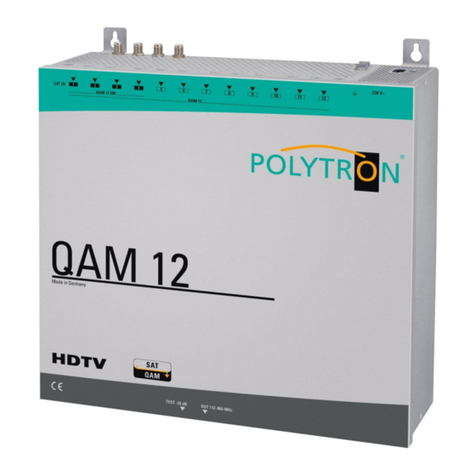
Polytron HDS 2 C01 User manual

Polytron

Polytron HDS 2 C01 User manual

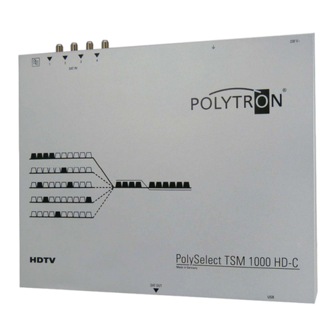
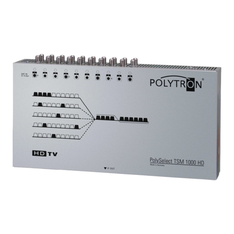
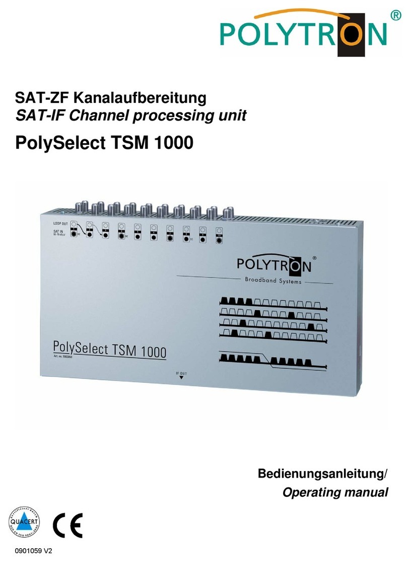
Polytron PolySelect TSM 1000 User manual

Polytron

Polytron PolySelect TSM 1000 User manual

Polytron HDM 2 C/IP User manual

Polytron

Polytron HDM 2 C/IP User manual

Polytron OPM-LNB circ 032 User manual

Polytron

Polytron OPM-LNB circ 032 User manual

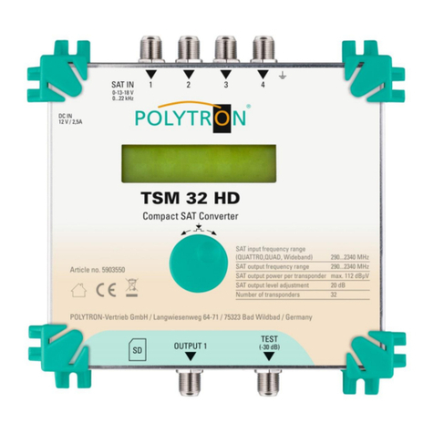
Polytron TSM 32 HD User manual

Polytron

Polytron TSM 32 HD User manual

Polytron TSM 1000 HD-C User manual

Polytron

Polytron TSM 1000 HD-C User manual

Polytron TST-B User manual

Polytron

Polytron TST-B User manual

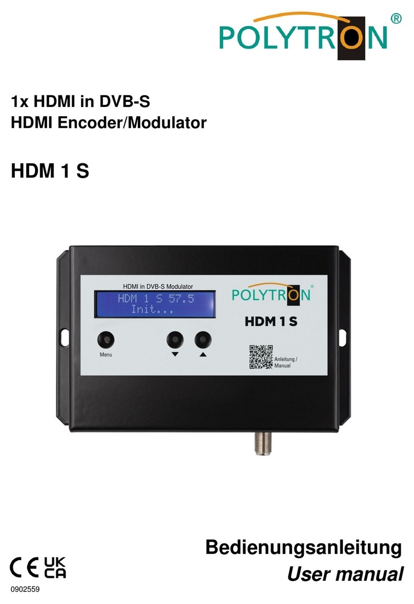
Polytron HDM 1 S User manual

Polytron

Polytron HDM 1 S User manual

Polytron SPM-TDT-Q User manual

Polytron

Polytron SPM-TDT-Q User manual

Polytron QAM 12 LAN User manual

Polytron

Polytron QAM 12 LAN User manual

Polytron OPM-LNB 032 User manual

Polytron

Polytron OPM-LNB 032 User manual

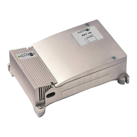
Polytron AVT 1 Q User manual

Polytron

Polytron AVT 1 Q User manual

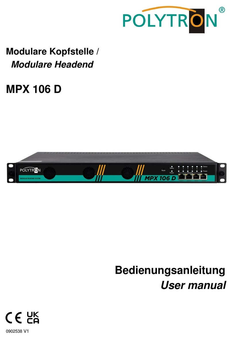
Polytron MPX 106 D User manual

Polytron

Polytron MPX 106 D User manual

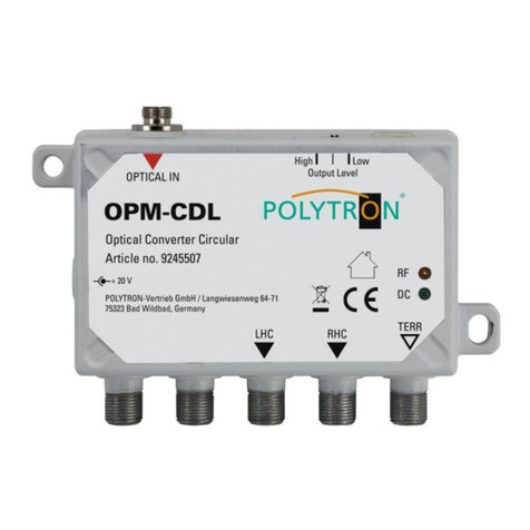
Polytron OPM-CDL User manual

Polytron

Polytron OPM-CDL User manual

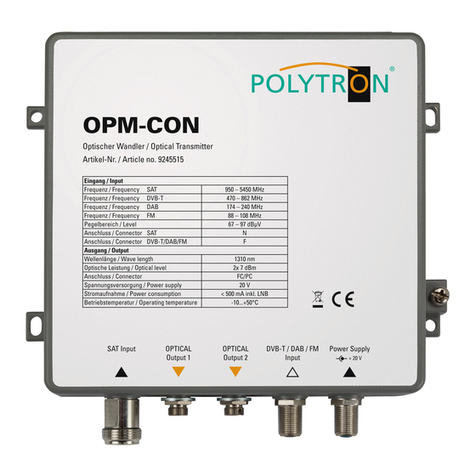
Polytron OPM-CON User manual

Polytron

Polytron OPM-CON User manual

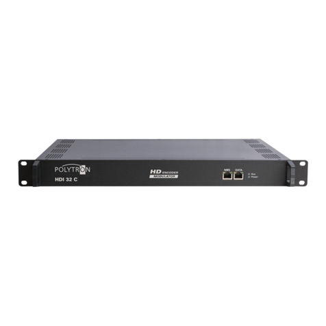
Polytron HDI 32 C User manual

Polytron

Polytron HDI 32 C User manual

Polytron PolySelect TSM 1000 HD User manual

Polytron

Polytron PolySelect TSM 1000 HD User manual

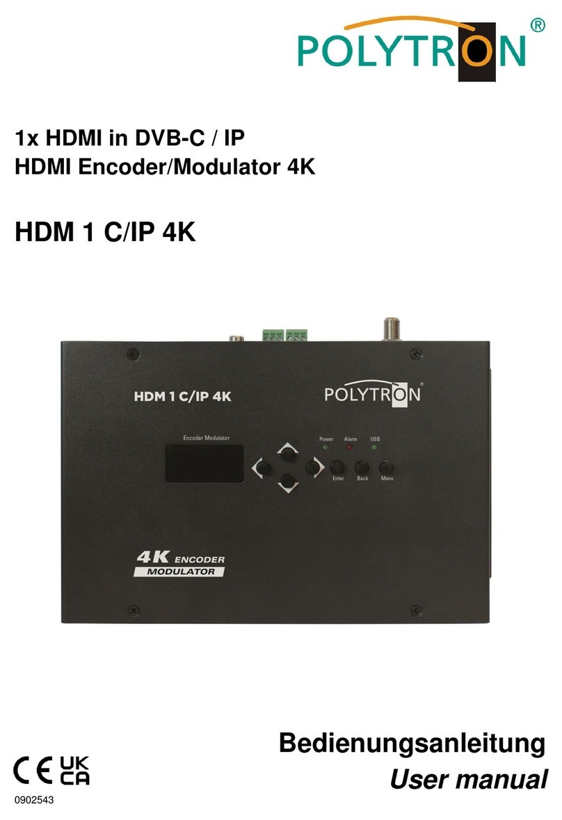
Polytron HDM 1 C/IP 4K User manual

Polytron

Polytron HDM 1 C/IP 4K User manual

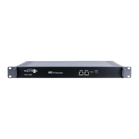
Polytron HDI 2 SDI User manual

Polytron

Polytron HDI 2 SDI User manual

Polytron HDI 32 C User manual

Polytron

Polytron HDI 32 C User manual

Polytron SPM-PSTI User manual

Polytron

Polytron SPM-PSTI User manual

Popular Media Converter manuals by other brands

Ewent EW1015 user manual

Ewent

Ewent EW1015 user manual

Ambery AV-3 Operation manual

Ambery

Ambery AV-3 Operation manual

Panasonic WJ-GXE100 Specifications

Panasonic

Panasonic WJ-GXE100 Specifications

DirectOut Technologies MADI.9648 user manual

DirectOut Technologies

DirectOut Technologies MADI.9648 user manual

Lenz Digital plus LF101XF manual

Lenz

Lenz Digital plus LF101XF manual

Crestron DM-NVX-E760 product manual

Crestron

Crestron DM-NVX-E760 product manual

Teradek T-RAX user guide

Teradek

Teradek T-RAX user guide

ATEN SXP-500 user manual

ATEN

ATEN SXP-500 user manual

GSS STC 100 Assembly instruction

GSS

GSS STC 100 Assembly instruction

Plextor Convertx PX-M402U Installation and user manual

Plextor

Plextor Convertx PX-M402U Installation and user manual

Clarion DVH940 owner's manual

Clarion

Clarion DVH940 owner's manual

Vitec Multimedia MGW user manual

Vitec Multimedia

Vitec Multimedia MGW user manual

Transition Networks C/T1E1-CF-01 user guide

Transition Networks

Transition Networks C/T1E1-CF-01 user guide

AJA HA5-12G Installation and operation guide

AJA

AJA HA5-12G Installation and operation guide

TR-Electronic LMRI-46-204 SSI manual

TR-Electronic

TR-Electronic LMRI-46-204 SSI manual

Bang & Olufsen BeoSound 5 user guide

Bang & Olufsen

Bang & Olufsen BeoSound 5 user guide

Pepperl+Fuchs EVS58-PZ manual

Pepperl+Fuchs

Pepperl+Fuchs EVS58-PZ manual

Transition Networks E-100BTX-FX-05(LC) user guide

Transition Networks

Transition Networks E-100BTX-FX-05(LC) user guide

manuals.online logo
manuals.online logoBrands
  • About & Mission
  • Contact us
  • Privacy Policy
  • Terms and Conditions

Copyright 2025 Manuals.Online. All Rights Reserved.