PONNDORF P delta Series User manual

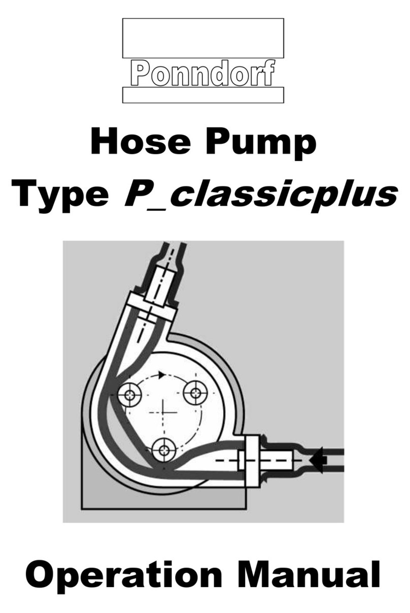
Hose Pump
Series
P_delta / PD-S
Operation Manual


PONNDORF Gerätetechnik GmbH
Leipziger Strasse 374
D - 34123 Kassel
Operation Manual
Hose Pump Series
P_delta / PD-S
Page 1 of 29
Version 003_GB / 04.2021
1. Content
2. General............................................................................................................................3
2.1 Service address................................................................................................................3
2.2 General information..........................................................................................................3
2.3 Labelling...........................................................................................................................4
2.4 Guarantee ........................................................................................................................5
2.5 Technical data..................................................................................................................5
3. Safety...............................................................................................................................6
3.1 Marking of details in the operation manual.......................................................................6
3.2 Safety instructions for hose pumps in hazardous locations...............................................7
3.3 Intended use.....................................................................................................................7
3.4 Qualification and training of personnel..............................................................................8
3.5 Dangers in case of non-observance of the safety instructions ..........................................8
3.6 Safety-conscious working.................................................................................................9
3.7 Safety instructions for the operator/user ...........................................................................9
3.8 Safety instructions for maintenance / inspection / assembly .............................................9
3.9 Unauthorized modifications or use of unoriginal parts.....................................................10
3.10 Unauthorized operating methods....................................................................................10
4. Transport, storage and disposal .................................................................................11
4.1 Transport........................................................................................................................11
4.2 Storage...........................................................................................................................11
4.3Disposal..........................................................................................................................11
5. Description of pump and accessories ........................................................................12
5.1 Detector for hose leakages.............................................................................................13
5.2 Diagram of the leakage detector for operating the pumps in non-hazardous locations (art.-
no. 93-000-055)..............................................................................................................14
5.3 Diagram of the leakage detector for operating the pumps in non-hazardous locations (art.-
no. 93-000-009)..............................................................................................................15
6. Installation / Connection / Operation...........................................................................16
6.1 Installation of pumps in hazardous locations...................................................................16
6.2 Electrical connection.......................................................................................................16
6.3 Mechanical connection...................................................................................................18
6.4 Installing the pump hose.................................................................................................20

PONNDORF Gerätetechnik GmbH
Leipziger Strasse 374
D - 34123 Kassel
Operation Manual
Hose Pump Series
P_delta / PD-S
Page 2 of 29
Version 003_GB / 04.2021
7. Maintencance / Service ................................................................................................22
7.1 Changing the pump hose................................................................................................22
7.2 Maintenance / Service....................................................................................................23
7.3 Cleaning.........................................................................................................................23
7.4 Adjustment of gap...........................................................................................................24
7.5 Drawing of spare parts –flanged version........................................................................25
7.6 List of spare parts –flanged version...............................................................................25
7.7 Drawing of spare parts –coupled version.......................................................................26
7.8 List of spare parts –coupled version ..............................................................................26
7.9 Troubleshooting..............................................................................................................27
8. Characteristic curves...................................................................................................28
9. Accompanying documents..........................................................................................29

PONNDORF Gerätetechnik GmbH
Leipziger Strasse 374
D - 34123 Kassel
Operation Manual
Hose Pump Series
P_delta / PD-S
Page 3 of 29
Version 003_GB / 04.2021
2. General
2.1 Service address
PONNDORF GERÄTETECHNIK GmbH
Leipziger Strasse 374
D - 34123 Kassel
Tel. 0561 / 51139 - 0
Fax: 0561 / 51139 - 88
2.2 General information
Ponndorf Hose Pumps are a self-priming positive displacement pumps without any glands
or valves. The pumping medium only comes in contact the inner surface of the pump hose,
but not with the moving parts of the pump. Therefore the pumps are particularly suitable for
pumping aggressive, abrasive and viscous liquids, but as well for pumping liquids
containing coarse-grained solids and sensitive materials which require to be pumped
gently.
Priming and pumping of combustible gases or fumes is prohibited.
Start-up and shutdown processes which require this should only be rarely
and kept as short as possible. Dry running of the pump (operation without
the pumping media) must generally be avoided, apart from the start-up and
shutdown processes mentioned before.
The operator must ensure that the relevant safety regulations (e.g. TRGS
727) for the pumped medium are observed to avoid dangerous electrostatic
charging. Among other things, please consider flow velocities, etc.
Hose pumps are only intended to pump free-flowing liquids but not to pump
gaseous pumping media.
The functioning of a hose pump can lead to abrasion on the pump hose. For
applications in which the possible abrasion is intermittent or not permissible,
appropriate filter technology must be provided by the customer.
To guarantee the tightness and chemical compatibility of the pump hoses,
the manufacturer of the hose pump must be consulted in case of possible
changes of the pumping media unless this information does not appear from
available documents.

PONNDORF Gerätetechnik GmbH
Leipziger Strasse 374
D - 34123 Kassel
Operation Manual
Hose Pump Series
P_delta / PD-S
Page 4 of 29
Version 003_GB / 04.2021
To avoid blockages of the pumps and/or any other damages of pumps or
pump hoses, the operator must guarantee that no hose damaging objects
can invade the hoses (e.g. sharp-edged or too big and not pumpable
objects). A suitable strainer may be used as protection.
2.3 Labelling
1. Pump Type 1)
2. Maximum Pressure
3. Pump Number and Year of Manufacture
4. ATEX Coding (optional)
5. Ambient Temperature Limit in EX-Zone (optional)
6. Customer Number –Order Number Ponndorf
1) Explanations of pump type: PD-S corresponds to series P_delta
Examples:
- PD3_15-S = P_delta 15, 3-rollers-rotor
- PD4_19-S = P_delta 19, 4-rollers-rotor
The data specified on the name plate refer to the delivery status of the Ponndorf Hose
Pump. Any modification of the pump can result in a change of the specified data and the
request of a new name plate for the Ponndorf Hose Pump could be necessary.
When requesting spares, the model and serial number should always be quoted.
1
6
5
4
3
2

PONNDORF Gerätetechnik GmbH
Leipziger Strasse 374
D - 34123 Kassel
Operation Manual
Hose Pump Series
P_delta / PD-S
Page 5 of 29
Version 003_GB / 04.2021
2.4 Guarantee
The guarantee for defects of any goods delivered by us is stated in our Terms and
Conditions of Sale.
We do not assume any liability for defects and damages which are caused by non-
observance of the instructions of the operation manual.
Furthermore we assume no liability for defects or damages which are caused by changing
the operating conditions (use not in accordance with the intended use), e.g. use of a
different pumping medium for which the pump hose is not suitable for, higher temperature
which exceed the maximum permissible or line losses caused by media with a too high
viscosity.
2.5 Technical data
Series
P_delta / PD-S
Size
15
19
Max. flow rate:
[l/h H2O]
500
975
Max. speed:
[n/min]
168
250
Max. pressure:
[bar]
4
2
Max. suction
height:
[m]
7
7
Max. viscositiy of
pumping media:
[mPas]
35.000
35.000
Max. motor
power:
[kW]
0,37
0,37
Weight:
execution XXX
execution GMC
execution GMF
[kg]
10 kg
25 kg
ca. 10 kg
ca. 25 kg
Hose material
Natural rubber
Ponnprene F

PONNDORF Gerätetechnik GmbH
Leipziger Strasse 374
D - 34123 Kassel
Operation Manual
Hose Pump Series
P_delta / PD-S
Page 6 of 29
Version 003_GB / 04.2021
3. Safety
These instructions contain basic recommendations that should be followed during
installation, operation and maintenance. Therefore the operation manual has to be read by
the fitter and qualified personnel/operator before installation and operation and must always
be available at the location of the machine/facility.
Not only the general instructions of safety mentioned in chapter - Safety - have to be
observed. The more specific safety instructions mentioned in other chapters must be
observed, too.
3.1 Marking of details in the operation manual
Non-observance of the safety instructions of this operation manual can endanger people.
Those instructions are particularly marked with the following general danger signs:
Safety sign according to DIN 4844 - W 9
Safety sign according to DIN 4844 - W 8
when warning of electrical hazards
Product-specific properties for explosion protection according to
2014/34 / EU are marked with the label in the operating instructions, e.g.
the intended use, temperatures.
The symbol is used in the operating instructions to mark safety-related
information relating to Directive 1999/92 / EC (ATEX operating directive)
that must be observed when operating the pumps, e.g. maintenance
information.
In case of safety instructions which can cause dangers for the machine
or its performance the term CAUTION is interpolated.
Signs directly fixed to the machine, e.g.
• arrows which indicate the flow rotation
• signs for fluid connections
have to be observed and must be kept in a readable condition.
CAUTION

PONNDORF Gerätetechnik GmbH
Leipziger Strasse 374
D - 34123 Kassel
Operation Manual
Hose Pump Series
P_delta / PD-S
Page 7 of 29
Version 003_GB / 04.2021
3.2 Safety instructions for hose pumps in hazardous locations
•
Explosive gas mixture or dust concentration can cause serious or even
fatal injuries in conjunction with hot, voltaged, pressurized and moved
parts of the pump
•
•
Only qualified technical personnel is authorized to effect installation,
connection, operation as well as maintenance and repair works in
consideration of
- provided instructions
- danger signs and/or decal information
- every other provided instructions for the user
- the system-dependent regulations and requirements
-the currently valid regulations concerning explosion protection and
safety as well as rules for accident prevention
The pump in connection with the mobile base plate only fulfils the
ATEX directive (EC Directive 2014/34/EC) in a stationary condition.
In case of moving the pump the operator has to make sure that no
explosive environment exists!
3.3 Intended use
•
Ponndorf Hose Pumps are intended for use in commercial facilities and
are only permitted for use in accordance to the information of the
technical documentation and of the nameplate.
They comply to the currently valid standards and regulations and meet
the requirements of the European directive 2014/34/EC.
•
If a pump is coupled to a drive unit, the operating manual of the drive
and other provided components must be observed, too.

PONNDORF Gerätetechnik GmbH
Leipziger Strasse 374
D - 34123 Kassel
Operation Manual
Hose Pump Series
P_delta / PD-S
Page 8 of 29
Version 003_GB / 04.2021
Before placing the pump into operation the operator must make sure that
•
the pump and all other components were not damaged during the
carriage.
•
the information on the nameplate concerning equipment group and
category, zone, temperature class and explosion group accords with
the permissible use in the particular hazardous location.
•
the air temperature of the ambience of the pump is observed.
•
the maximum temperature of the pumping media is not exceeded.
• +60°C continuous operation
• +80°C short-time operation (operating time max. 1 h)
•
pump hose, clamping rings and connecting sockets are mounted
properly and the pump hose is greased sufficiently with Ponndorf
special grease (as described in chapter 6.4).
In case of any discrepancies the pump must not be placed into operation!
While placing the pump into operation the characteristics (pump speed, pressure) which are
prescribed in the manual and on the nameplate must not be exceeded.
3.4 Qualification and training of personnel
The technical personnel responsible for operation, maintenance, inspection and installation
must be qualified for this work. Fields of responsibility, competencies and the supervision of
the personnel have to be exactly regulated by the operator. If the personnel is inadequately
skilled it must be trained and instructed. If necessary, this may be effected by order of the
operator by the manufacturer/supplier.
Furthermore the operator has to make sure that the personnel did absolutely catch the
contents of the operation manual.
3.5 Dangers in case of non-observance of the safety instructions
Non-observance of the safety instructions can endanger people, environment and
equipment and can result in losing any claim for damages.

PONNDORF Gerätetechnik GmbH
Leipziger Strasse 374
D - 34123 Kassel
Operation Manual
Hose Pump Series
P_delta / PD-S
Page 9 of 29
Version 003_GB / 04.2021
In detail non-observance can for instance result in the following dangers:
•
failure of important functions of the machine/facility
•
failure of methods prescribed for maintenance
•
threat to people because of electrical, mechanical and chemical effects
•
danger to the environment because of leakage of hazardous substances
3.6 Safety-conscious working
The safety instructions of this manual, the existing national rules for accident prevention as
well as potential instructions of the operator for work, operation and safety have to be
observed.
3.7 Safety instructions for the operator/user
•
If hot or cold machine parts cause dangers, the operator is responsible
for a protection against contact.
•
The protection against contact of moving parts of machines in
operation (e.g. coupling) must not be removed.
•
Leakages of hazardous pumping media (e.g. explosive, toxic, hot)
have to be discharged in a way which guarantees that no gangers to
people and environment arise. Legal regulations have to be observed.
•
Dangers caused by electrical power have to be eliminated.
(Please see also regulations e.g. of the VDE (in Germany) or of the
local power supply companies.)
3.8 Safety instructions for maintenance / inspection / assembly
The operator has to make sure that all maintenance, inspection and installation works will
be effected by authorized and qualified technical personnel, which is familiar with the
contents of the operating manual.
Basically all works may only effected during shutdown periods. The proceeding to shutdown
the machine described in the operating manual must be strictly observed.
Pumps or aggregates which convey harmful media have to be cleaned.

PONNDORF Gerätetechnik GmbH
Leipziger Strasse 374
D - 34123 Kassel
Operation Manual
Hose Pump Series
P_delta / PD-S
Page 10 of 29
Version 003_GB / 04.2021
When works are finished all safety installations and protectors must immediately be refitted
or be put into operation.
The articles of chapter 6 (Installation / Connection / Operation) have to be observed before
reconnection.
3.9 Unauthorized modifications or use of unoriginal parts
Modifications of the machine are only permissible after prior consultation of the
manufacturer. Original spare parts and accessories authorized by the manufacturer serve
the safety. Use of other parts can repeal the liability for any consequences.
3.10 Unauthorized operating methods
The reliability of the supplied machine is only guaranteed in case of intended use in
accordance to chapter 2 - General - of the operating manual.
The limit values stated in the data sheet must not be exceeded in any way.

PONNDORF Gerätetechnik GmbH
Leipziger Strasse 374
D - 34123 Kassel
Operation Manual
Hose Pump Series
P_delta / PD-S
Page 11 of 29
Version 003_GB / 04.2021
Holes for lifting the pump
(resp. to fix the base plate of stationary pumps)
4. Transport, storage and disposal
4.1 Transport
•
When choosing lifting tools and separate lifting accessories the weight
of the pump must be took into consideration. The corresponding
accident prevention regulations have to be observed.
(In Germany: UVV "Lastaufnahmeeinrichtungen im Hebezeugbetrieb",
BG 9a)
4.2 Storage
The pump has to be protected against humidity when stored.
In case of longer standstill before placing the pump into operation do not
assemble the pump hose, during longer shutdown periods remove the
hose from the pump. Otherwise the hose could be warped by the constant
compression of the rollers!
4.3 Disposal
With prolonged use, pump parts can get contaminated by poisonous or
radioactive pumped liquids to such an extent that cleaning may be
insufficient.
Risk of poisoning and environmental damage by the pumped liquid!
CAUTION
CAUTION

PONNDORF Gerätetechnik GmbH
Leipziger Strasse 374
D - 34123 Kassel
Operation Manual
Hose Pump Series
P_delta / PD-S
Page 12 of 29
Version 003_GB / 04.2021
•Use suitable personal protective equipment when carrying out any work on
the pump.
•Prior to disposal of the pump:
- Remove and dispose grease in accordance with local regulations.
- Dispose any leaking pumped liquid in accordance with local
regulations.
- Neutralize residues of pumped liquid in the pump.
•Dispose of the pump unit and associated parts in accordance with statutory
regulations.
5. Description of pump and accessories
The pump is available with directly flanged or coupled drive and is mounted on a base
plate. Construction "XXX" means that the pump head is supplied with bare shaft extension
without base plate.
Execution
Description
- XXX
- pump head with bare shaft extension, without drive
-GMC
- pump with coupled gear motor horizontal
- pump with coupled gear motor vertical
-GMF
- pump with flanged gear motor horizontal
- pump with flanged gear motor vertical
(not available for use in hazardous locations)
P_delta / PD-S
Material pump casing:
Aluminum alloy
Material base plate:
Steel (standard)
Diameter of shaft:
Fit:
15 mm
H7/k6

PONNDORF Gerätetechnik GmbH
Leipziger Strasse 374
D - 34123 Kassel
Operation Manual
Hose Pump Series
P_delta / PD-S
Page 13 of 29
Version 003_GB / 04.2021
5.1 Detector for hose leakages
The hose leakage detector is for a continuous monitoring in order to avoid unnoticed hose
leakages.
Functional description
In case of a hose leakage the pump can be switched off and an alarm (horn/signal lamp)
can be activated. This is only possible when using a motor contactor.
Safe function is only guaranteed with electrically conductive fluids.
The following mentionned detectors for hose leakages are available:
Part no. 93-000-055
Detecor for hose leackages for operating the pumps in non-hazardous locations and for
electrically conductive media.
Part no. 93-000-045
Detector for hose leackages with PLC sensor for operating the pumps in non-hazardous
locations and for electrically conductive and non-conductive media.
Part no. 93-000-009
Detector for hose leackages for operating the pumps in hazardous locations and for
electrically conductive and non-conductive media.
If other sensors are used, the operator is responsible for checking their
suitability.
Rear view of pump head
Borehole for sensor of hose
leakage detector
CAUTION

PONNDORF Gerätetechnik GmbH
Leipziger Strasse 374
D - 34123 Kassel
Operation Manual
Hose Pump Series
P_delta / PD-S
Page 14 of 29
Version 003_GB / 04.2021
5.2 Diagram of the leakage detector for operating the pumps in non-hazardous
locations (art.-no. 93-000-055)
The following diagram is only valid for the leakage detector consisting of:
• sensor for leakage detector (make Ponndorf, standard)
• switch amplifier (make: Disibeint, type DNSA)
The connections must only be made by qualified and authorized
personnel!
The standard detector for hose leakages is not suitable for use in
hazardous locations and non-conductive media.
drive
pump
B2
=
Level control, type DNSA
B1
=
sensor
F1
=
fuse
F2
=
motor fuse
F3
=
motor overloads
H1
=
run light
H2
=
signal horn, signal lamp
K1
=
motor contactor
K2
=
flasher (0,5 sec.)
M
=
motor (pump drive)
S1
=
push button

PONNDORF Gerätetechnik GmbH
Leipziger Strasse 374
D - 34123 Kassel
Operation Manual
Hose Pump Series
P_delta / PD-S
Page 15 of 29
Version 003_GB / 04.2021
5.3 Diagram of the leakage detector for operating the pumps in non-hazardous
locations (art.-no. 93-000-009)
The following diagram is only valid for the leakage detector consisting of:
• capacitive proximity switch (make: Rechner)
• switch amplifier (make: Rechner)
The switch amplifier must not be used in hazardous locations.
It has to be strictly installed outside of these areas.
The connections must only be made by qualified and authorized
personnel!
A1 –switch amplifier type N-132/1-01
B1 –capazitive sensor (2-wire NAMUR)
F1 –control fuse
F2 –motor fuse
F3 –motor protection relais
H1 –control lamp-operation
H2 –signal horn, signal lamp
K1 –motor contactor
K2 –flasher relais 0,5 sec.
M–motor –pump drive
S 1 –double push button

PONNDORF Gerätetechnik GmbH
Leipziger Strasse 374
D - 34123 Kassel
Operation Manual
Hose Pump Series
P_delta / PD-S
Page 16 of 29
Version 003_GB / 04.2021
6. Installation / Connection / Operation
Installation
The installation of the pump depends on the pump type and can be made stationary or
movable (on wheels).
6.1 Installation of pumps in hazardous locations
•
When pumps have to be installed in hazardous locations the
instructions in chapter 3.2 must be strictly observed.
•
Ponndorf Hose Pumps of series P_delta for hazardous location use
(optional!) meet the construction requirements of equipment group II,
category 3G/2G. They are intended for use in zone 1.
•
Hose pumps for hazardous location use in construction “0”
(see chapter 5 - Description of pump and accessories -)1)
•
are in accordance with temperature class T4.
•
are intended for use at an ambient temperature between +2°C and
+40°C (permissible temperature of place of installation).
•
are suitable for pumping media with a maximum temperature of:
• +60°C in continuous operation
• +80°C in short-time operation (operating time max. 1 h)
•
fulfill the requirements for non-electrical devices of the type of
protection c - protection through safe construction (marking with Ex
h for non-electrical explosion protection) - according to EN 80079-
36 and EN 80079-37.
•
are allowed for the explosion group IIB.
1) The explosion protection for complete aggregates can diverge! The details of the
enclosed declaration of conformity are relevant!
6.2 Electrical connection
The connections must only be made by qualified and authorized
personnel!
The connections must be made according to the wiring diagram in the
terminal box.
For instructions to effect the electrical connection please see the attached
manual of the pump drive!

PONNDORF Gerätetechnik GmbH
Leipziger Strasse 374
D - 34123 Kassel
Operation Manual
Hose Pump Series
P_delta / PD-S
Page 17 of 29
Version 003_GB / 04.2021
The pump must be protected by fuses and a protective motor switch
according to the nominal current of the motor.
The pumps must be integrated in the equipotential bonding of the whole
plant. For example this can be made by grounding the base frame by using
the grounding terminal in the terminal box of the motor.

PONNDORF Gerätetechnik GmbH
Leipziger Strasse 374
D - 34123 Kassel
Operation Manual
Hose Pump Series
P_delta / PD-S
Page 18 of 29
Version 003_GB / 04.2021
6.3 Mechanical connection
The nominal width of the tubing at the suction and the discharge side
should be approx. 25 % bigger than the nominal width of the pump hose.
The size of the hose pump is concurrent to the width of the pump hose.
The tubing on the suction side must be vacuum proof (reinforced) and the tubing on the discharge
side must withstand the maximum pressure of the pump. By using a pole changing switch the tubing
on suction and discharge side must withstand the maximum pressure of the pump.
Always use flexible tubing to connect
the pump with the pipework of your application.
The length of the tubing should be
at least 1 m. (see fig. 6.3.1).
The standard way of connection is flexible tubing (fitting the connecting sockets of the
pump), fixed with hose band clamps. Other options (e.g. threaded connections, Kamlok
couplings, standard flanges) are available on request.
In order to avoid pressure peaks, which can cause damages of the pump hose, there
should no pipe bends or 90° elbows be installed directly after the pump on the discharge
side (please see fig. 6.3.2 and 6.3.3).
Furthermore the cross section of the pipework on the discharge side should not be reduced
(please see fig. 6.3.4).
CORRECT
Fig. 6.3.1
WRONG
WRONG
WRONG
Fig. 6.3.3
Fig. 6.3.2
Fig. 6.3.4
This manual suits for next models
6
Table of contents
Other PONNDORF Water Pump manuals
Popular Water Pump manuals by other brands
Wilo
Wilo WILO-SCP Installation and operating instructions

DÖRR
DÖRR EcoPump HP Operation manual

Pentair
Pentair VERSAILLES 160/8 instruction manual

Dual Pumps
Dual Pumps WBU8200P manual
TET
TET Natural Reliability XTP Series instruction manual
GORMAN-RUPP
GORMAN-RUPP PA Series Installation, operation and maintenance manual


