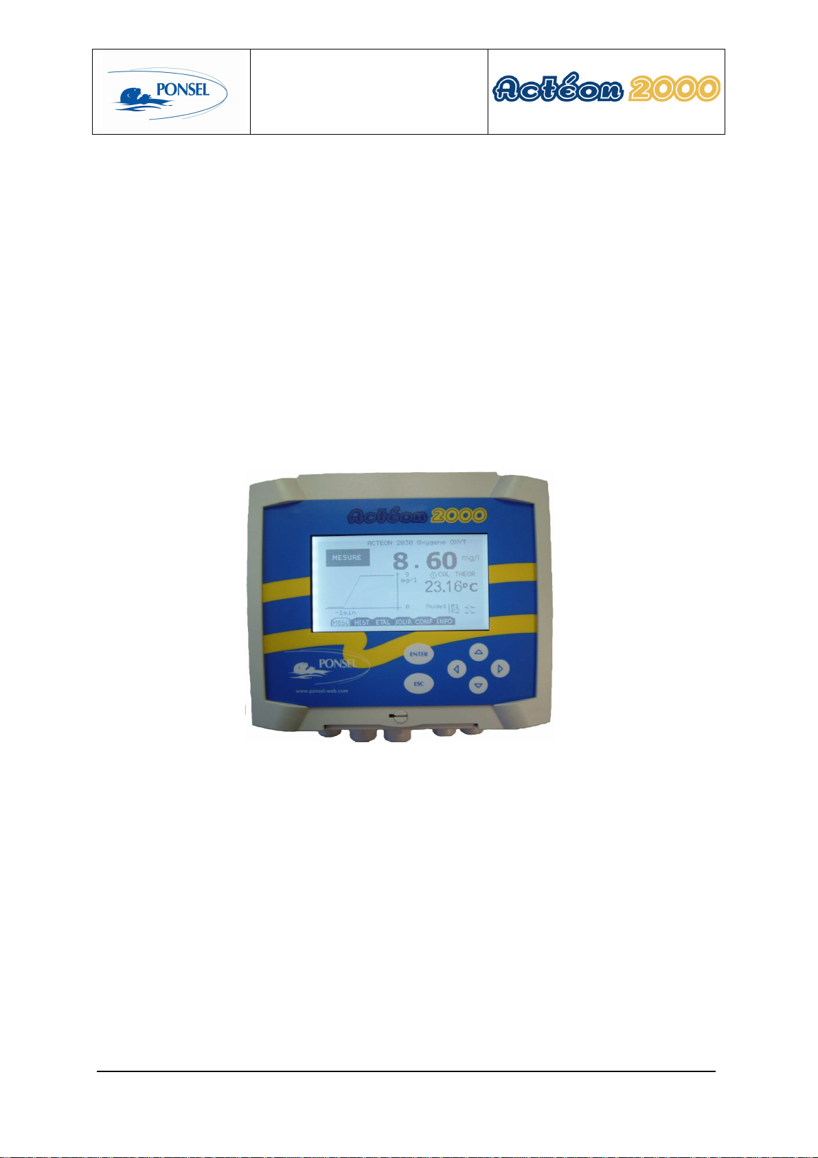
Ponsel ACTEON 2000 Series User manual

User manual
PONSEL Ref.: NOTICE_ACTEON_2030_v002.doc V : 002 1/65
ACTEON 2030
DO-Temperature
User manual

User manual
PONSEL Ref.: NOTICE_ACTEON_2030_v002.doc V : 002 2/65
IMPORTANT
Please read the manual carefully before
switching on the device.
In order to maintain and ensure the good working order of the device, users must comply with
the safety precautions and warnings featured in this manual.
Assembly and activation:
- Assembly, electrical connection, activation, operation and maintenance of the
measuring system must only be carried out by trained personnel duly authorised by the
end-user.
- Trained personnel must be familiar with and comply with the instructions in this
activation manual.
- Make sure the power supply complies with the specifications on the nameplate before
connecting the device.
- A clearly labelled power switch must be positioned near the device.
- Check all connections before turning the power on.
- Do not use damaged equipment: it may represent a hazard and should be labelled as
faulty.
- Repairs must only be carried out by the manufacturer or by a Ponsel after-sales-
service.

User manual
PONSEL Ref.: NOTICE_ACTEON_2030_v002.doc V : 002 3/65
CONTENTS
1THE MEASURING SYSTEM................................................................................6
1.1
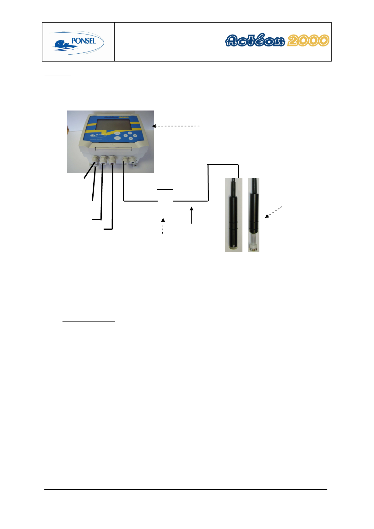
The basic system ..................................................................................................................................... 6
1.1.1
An O
2
and Temperature transmitter:.................................................................................................... 6
1.1.2
DO sensor............................................................................................................................................. 6
1.2
Accessories: ............................................................................................................................................. 7
1.2.1
Consumables........................................................................................................................................ 7
1.2.2
Accessories for a tank-mounted installation without cleaning system................................................. 7
1.2.3
Accessories for a tank-mounted installation with cleaning system...................................................... 7
1.2.4
Accessories for DO and temperature sensor in-pipe installation (PONCPC-O2T-P-10 or PONCPC-
OXYT-P-10)....................................................................................................................................................... 8
2INSTALLATION ...................................................................................................9
2.1
Mounting the ACTEON transmitter box.............................................................................................. 9
2.2
Connecting the ACTEON 2030 transmitter and DO sensor............................................................... 9
2.2.1
Acteon 2030 wiring:........................................................................................................................... 10
2.3
Tank-mounting:.................................................................................................................................... 10
2.3.1
Using the stand and protective hood.................................................................................................. 10
2.3.2
Installing the sensor with a sensor-holder perch (elbowed or straight) and nozzle (ref.: PONPPCC-O
or PONPPCD-O)............................................................................................................................................. 11
2.3.3
Installing an Elbowed Sensor-Holder Perch (ref: PONPPCC-CIR) or Straight Sensor-Holder Perch
(ref: PONPPCD-CIR) on QRPM (ref: PONSPFR and PONSPFR2)............................................................ 14
2.3.4
Installing a DO sensor cleaning system ............................................................................................. 15
2.4
In-pipe installation:............................................................................................................................... 16
3ACTEON 2010 TRANSMITTER.........................................................................17
3.1
Control console:.................................................................................................................................... 17
4BLOCK DIAGRAM OF ACTEON 2030 MENUS:...............................................18
5THE MEASUREMENT WINDOW.......................................................................19
6CALIBRATING THE ACTEON 2030..................................................................20
6.1
Calibrating the sensors:........................................................................................................................ 20
6.1.1
Two point DO sensor calibration (complete calibration):.................................................................. 21
6.1.2
DO sensor slope adjustment:.............................................................................................................. 24
6.1.3
Returning to measurement theoretical calibration: ............................................................................ 26
6.1.4
Two point temperature sensor calibration (complete calibration):..................................................... 27
6.1.5
Adjusting the temperature sensor slope: ............................................................................................ 30
6.1.6
Returning to temperature measurement theoretical calibration:......................................................... 32
6.2
DO sensor calibration error message information............................................................................. 33
6.2.1
Clean water and sulphite calibration error ......................................................................................... 33
6.2.2
Calibration error during air exposure................................................................................................. 33
6.3
Temperature sensor calibration error message information............................................................ 33
6.3.1
0°C calibration error .......................................................................................................................... 33
6.3.2
Ambient water calibration error......................................................................................................... 34
7VIEWING MEASUREMENT HISTORY..............................................................35

User manual
PONSEL Ref.: NOTICE_ACTEON_2030_v002.doc V : 002 4/65
8VIEWING THE SENSOR CALIBRATION REPORT ..........................................36
9CONFIGURING ACTEON 2000.........................................................................37
9.1
Configuring sensor response averaging.............................................................................................. 38
9.2
Configuring the trend line.................................................................................................................... 39
9.3
Configuring the two 4-20mA outputs.................................................................................................. 40
9.3.1
Adjusting 4-20mA output stop thresholds ......................................................................................... 41
9.3.2
Calibrating 4-20mA outputs............................................................................................................... 43
9.4
Adjusting relay outputs........................................................................................................................ 45
9.4.1
Configuring relays in mode 1:............................................................................................................ 45
9.4.2
Configuring relays in mode 2:............................................................................................................ 46
9.4.3
Configuring relays in mode 3:............................................................................................................ 48
9.5
Adjusting measurement units:............................................................................................................. 50
9.6
Setting the language: ............................................................................................................................ 51
9.7
Resetting factory default values: ......................................................................................................... 52
10 INFORMATION MENU.......................................................................................53
11 ADJUSTING THE ACTEON 2000 DISPLAY CONTRAST ................................53
12 TECHNICAL SPECIFICATIONS:.......................................................................54
13 SENSORS..........................................................................................................55
13.1
DO Sensor.............................................................................................................................................. 55
13.1.1
Principle:............................................................................................................................................ 55
13.1.2
Specifications:.................................................................................................................................... 55
13.1.3
Maintenance:...................................................................................................................................... 57
13.2
Temperature sensor.............................................................................................................................. 61
13.2.1
Maintenance:...................................................................................................................................... 61
13.2.2
Mechanical diagram:.......................................................................................................................... 61
14 QUESTIONS & ANSWERS................................................................................62
14.1
Display screen troubleshooting:........................................................................................................... 62
14.2
DO measurement troubleshooting:..................................................................................................... 63
15 APPENDIX:........................................................................................................64

User manual
PONSEL Ref.: NOTICE_ACTEON_2030_v002.doc V : 002 5/65
Figures
Figure 1 - Transmitter mounting diagram............................................................................................................... 9
Figure 2 - Installing a measuring system ................................................................................................................ 9
Figure 3 - Installation with a connection box........................................................................................................ 10
Figure 4 – Transmitter mount and hood................................................................................................................ 11
Figure 5 – PVC Elbowed Sensor-Holder Perch.................................................................................................... 12
Figure 6- Cross section diagram of the sensor nozzle without cleaning system ................................................... 13
Figure 7 - Installing a perch on a QRPM with one or two sliders......................................................................... 14
Figure 8 - Installing the DO sensor in the nozzle with the cleaning system.......................................................... 15
Figure 9 - Installing a DO sensor in a pipe............................................................................................................ 16
Figure 10 – OXYT sensor..................................................................................................................................... 56
Figure 11 - O2T sensor ......................................................................................................................................... 57
Figure 12 - Changing the OXYT membranes and electrolyte............................................................................... 59
Figure 13 - Changing the O2T membranes and electrolyte .................................................................................. 60
Figure 14 – Resetting ACTEON 2000.................................................................................................................. 62
Figure 15 - Transmitter wiring terminal layout..................................................................................................... 64

User manual
PONSEL Ref.: NOTICE_ACTEON_2030_v002.doc V : 002 6/65
1 The measuring system
1.1 The basic system
A measuring system requires the following basic elements:
1.1.1 An O
2
and Temperature transmitter:
PONACTEON2030-O2T ACTEON 2030-O2T Oxygen meter and Thermometer
transmitter (for agitated water, fast 10-20s sensor)
PONACTEON2030-OXYT ACTEON 2030-OXYT Oxygen meter and Thermometer
transmitter (for standing water, fast 1 min sensor)
The O
2
-Temperature transmitter comes with 1 box of membranes (2 membranes), 1 bottle of sulphite, 1 bottle of
electrolyte and a set of instructions.
1.1.2 DO sensor
Four sensors are available for different applications:
PONCPC-O2T-10 Oxygen and temperature sensor with 10m cable
connection (for perch mounting). Use with a 25µm
membrane (O2MBA). Fast 10-20s sensor
PONCPC-O2T-P-10 Oxygen and temperature sensor with 10m cable
connection (for perch mounting). Use with a 25µm
membrane (O2MBA). Fast 10-20s sensor
PONCPC-OXYT-10 Oxygen and temperature sensor with 10m cable
connection (for perch mounting). Use with a 50µm
membrane (O2MBSA). Slow 1 min sensor
PONCPC-OXYT-P-10 Oxygen and temperature sensor with 10m cable
connection (for perch mounting). Use with a 50µm
membrane (O2MBSA). Slow 1 min sensor

User manual
PONSEL Ref.: NOTICE_ACTEON_2030_v002.doc V : 002 7/65
1.2 Accessories:
1.2.1 Consumables
PONMANU-2030
Additional ACTEON 2030-O2T and ACTEON 2030-OXYT
operating instructions
PONO2-EL
60ml bottle of electrolyte (dropper bottle)
PONO2-MBA-6
Box of 6 PONCPC-O2T-10 sensor membranes
PONO2-MBSA-6
Box of 6 PONCPC-OXYT-10 sensor membranes
PONO2-ZR
20g bottle of sodium sulphite
PONO2T-CREP
Flat stainless steel strainer for PON-O2T-10 sensor
PONOXYT-CREP
Flat stainless steel strainer for PON-OXYTS-10 sensor
PONO2T-CREP-BZ
Flat bronze strainer for PON-O2T-10 sensor (anti-biofouling)
PONOXYT-CREP-BZ
Flat bronze strainer for PON-OXYT-10 sensor (anti-
biofouling)
1.2.2 Accessories for a tank-mounted installation without cleaning system
PON-ACT-24V Optional 24VDC power supply
PONBJ-E-O2-TU-MES-
ETC Watertight IP68 connection box for connecting the sensor at
distances over 10 metres
PONCBMC-9 9-conductor coated cable for the Connection box/Acteon 2000
connection
PON-PDPCV-1 PVC stand and protective hood for one ACTEON transmitter
PON-PDPCV-2 PVC stand and protective hood for two ACTEON transmitters
PON-CASQ-1 PVC protective hood for one ACTEON transmitter
PON-CASQ-2 PVC protective hood for two ACTEON transmitters
PONPPCC-O Elbowed sensor-holder perch for O2T and OXYT sensors.
Supplied with a nozzle, glued connector and 90° elbow for
perch closure
PONPPCD-O Straight sensor-holder perch for O2T and OXYT sensors.
Supplied with a nozzle, glued connector and 90° elbow for
perch closure SPECIFIC APPLICATION
PONBUSE-O2 Nozzle for O2T/OXYT sensors (without cleaning system)
PONCOUDE 90° elbow for sensor-holder perch closure
PONSPFR2C Stainless steel ESHP or SSHP type mount for 2 perches -1 arm,
2 sliders
PONSPFR1C Stainless steel ESHP or SSHP type mount for 1 perch -1 arm, 1
slider
PONSPFR-COUL Additional slider for QRPM (Quick release perch mount)
systems
PON-FILPO 10m potential cable
1.2.3 Accessories for a tank-mounted installation with cleaning system
PONCA-HX1 Air compressor in IP65 casing for permanent cleaning, 230V
power supply (to be used with a perch and nozzle for cleaning)
PONPPCC-O-NET Elbowed sensor-holder perch for O2T and OXYT sensors.
Supplied with nozzle and tube for housing the cleaning system
and rilsan tube
PONBUSE-O-NET pps2 nozzle for O2TS and OXYT sensors (with cleaning
system)
PONTUBE-NET 4 x 6mm black rilsan tube for cleaning system, 7 metres long
complete with connector + 3 metres in the perch

User manual
PONSEL Ref.: NOTICE_ACTEON_2030_v002.doc V : 002 8/65
1.2.4 Accessories for DO and temperature sensor in-pipe installation (
PONCPC-O2T-
P-10 or PONCPC-OXYT-P-10
)
PON4020 Tee assembly fitted with 20 x 27 male/female sockets for AP1.
To be fitted on PVC piping
PON40 40 diameter glued tee assembly (without connectors) for AP1
PONAP1 Adapter sleeve for oxygen and temperature sensor in-pipe
installation
PONVCPO-63 Stainless steel 63mm clamp type assembly for in-pipe
installation (316 L) (for SS OXY, Eh, pH, Temp., C2E and
C4E sensors) To be fitted with the appropriate nipple. To be
fitted on stainless steel piping
PONNIP-O2T/OXYT O2T/OXYT sensor nipple

User manual
PONSEL Ref.: NOTICE_ACTEON_2030_v002.doc V : 002 9/65
2 Installation
2.1 Mounting the ACTEON transmitter box
Acteon 2030 mounting diagram
A B C
Dimensions (mm) 156.5 181 195.3
Figure 1 - Transmitter mounting diagram
2.2 Connecting the ACTEON 2030 transmitter and DO sensor
Figure 2 - Installing a measuring system
DO/Temperature sensor
PONCPC-OXYT-10 or
PONCPC-O2T-10
Relay
4-20mA
output 10 metres max.
~230V
~230V line out
cable
Potential cable for earth
connection
ACTEON 2030 DO and Temperature
Transmitter

User manual
PONSEL Ref.: NOTICE_ACTEON_2030_v002.doc V : 002 10/65
Comment:
If the connection cable between the sensor and transmitter is longer than 10 metres, a watertight IP 68
connection box must be used (REF: PON-BJ-E).
Figure 3 - Installation with a connection box
2.2.1 Acteon 2030 wiring
See appendix (§15) at the end of the document.
2.3 Tank-mounting:
2.3.1 Using the stand and protective hood
A protective hood (PON-PDPVC-1) is available for mounting the ACTEON 2000.
The hood is essential in the case of direct exposure to adverse weather or sunshine.
ACTEON 2030 DO and
Temperature Transmi
tter
~230V
Relays
4-20mA
output
10
metres max.
Connection box
(PON-BJ-E)
~230V earth
wire or line out
cable
DO/Temperature sensor
PONCPC-OXYT-10 or
PONCPC-O2T-10

User manual
PONSEL Ref.: NOTICE_ACTEON_2030_v002.doc V : 002 11/65
Figure 4 – Transmitter mount and hood
2.3.2 Installing the sensor with a sensor-holder perch (elbowed or straight) and
nozzle (ref.: PONPPCC-O or PONPPCD-O)
It is best to use the elbowed sensor-holder perch when immersing the sensor in a tank.

User manual
PONSEL Ref.: NOTICE_ACTEON_2030_v002.doc V : 002 12/65
Figure 5 – PVC Elbowed Sensor-Holder Perch
Comment:
Use elbowed sensor-holder perches in heavily soiled tanks to prevent fibre build-up on the perch.
Installing the O2 sensor in the nozzle:
1) Dismantle the sensor-holder perch then remove the nozzle from the bottom of the perch by removing its
tightening screw.
2) Introduce a solid wire into the perch then a string.
3) Remove the sensor's protective casing and two O-ring seals.
4) Attach the string to the end of the sensor and introduce it into the top of the perch. Use the string to pull
the sensor to the bottom of the perch.
5) Remove the string and place the sensor in the nozzle. The sensor should protrude about twenty
centimetres.
6) Replace only the O-ring seal nearest the low section of the sensor.
7) Adjust the tip of the sensor exactly flush with the end of the nozzle. Secure the sensor in place with the
tightening screw.
8) Replace the nozzle on the perch and secure it with the tightening screw.
Sensor in the nozzle
50cm
minimum
Flow direction of liquid
Sensor-holder perch
Glued connector
Sensor-holder nozzle
Lock-nut
Liquid level
45°
2m2055cm

User manual
PONSEL Ref.: NOTICE_ACTEON_2030_v002.doc V : 002 13/65
9) Use the stand with a slider or another sort of system to set the perch in a vertical position. Adjust the
immersion parameters so that the nozzle always remains submerged and the submerged section is
always at least 0.50cm below the surface.
10) To prevent fibre build-up, position the sensor so that the nozzle is facing in the same direction as the
flow.
Diagram of the sensor in the nozzle without cleaning system
Figure 6- Cross section diagram of the sensor nozzle without cleaning system
Comment: The line out cable is to be connected to the ACTEON 2030 earth terminal.
O2 SENSOR (
PONCPC
-
OXYT
-
10)
Tightening screw
Perch
O2 SENSOR (
PONCPC
-
O2T
-
10)
Ti
ghtening screw
Tightening
screw

User manual
PONSEL Ref.: NOTICE_ACTEON_2030_v002.doc V : 002 14/65
2.3.3 Installing an Elbowed Sensor-Holder Perch (ref: PONPPCC-CIR) or Straight
Sensor-Holder Perch (ref: PONPPCD-CIR) on QRPM (ref: PONSPFR and
PONSPFR2)
1) Fix the stainless steel QRPM to the infrastructure.
2) Next, fix a sensor-holder perch to the stainless steel QRPM as shown in the diagram below.
Figure 7 - Installing a perch on a QRPM with one or two sliders
A second slider may be added to install a second sensor-holder perch for the temperature sensor (see diagram
above).

User manual
PONSEL Ref.: NOTICE_ACTEON_2030_v002.doc V : 002 15/65
2.3.4 Installing a DO sensor cleaning system
To lengthen the time between each clean, use the compressed air cleaning system (PONCA-HXI).
1) Dismantle the sensor-holder perch then remove the nozzle from the bottom of the perch by removing its
tightening screw.
2) Introduce a solid wire into the perch then a string.
3) Remove the sensor's protective casing and two O-ring seals.
4) Attach the string to the end of the sensor and introduce it into the top of the perch. Use the string to pull
the sensor to the bottom of the perch.
5) Remove the string and place the sensor in the nozzle. The sensor should protrude about twenty
centimetres.
6) Replace only the O-ring seal nearest the low section of the sensor.
7) Adjust the tip of the sensor exactly flush with the end of the nozzle. Secure the sensor in place with the
tightening screw.
8) Replace the nozzle on the perch and secure it with the tightening screw.
9) Use the stand with a slider or another sort of system to set the perch in a vertical position. Adjust the
immersion parameters so that the nozzle always remains submerged and the submerged section is
always at least 0.50cm below the surface.
10) To prevent fibre build-up, position the sensor so that the nozzle is facing in the same direction as the
flow.
Figure 8 - Installing the DO sensor in the nozzle with the cleaning system
Vis de serrage
PVC perch
Sensor
Nozzle
Screw (do not
overtighten)
Perch/nozzle screw
pay attention to alignment
Continuous air
cleaning
O-ring seal
Flexible material
1cm overhang

User manual
PONSEL Ref.: NOTICE_ACTEON_2030_v002.doc V : 002 16/65
2.4 In-pipe installation:
For in-pipe installations, use the tee assembly (PON-4020) and the adapter sleeve (PONAP1).
Figure 9 - Installing a DO sensor in a pipe
20x27 connectors
DO sensor (PONCPC-
O2T-P-10 or PONCPC-
OXYT-P-10)
Sleeve (PONAP1)
Tee (PON4020)

User manual
PONSEL Ref.: NOTICE_ACTEON_2030_v002.doc V : 002 17/65
3 ACTEON 2030 transmitter
3.1 Control console:
1
1
ENTER key for accessing menus or confirming actions
2
ESC key for exiting menus or cancell
ing actions
3
for moving left in menus
4
5
for moving right in menus
for increasing a value or selecting the menu above
6
decreasing a value or selecting the menu below
8
Quarter
-
turn screw to seal cover
2
5 3
4 6
8
7
7
Control screen

User manual
PONSEL Ref.: NOTICE_ACTEON_2030_v002.doc V : 002 18/65
4 Block diagram of ACTEON 2030 menus:
MEASURE
CONFIGURATION
Language configuration (§9.6)
4-20mA output
adjustment
Relay adjustment
CALIBRATION
Adjusting the graphic screen (§9.2)
Measure unit configuration (§9.5)
GENERAL
INFORMATION
HISTORY
CALIBRATION
LOGGER
Config. of 4mA and 20mA
stop switches (§
9.3.1
)
4-20mA output calibration
(§9.3.2)
Threshold adjustment in
mode 1 (§
9.4.1
)
Threshold adjustment in
mode 2 (§
9.4.2
)
Factory default
configuration
reminder
(§
9.7
)
Gain adjust (§6.1.2)
Complete calibration (§
6.1.1
)
Theoretical calibration (§
6.1.3
)
Gain adjust (§6.1.5)
Complete calibration (§6.1.4)
Theoretical calibration (§ 6.1.6)
Oxygen sensor
Temperature sensor
Threshold adjustment in
mode 3 (§)

User manual
PONSEL Ref.: NOTICE_ACTEON_2030_v002.doc V : 002 19/65
5 The measurement window
In measure mode the measurement screen displays various types of information :
20.00
°C
-
24
hrs
4.31
MEASURE
mg/l
INFO
CONF
HIST
CAL
LOG
MEAS
R1
R2
!
CAL
ACTEON
2030 DO
-
OXYT
mg/l
6
8
1
2
3
4
5
1
Dissolved oxygen measurement in mg/l or % of saturation
2
Measurement state indicator:
THEOR CAL
: Indicates use of the theoretical coefficients as calibration
coefficients.
!
!
CAL
: Indicates incorrect calibration point on the probe.
6
4
R1 and R2 relays: state and operating
mode
ACTEON menu
5
6
Trend line can be configu
red from 1
min to 24
hours (with automatic scaling)
Temperature transmitted by the temperature sensor
In the event of faulty wiring or uninstalled sensor, the temperature will not be displayed and
temperature compensation will be set to 25°C
Comment: The following icon is displayed if the temperature is higher than the operating
temperature (55°C)
3
: No icon displayed means that the last calibration is correct.
Contact is inactive.
Contact is active.
Mode1
HOT
!

User manual
PONSEL Ref.: NOTICE_ACTEON_2030_v002.doc V : 002 20/65
6 Calibrating the ACTEON 2030
6.1 Calibrating the sensors:
Select the calibration menu in the measurement window:
20.00
°C
-
24
hrs
4.31
MEASURE
mg/l
INFO
CONF
HIST
CAL
LOG
MEAS
Mode1 R1
R2
ACTEON 2030 Oxygen meter OXYT
ml/l
6
8
Use the
and
keys to
navigate the ACTEON menu
CALIBRATION
SENSORS CALIBRATION
DO SENSOR
Gain adjust
Complete calibration
Theoretical calibration
TEMPERATURE SENSOR
Zero rectification
Complete calibration
Theoretical calibration
ENTER: Validate the choice
Select the CAL menu and press ENTER.
Other manuals for ACTEON 2000 Series
1
This manual suits for next models
1
Table of contents
Other Ponsel Measuring Instrument manuals