Ponsel ACTEON 2020 Redox-Temperature User manual

User manual
PONSEL Ref.: NOTICE_ACTEON_2020_v003 V : 003 1/57
ACTEON 2020
Redox-Temperature
User manual

User manual
PONSEL Ref.: NOTICE_ACTEON_2020_v003 V : 003 2/57
IMPORTANT
Read the manual carefully before switching the
device on.
In order to maintain and ensure the good working order of the device, users must comply with
the safety precautions and warnings featured in this manual.
Assembly and activation:
- Assembly, electrical connection, activation, operation and maintenance of the
measuring system must only be carried out by trained personnel duly authorised by the
end-user.
- Trained personnel must be familiar with and comply with the instructions in this
activation manual.
- Make sure the power supply complies with the specifications on the nameplate before
connecting the device.
- A clearly labelled power switch must be positioned near the device.
- Check all connections before turning the power on.
- Do not use damaged equipment: it may represent a hazard and should be labelled as
faulty.
- Repairs must only be carried out by the manufacturer or by a Ponsel after-sales
service.

User manual
PONSEL Ref.: NOTICE_ACTEON_2020_v003 V : 003 3/57
CONTENTS
1THE MEASURING SYSTEM..................................................................................6
1.1
The basic system ........................................................................................................................................6
1.1.1
A Redox-Temperature transmitter ..........................................................................................................6
1.1.2
A Redox sensor.......................................................................................................................................6
1.1.3
A temperature sensor ..............................................................................................................................6
1.2
Accessories..................................................................................................................................................7
1.2.1
Accessories for a tank-mounted installation without cleaning system....................................................7
1.2.2
Accessories for Redox (PONCPC-EH-10) and Temperature (PONCPC-T-10) sensor in-pipe
installation..............................................................................................................................................................7
1.2.3
Accessories for Redox filling sensors (PONCPC-PH-RV-10)..............................................................7
1.2.4
Consumables...........................................................................................................................................7
1.2.5
Sensor connector adapter........................................................................................................................8
2INSTALLATION .....................................................................................................9
2.1
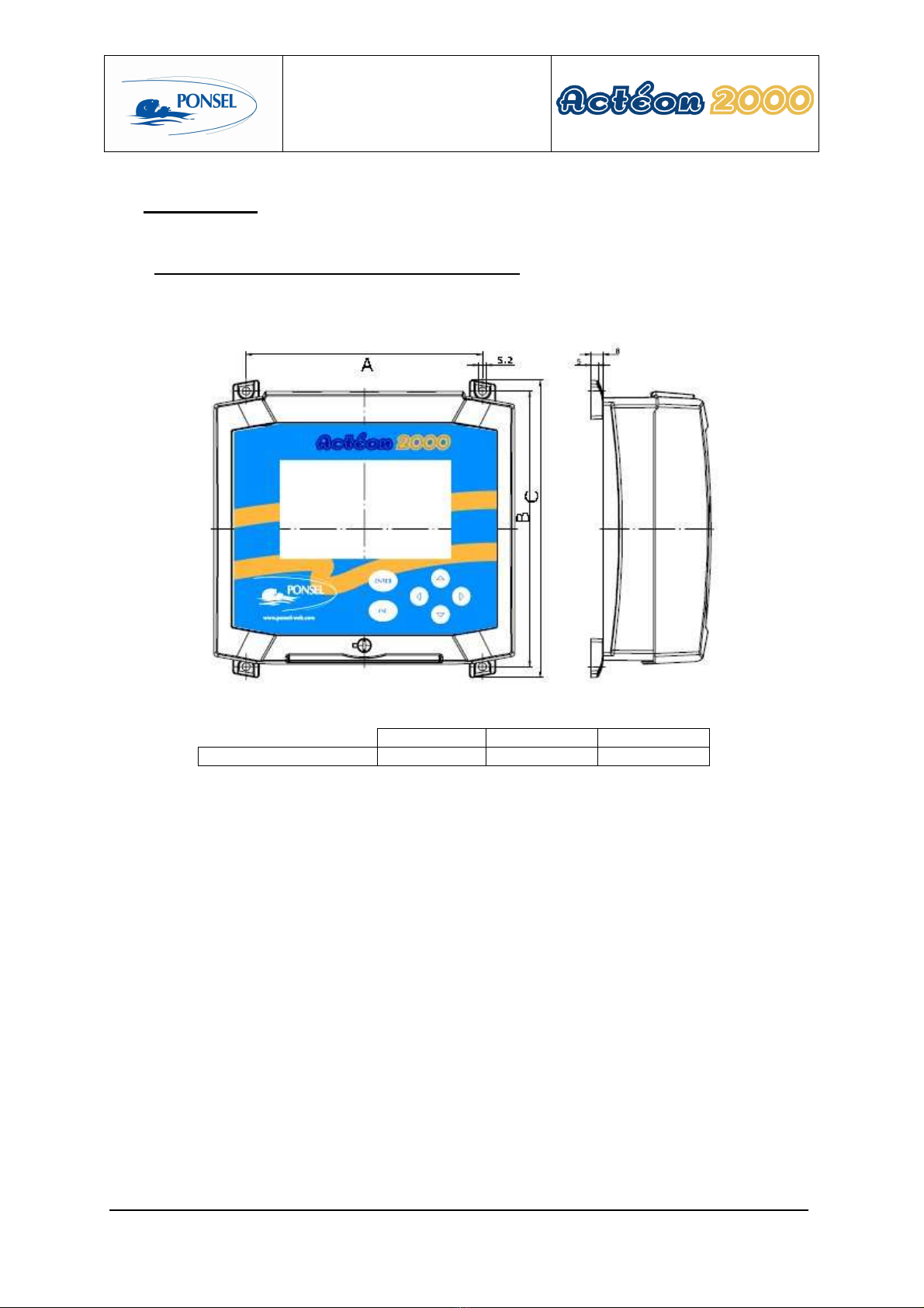
Mounting the ACTEON 2020 transmitter box........................................................................................9
2.2
Connecting the ACTEON 2020 transmitter and Redox and Temperature sensors...........................10
2.2.1
Acteon 2020 wiring...............................................................................................................................11
2.3
Tank-mounting ........................................................................................................................................12
2.3.1
Using the stand and protective hood.....................................................................................................12
2.3.2
Installing the sensor with a sensor-holder perch (elbowed or straight) and nozzle (PONPPCC-
PH/EH or PONPPCD-PH/EH)..........................................................................................................................12
2.3.3
Installing an Elbowed Sensor-Holder Perch (ref: PONPPCC-CIR) or Straight Sensor-Holder Perch
(ref: PONPPCD-CIR) on QRPM (ref: PONSPFR and PONSPFR2)...............................................................14
2.4
In-pipe installation:..................................................................................................................................15
3ACTEON 2020 TRANSMITTER...........................................................................16
3.1
Control console.........................................................................................................................................16
4BLOCK DIAGRAM OF ACTEON 2020 MENUS.................................................. 17
5THE MEASUREMENT WINDOW.........................................................................18
6CALIBRATING THE ACTEON 2020....................................................................19
6.1
Calibrating the sensors............................................................................................................................19
6.1.1
Two point Redox (ORP) sensor calibration (complete calibration):.....................................................20
6.1.2
Redox sensor slope adjustment.............................................................................................................23
6.1.3
Returning to REDOX measurement theoretical calibration:.................................................................25
6.1.4
Two point temperature sensor calibration (complete calibration).........................................................26
6.1.5
Temperature sensor slope adjustment...................................................................................................29
6.1.6
Returning to temperature measurement theoretical calibration.............................................................31
6.2
Redox sensor calibration error message................................................................................................32
6.2.1
Automatic zero measurement error.......................................................................................................32
6.2.2
240mV or 470mV buffer solution calibration error..............................................................................32
6.3
Temperature sensor calibration error message information...............................................................32
6.3.1
0°C calibration error .............................................................................................................................32
6.3.2
Ambient water calibration error............................................................................................................33

User manual
PONSEL Ref.: NOTICE_ACTEON_2020_v003 V : 003 4/57
7VIEWING MEASUREMENT HISTORY................................................................34
8VIEWING THE SENSOR CALIBRATION REPORT ............................................ 35
9CONFIGURING ACTEON 2020...........................................................................36
9.1
Configuring sensor response averaging.................................................................................................37
9.2
Configuring the trend line.......................................................................................................................38
9.3
Configuring the two 4-20mA outputs.....................................................................................................39
9.3.1
Adjusting 4-20mA output stop thresholds ............................................................................................40
9.3.2
Calibrating 4-20mA outputs..................................................................................................................42
9.4
Adjusting relay outputs...........................................................................................................................44
9.4.1
Configuring relays in mode 1................................................................................................................45
9.4.2
Configuring relays in mode 2:...............................................................................................................46
9.5
Adjusting measurement units.................................................................................................................47
9.6
Setting the language.................................................................................................................................48
9.7
Resetting factory default values..............................................................................................................49
10 INFORMATION MENU......................................................................................... 50
11 ADJUSTING THE ACTEON 2020 DISPLAY CONTRAST ..................................51
12 TECHNICAL SPECIFICATIONS:......................................................................... 51
13 SENSORS............................................................................................................ 52
13.1
REDOX (ORP) sensor.............................................................................................................................52
13.1.1
Specifications:.......................................................................................................................................52
13.1.2
Description............................................................................................................................................52
13.1.3
Activation..............................................................................................................................................53
13.1.4
Maintenance..........................................................................................................................................53
13.1.5
Cleaning................................................................................................................................................53
13.2
Temperature sensor.................................................................................................................................53
13.2.1
Maintenance..........................................................................................................................................53
13.2.2
Mechanical diagram..............................................................................................................................54
14 QUESTIONS & ANSWERS.................................................................................. 55
14.1
Display screen troubleshooting...............................................................................................................55
15 APPENDIX:.......................................................................................................... 56

User manual
PONSEL Ref.: NOTICE_ACTEON_2020_v003 V : 003 5/57
Figures
Figure 1 - Transmitter mounting diagram............................................................................................................... 9
Figure 2 - Installing a measuring system .............................................................................................................. 10
Figure 3 – Installation with a connection box with integrated pre-amplifier ........................................................ 11
Figure 4 - Mount and hood for the transmitter...................................................................................................... 12
Figure 5 – PVC Elbowed Sensor-Holder Perch.................................................................................................... 12
Figure 6- Cross section diagram of the sensor nozzle without cleaning system ................................................... 13
Figure 7 – Installing a perch on a QRPM with one or two sliders ........................................................................ 14
Figure 8 - Installing a temperature sensor inside a pipe........................................................................................ 15
Figure 9 - Installing a temperature sensor in a pipe .............................................................................................. 15
Figure 10 - Redox sensor diagram ........................................................................................................................ 52
Figure 11 - Resetting ACTEON 2020................................................................................................................... 55
Figure 12 - Transmitter wiring terminal layout..................................................................................................... 56

User manual
PONSEL Ref.: NOTICE_ACTEON_2020_v003 V : 003 6/57
1 The measuring system
1.1 The basic system
A measuring system requires the following basic elements:
1.1.1 A Redox-Temperature transmitter
PONACTEON2020-EH-T ACTEON 2020 Redox meter and thermometer
transmitter
The Redox-Temperature transmitter comes with a 240mV buffer solution and a user manual.
1.1.2 A Redox sensor
Three sensors are available for different applications:
PONCPC-EH-10 Plastogel electrolyte EH sensor (platinum tip) with 10m
cable connection (perch mounting or in-pipe installation)
PONCPC-EHAN-10 Plastogel electrolyte EH sensor (platinum ring) with 10
m cable connection (perch mounting or in-pipe
installation)
With very low conductivity (less than 50µS/cm) and contaminating media, iIt is recommended to use a filling
sensor for cold liquids.
PONCPC-EH-RV-10 Glass bodied Eh filling sensor with 10-metre cable
connection
1.1.3 A temperature sensor
PONCPC-T-10 Temperature sensor with 10m cable connection (perch-
mounting or in-pipe installation)

User manual
PONSEL Ref.: NOTICE_ACTEON_2020_v003 V : 003 7/57
1.2 Accessories
1.2.1 Accessories for a tank-mounted installation without cleaning system
PON-BJAI-E PH/EH/T Watertight IP 68 connection box with integrated pre-amplifier (supplied
with 10 metres of cable) for pH/Eh and temperature sensors connections
at distances over 10 metres (see Figure 3 – Installation with a connection
box with integrated pre-amplifier
)
PONCBMC-9 9-conductor coated cable for the Connection box/Acteon connection
PON-ACT-24V Optional 24VDC power supply
PON-PDPCV-1 PVC stand and protective hood for one ACTEON transmitter
PON-PDPCV-2 PVC stand and protective hood for two ACTEON transmitters
PON-CASQ-1 PVC protective hood for one ACTEON transmitter
PON-CASQ-2 PVC protective hood for two ACTEON transmitters
PONPPCC-PH/EH/T Elbowed sensor-holder perch (ESHP) for pH/Eh or Temperature sensors.
Supplied with nozzle and glued connector.
PONPPCD-PH/EH/T Straight sensor-holder perch for pH/Eh and Temperature sensors supplied
with nozzle and glued connector SPECIFIC APPLICATION
PONBUSE-PH/EH/T Nozzle for pH/Eh (without cleaning system) and Temperature sensors.
Complete with 50 diameter BP3P glued connector
PONCOUDE 90° elbow for sensor-holder perch closure
PONSPFR2C Stainless steel ESHP or SSHP type mount for 2 perches -1 arm, 2 sliders
PONSPFR1C Stainless steel ESHP or SSHP type mount for 1 perch -1 arm, 1 slider
PONSPFR-COUL Additional slider for QRPM (Quick release perch mount) systems
1.2.2 Accessories for Redox (
PONCPC-EH-10
) and Temperature (
PONCPC-T-10)
sensor
in-pipe installation
PON4020 Tee assembly fitted with 20 x 27 male/female sockets for AP1. To be
fitted on PVC piping.
PON40 40 diameter glued tee assembly (without connectors) for AP1
PONAP1 Adapter sleeve for pH and temperature sensor in-pipe installation
PONVCPO-63 Stainless steel 63mm clamp type assembly for in-pipe installation (316 L)
(for SS OXY, Eh, pH, Temp., C2E and C4E sensors) To be fitted with the
appropriate nipple. To be fitted on stainless steel piping.
PONNIP-PH/EH pH/Eh sensor nipple
PONNIP-PH/EH-T Nipple for 2 pH/T or Eh/T or pH/Eh sensors
PONNIP-T Temperature sensor nipple
1.2.3 Accessories for Redox filling sensors (
PONCPC-PH-RV-10)
PONRAC-EH-RV Connector for filling system
PONRES-EH-RV 5-litre capacity electrolyte tank for filling system
PONROB-EH-RV Electrolyte tank tap for filling systems
PONROB-EH-RV 10-metre tube for connecting the tank to the strainer and for filling
systems
PONCREP-EH-RV Filling system strainer
1.2.4 Consumables
PONMANU-2020-EH-T
Additional ACTEON 2020 user manual
PONKCL-1M
KCI (1M) for EH filling sensors
PONKCL-2M
KCI (2M) for EH filling sensors

User manual
PONSEL Ref.: NOTICE_ACTEON_2020_v003 V : 003 8/57
PONKCL-3M
KCI (3M) for EH filling sensors
PONPEPNET
125ml bottle of pepsin cleaning solution for Eh and pH sensors
PONSOLCSV
125ml bottle of storage solution for pH/Eh sensors
PONEHSOL240
Buffer solution for Redox meters: 240mV at 25°C, 125ml bottle
PONEHSOL470
Buffer solution for Redox meters: 470mV at 25°C, 125ml bottle
1.2.5 Sensor connector adapter
These adapters are used to connect Acteon 2000 units to PONSEL sensors with connectors.
PONADAP-EHAN ACTEON 2020 adapter for PONCPC-EHAN-S10 and PONCPC-EH-S10
sensors
PONADAP-T Adapter for PONCPC-T-S10 sensor

User manual
PONSEL Ref.: NOTICE_ACTEON_2020_v003 V : 003 9/57
2 Installation
2.1 Mounting the ACTEON 2020 transmitter box
ACTEON 2020 mounting diagram
A B C
Dimensions (mm) 156.5 181 195.3
Figure 1 - Transmitter mounting diagram

User manual
PONSEL Ref.: NOTICE_ACTEON_2020_v003 V : 003 10/57
2.2 Connecting the ACTEON 2020 transmitter and Redox and Temperature
sensors
•Distance Transmitter – sensors < 10 m
Figure 2 - Installing a measuring system
Relay cable (2 channels)
4-20mA cable (2 channels)
Power supply cable
(230V~ or 24VDC)
Line out cable
1
5
2
3
1
2
3 4
4
Redox (ORP) sensor
5
6
Temperature sensor
(PONCPC-T-10)
6

User manual
PONSEL Ref.: NOTICE_ACTEON_2020_v003 V : 003 11/57
•Distance Transmitter – Sensors > 10 m
If the connection cable between the pH sensor and transmitter is longer than 10 metres, a watertight IP 68
connection box with integrated pre-amplifier must be used (REF: PON-BJAI-E PH/EH/°C).
Figure 3 – Installation with a connection box with integrated pre-amplifier
2.2.1 Acteon 2020 wiring
See appendix (§15) at the end of the document.
Relay cable (2 channels)
4-20mA cable (2 channels)
Power supply cable
(230V~ or 24VDC)
Line out cable
1
5
2
3
1
2
3 4
4
Redox (ORP) sensor
5
6
Temperature sensor
6
7
7
Connection box
(PON-BJAI-E
PH/EH/T)

User manual
PONSEL Ref.: NOTICE_ACTEON_2020_v003 V : 003 12/57
2.3 Tank-mounting
2.3.1 Using the stand and protective hood
In the case of direct exposure to adverse weather or sunshine, a protective hood (PON-PDPVC-1) is essential.
Figure 4 - Mount and hood for the transmitter
2.3.2 Installing the sensor with a sensor-holder perch (elbowed or straight) and
nozzle (PONPPCC-PH/EH or PONPPCD-PH/EH)
Figure 5 – PVC Elbowed Sensor-Holder Perch
Sensor in the nozzle
50cm
minimum
Flow direction of liquid
Sensor-holder perch
Glued connector
Sensor-holder nozzle
Lock- nut
Liquid level
45°
2.20m55cm

User manual
PONSEL Ref.: NOTICE_ACTEON_2020_v003 V : 003 13/57
Comment:
Use elbowed sensor-holder perches in heavily soiled tanks to prevent fibre build-up on the perch.
Installing the pH sensor in the nozzle
1) Dismantle the sensor-holder perch then remove the nozzle from the bottom of the perch by removing its
tightening screw.
2) Introduce a solid wire into the perch then a string.
3) Remove the sensor's protective casing and two O-ring seals.
Henceforth, handle the sensor with care. The warranty does not cover breakage of the glass bulb.
4) Attach the string to the end of the sensor and introduce it into the top of the perch. Use the string to pull
the sensor to the bottom of the perch.
5) Remove the string and place the sensor in the nozzle. The sensor should protrude about twenty
centimetres.
6) Replace only the O-ring seal nearest the glass section of the sensor.
7) Adjust the tip of the sensor exactly flush with the end of the nozzle. Secure the sensor in place with the
tightening screw.
8) Replace the nozzle on the perch and secure it with the tightening screw.
9) Use the stand with a slider or another sort of system to set the perch in a vertical position. Adjust the
immersion parameters so that the nozzle always remains submerged and the submerged section is
always at least 0.50m below the surface.
10) To prevent fibre build-up, position the sensor so that the nozzle is facing in the same direction as the
flow.
Diagram of the sensor in the nozzle without cleaning system
Figure 6- Cross section diagram of the sensor nozzle without cleaning system
Comment: The line out cable is to be connected to the ACTEON 2000 earth terminal.
Water earth cable
EH SENSOR (
PONCPC
-
EHAN
-
10)
Nozzle (PONBUSE-PH/EH/T)

User manual
PONSEL Ref.: NOTICE_ACTEON_2020_v003 V : 003 14/57
2.3.3 Installing an Elbowed Sensor-Holder Perch (ref: PONPPCC-CIR) or Straight
Sensor-Holder Perch (ref: PONPPCD-CIR) on QRPM (ref: PONSPFR and
PONSPFR2)
1) Fix the stainless steel QRPM to the infrastructure.
2) Next, fix a sensor-holder perch to the stainless steel QRPM as shown in the diagram below.
Figure 7 – Installing a perch on a QRPM with one or two sliders
A second slider may be added to install a second sensor-holder perch for the temperature sensor (see diagram
above).

User manual
PONSEL Ref.: NOTICE_ACTEON_2020_v003 V : 003 15/57
2.4 In-pipe installation:
For in-pipe installations, use the tee assembly (PON-4020) and the adapter sleeve (PONAP1).
Figure 8 - Installing a temperature sensor inside a pipe
Figure 9 - Installing a temperature sensor in a pipe
20x27 connectors
Temperature sensor (PONCPC-T-10)
Sleeve (PONAP1)
Tee (PON4020)
20x27 connectors
Redox sensor (PONCPC-EH-10
or PONCPC-EHAN-10)
Sleeve (PONAP1)
Tee (PON4020)

User manual
PONSEL Ref.: NOTICE_ACTEON_2020_v003 V : 003 16/57
3 ACTEON 2020 transmitter
3.1 Control console
1
1
ENTER key for accessing menus or confirming actions
2
ESC key for exiting menus or cancelling actions
3
for moving left in menus
4
5
for moving right in menus
for increasing a value or selecting the me
nu above
6
for decreasing a value or selecting the menu below
8
Quarter
-
turn screw to seal cover
2
5
3
4
6
8
7
7
Control screen

User manual
PONSEL Ref.: NOTICE_ACTEON_2020_v003 V : 003 17/57
4 Block diagram of ACTEON 2020 menus
MEASURE
CONFIGURATION
Language configuration (§9.6)
4-20mA output
adjustment
Relay adjustment
CALIBRATION
Adjusting the graphic screen (§9.2)
Measure unit configuration (§9.5)
GENERAL
INFORMATION
HISTORY
CALIBRATION
LOGGER
Config. of 4mA and 20mA
stop switches (§
9.3.1
)
4-20mA output calibration
(§9.3.2)
Threshold adjustment in
m
ode 1 (§
0
)
Threshold adjustment in
mode 2 (§
9.4.2
)
Factory default
configuration
reminder
(§
9.7
)
Gain adjust (§6.1.2)
Complete
calibration (§
6.1.1
)
Theoretical
calibration (§
6.1.3
)
Gain adjust (§6.1.5)
Complete calibration (§6.1.4)
Theoretical calibration (§ 6.1.6)
Redox sensor
Temperature sensor

User manual
PONSEL Ref.: NOTICE_ACTEON_2020_v003 V : 003 18/57
5 The measurement window
In measure mode the measurement screen displays various information:
1
Redox measurement
2
Measurement state indicator:
THEOR CAL
: Indicates use of the theoretical coefficients as calibration
coefficients.
!
!
CAL
: Indicates incorrect calibration point on the probe.
Temperature transmitted by the temperature sensor
In the event of faulty wiring or uninstalled sensor, the temperature will not be displayed.
Comment: The following icon is displayed if the temperature is higher than the operating
temperature (55°C)
3
: No icon displayed means that the last calibration is correct.
20.00
°C
-
24h
281
MEAS
URE
mV
INFO
CONF
HIST
CAL
LOG
MEAS
R1
R2
!
CAL
ACTEON
2020
ORP
mV
100
300
1
2
3
4
5
6
Mode1
4
R1 and R2 relays: state and operating
mode
ACTEON menu
5
6
Trend line can be configured from 1
min to 24
hours (with automatic scaling)
Contact is inactive.
Contact is active.
HOT
!

User manual
PONSEL Ref.: NOTICE_ACTEON_2020_v003 V : 003 19/57
6 Calibrating the ACTEON 2020
6.1 Calibrating the sensors
Select the calibration menu in the measurement window:
20.00
°C
-
24
hrs
290
MEASURE
mV
INFO
CONF
HIST
CAL
LOG
MEAS
Mode1 R1
R2
ACTEON
2020
ORP
mV
200
300
Use the
and
keys to
navigate the ACTEON menu
CALIBRATION
SENSORS CALIBRATION
ORP SENSOR
Gain adjust
Complete calibration
Theoretical calibration
TEMPERATURE SENSOR
Gain adjust
Complete calibration
Theoretical calibration
ENTER: Validate the choice
Select the menu then press ENTER
CAL

User manual
PONSEL Ref.: NOTICE_ACTEON_2020_v003 V : 003 20/57
6.1.1 Two point Redox (ORP) sensor calibration (complete calibration):
Use the following procedure to calibrate your Redox sensor.
You will need the 240mV or 470mV Redox buffer solution for this procedure.
CALIBRATION
SENSORS CALIBRATION
ORP SENSOR
Gain adjust
Complete calibration
Theoretical calibration
TEMPERATURE SENSOR
Gain adjust
Complete calibration
Theoretical calibration
ENTER: Validate the choice
Use the
and
keys to
select the type of calibration
and the probe to be calibrated.
Select the
Complete calibration
menu and press
ENTER.
Use the
and
keys to move the
cursor in the name section.
Use the
and
keys to change the
letters. (The scrolling order of the
letters is A…Z,0..9,?,>,space )
Enter your name or reference then press ENTER
CALIBRATION
ORP SENSOR
ESC: Cancel the procedure
ENTER: Start calibration
Enter your name:
Durant
Table of contents
Other Ponsel Measuring Instrument manuals