manuals.online logo
Brands
  1. Home
  2. •
  3. Brands
  4. •
  5. Salcom
  6. •
  7. Transmitter
  8. •
  9. Salcom 11-22-0000 User manual

Salcom 11-22-0000 User manual

11-22-0000
SYNTHESIZED VHF
TRANSMITTER
OPERATOR’S
MANUAL
Sea Air and Land Communications Ltd, PO Box 22-621, 120 St Asaph Street, Christchurch, New Zealand
11-22-0000 SYNTHESIZED VHF TRANSMITTER OPERATOR’S MANUAL Issue 0198 11-22-0000 SYNTHESIZED VHF TRANSMITTER OPERATOR’S MANUAL Issue 0198
Sea Air and Land Communications Ltd Page 1 Sea Air and Land Communications Ltd Page 2
11-22 SYNTHESIZED VHF TRANSMITTER
OPERATOR’S MANUAL
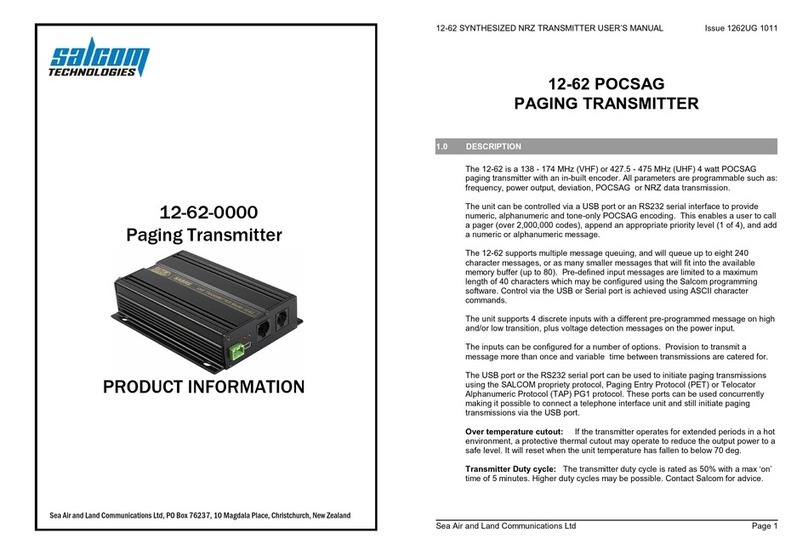
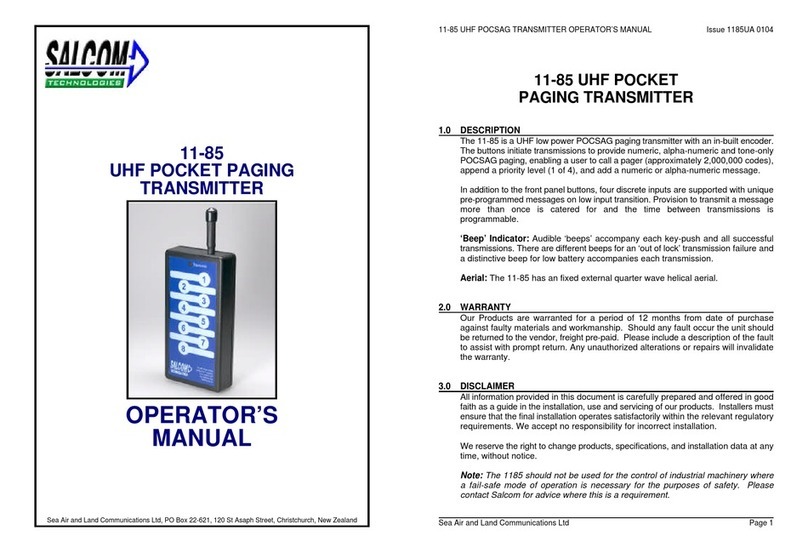
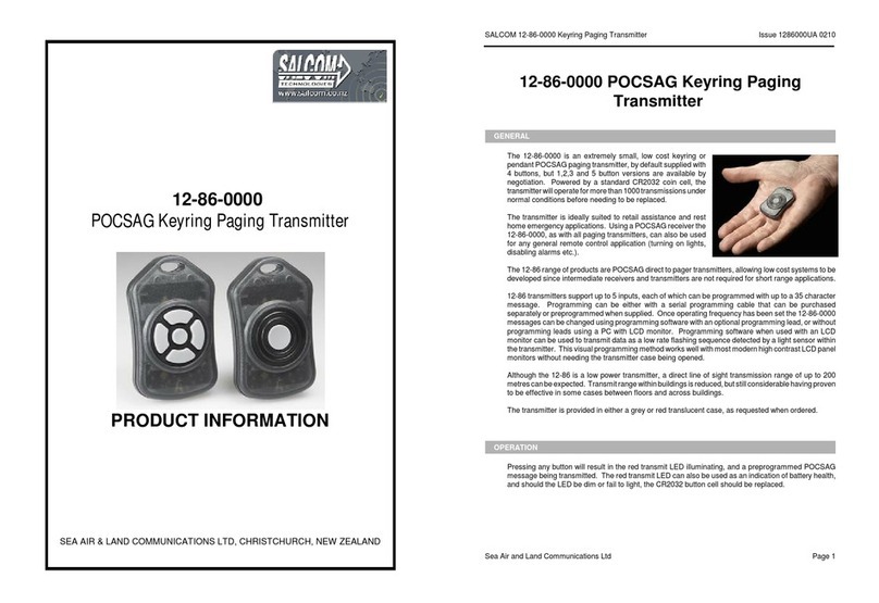
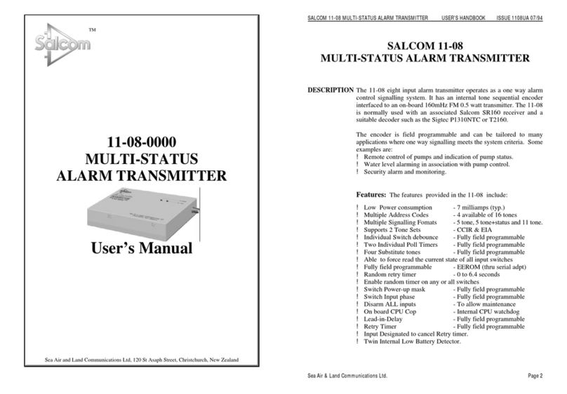
1.0 DESCRIPTION: The Salcom 11-22 is a 4w VHF narrow band FM Transmitter using
±5kHz deviation on the VHF 25kHz channel spacing Bands, 148-165MHz and ±2.5kHz
deviation on the 12.5kHz channel spacing Bands, 138-156MHz and is the companion
transmitter to the 11-21 VHF FM Synthesized Receiver.
The 11-22 is supplied tuned to the requested frequency. A two pin power connector and
a15 pin ‘D’range plug and cover are provided standard with the transmitter. A power
supply and a range of aerials are available. Discuss this with your supplier.
2.0 OPTIONS: Special options are available and can be ordered with the 11-22 or retro-
fitted by your supplier:-
!600Obalanced input when T1 fitted.
!Transmitter output power adjustable 50mW - 4W
!Multi-channels available, talk with your supplier.
!Frequency control via I²C or RS232 input is possible utilizing an external
processor on other equipment.
3.0 SETUP INSTRUCTIONS
3.1 Deviation on data source: When transmitting a constant level tone from a
modem or tone encoder use TX1 input (Comms connector pin3) and set the line
level to ±4kHz deviation with the modulating source (i.e. modem idle tone) with
RV4.
3.2 Deviation on speech source: If an uncompressed varying level modulation (i.e.
speech) is being transmitted, then the TX2 input (Comms connector pin9) can
be used. Set RV3 for ±3kHz deviation when transmitting lowest input level.
Important: The 11-22 adjustments have been factory set to ensure that it will comply
with specified emission standards and controls other than RV3 & RV4 should not be
touched.
4.0 INSTALLATION: A screwdriver to connect the power socket, and a soldering iron to
connectthe D15 communications plug and the aerial, are required for the installation
procedure.
4.1 Connections:
AERIAL SOCKET
Connects to the aerial (½ wave dipole or yagi) via a BNC plug and 50Ocoaxial cable.
POWER PLUG
Connects to +12V supply and ground. The polarity is marked on the 11-22 case
COMMUNICATIONS SOCKET
Pin 1
Pin 10 Earth connections.
Pin 2
Pin 4 No connections.
Pin 13
Pin 3 Tx Audio1 input, 10KOunbalanced, adjustable via RV4 (TX1 sens).
Pin 5 PTT. Earth to initiate a transmission.
Pin 6 Transmit Data input RS232 format, 0-5V logic.
Pin 7 High/Low power control. (Contact Salcom for application)
Pin 8
Pin 15 +13.5V supply.
Pin 9 TX2 Input. 10KOunbal. 5mV - 5V, sensitivity adjustable via RV3 (TX2
Sens).
Pin 11 600Obalanced input when T1 fitted, Link JU1 to select Tx1 or Tx2
Pin 12 amplifier.Sensitivity adjustable via RV3 (TX2 sens) or RV4 (TX1 sens).
Pin 14 Receive data. RS23 format, 0-5V logic.
5.0 OUTPUT: The transmitter can be operated continuously provided that the supply voltage
is limited to 13.5 volts. It is critical that the aerial is OK and the VSWR is below 2.0. Steps
must be taken to conduct heat from Q11 heatsink or from the case adjacent to Q11 heatsink
mounting.
6.0 OPERATING REQUIREMENTS:
!Supply voltage: +13.5V (12V nominal)
!Operating temperature range: -10EC to +60EC
!Mount in a dry position away from loud noise or vibration
7.0 LED INDICATORS: Two indicator LED's are visible on the top of the case.
(1) Green Power LED shows power is present at the 11-22.
(2) Red Tx LED lights when the 11-22 is transmitting.
8.0 REPROGRAMMING The 11-22 can be re-programmed by a supplier with the appropriate
programming facilities to another frequency in the same band.
9.0 MOUNTING: Mount the case using the two holes provided in the lid and clip the 11-22 into
position on the lid. Secure with the two self tappers to make positive electrical contact
between the case and lid and prevent RF recirculation.

11-22-0000 SYNTHESIZED VHF TRANSMITTER OPERATOR’S MANUAL Issue 0198 11-22-0000 SYNTHESIZED VHF TRANSMITTER OPERATOR’S MANUAL Issue 0198
Sea Air and Land Communications Ltd Page 3 Sea Air and Land Communications Ltd Page 4
10.0 WARRANTY: Our Products are warranted for a period of 12 months from date of purchase
against faulty materials and workmanship. Should any fault occur the unit should be returned
to the Vendor, freight pre-paid. Please include a brief description of the fault to assist with
prompt return. Any unauthorized alterations or repairs will invalidate the warranty.
10.0 DISCLAIMER: All information provided in this document is carefully prepared and offered
in good faith as a guide in the installation, use and servicing of our products. Installers must
ensure that the final installation operates satisfactorily within the relevant regulatory
requirements. We accept no responsibility for incorrect installation. We reserve the right to
change products, specifications, and installation data at any time, without notice.
SPECIFICATIONS
Frequency Bands 138-156MHz , 148-165MHz,
Type of Emission FM ±5kHz (* ± 2.5kHz) deviation
1
25kHz (* 12.5kHz) channel spacing
1
Power Output 50mW to 4W variable
Power Requirements
13.5V nominal, operates 10V to 15.5V
Transmit: 750mA typ @ 4W Output Power
900mA max, 13.5V
Standby: 3mA (LED current)
Modulation
Deviation: ±5kHz (* ± 2.5kHz) max.
1
Sensitivity: TX1 30mV/10K
TX2 5mV/10K
CTCSS 300mV/2MO
Passband: TX1,2 0.3-3kHz
CTCSS 67-250Hz
Optional: 600Obal. TX1,TX2
Oscillator Crystal 9.6MHz
Stability ±5ppm -10EC to 60EC
Synthesizer Lockup 50mSec
No of Channels 100 pre-programmable within 6MHz B/W
Spurious Outputs -26dBm max.
Overtemp Protection 70EC Transmitter Output
Transmit Enable Ground ‘PTT’, 5mA source
Type Acceptances
Case Dimensions 140 x 106 x 32mm
Table 1:Switch settings table 00 to 49
11-22-0000 SYNTHESIZED VHF TRANSMITTER OPERATOR’S MANUAL Issue 0198 11-22-0000 SYNTHESIZED VHF TRANSMITTER OPERATOR’S MANUAL Issue 0198
Sea Air and Land Communications Ltd Page 5 Sea Air and Land Communications Ltd Page 6
Table 2: Switch settings table 50 to 99
SEA AIR & LAND COMMUNICATIONS LTD
PO Box 22-621, 120 St. Asaph Street, Christchurch, New Zealand
Phone: (03) 379-2298 Fax: (03) 365-1580 Email: [email protected]

Other Salcom Transmitter manuals

Salcom 11-85-0000 User manual

Salcom

Salcom 11-85-0000 User manual

Salcom 11-24-0000 User manual

Salcom

Salcom 11-24-0000 User manual

Salcom 12-62-0000 User manual

Salcom

Salcom 12-62-0000 User manual

Salcom 20-62 User manual

Salcom

Salcom 20-62 User manual

Salcom 12-62 POCSAG User manual

Salcom

Salcom 12-62 POCSAG User manual

Salcom 11-08-0000 User manual

Salcom

Salcom 11-08-0000 User manual

Salcom 11-85 User manual

Salcom

Salcom 11-85 User manual

Salcom 12-86-0000 User manual

Salcom

Salcom 12-86-0000 User manual

Salcom 12-86-9000 User manual

Salcom

Salcom 12-86-9000 User manual

Salcom 12-86-9000 User manual

Salcom

Salcom 12-86-9000 User manual

Salcom 12-86-0000 User manual

Salcom

Salcom 12-86-0000 User manual

Popular Transmitter manuals by other brands

Vega VEGABAR 86 Quick setup guide

Vega

Vega VEGABAR 86 Quick setup guide

Ditel KOS1605P user guide

Ditel

Ditel KOS1605P user guide

AMG AMG4681R-CWDMn instruction manual

AMG

AMG AMG4681R-CWDMn instruction manual

Honeywell 5802mn2 - Ademco Wireless Panic Installation and setup guide

Honeywell

Honeywell 5802mn2 - Ademco Wireless Panic Installation and setup guide

König Electronic VID-TRANS220KN manual

König Electronic

König Electronic VID-TRANS220KN manual

Siemens SITRANS L Series Compact operating instructions

Siemens

Siemens SITRANS L Series Compact operating instructions

Harris Platinum Z2 CD manual

Harris

Harris Platinum Z2 CD manual

Labom CI4 Series operating instructions

Labom

Labom CI4 Series operating instructions

elero LumeroTel-915 operating instructions

elero

elero LumeroTel-915 operating instructions

Status Instruments SEM310 user guide

Status Instruments

Status Instruments SEM310 user guide

Vivax vLoc-9800 User handbook

Vivax

Vivax vLoc-9800 User handbook

Sennheiser SI 1013 manual

Sennheiser

Sennheiser SI 1013 manual

Sytech SY-1534BT user manual

Sytech

Sytech SY-1534BT user manual

FMUser CZH-T200 user manual

FMUser

FMUser CZH-T200 user manual

MG M3SVS instruction manual

MG

MG M3SVS instruction manual

Badger Meter Orion Universal 1 Transmitter Installation data

Badger Meter

Badger Meter Orion Universal 1 Transmitter Installation data

Dräger Polytron 8000 Instructions for use

Dräger

Dräger Polytron 8000 Instructions for use

JUMO MIDAS S21 Ex operating manual

JUMO

JUMO MIDAS S21 Ex operating manual

manuals.online logo
manuals.online logoBrands
  • About & Mission
  • Contact us
  • Privacy Policy
  • Terms and Conditions

Copyright 2025 Manuals.Online. All Rights Reserved.