TX25/50 FM Transmitter technical manual page 7
Installation and setup
2.1 FREQUENCY SETUP
The Frequency can be set on the transmitter in one of two ways:
1. From internal direct reading decimal switches on the main board
2. From the front panel LCD display and front panel buttons.
Many radio regulatory bodies stipulate that the transmitters parameters including the frequency must not be easily
changed from the front panel. To meet this requirement you will need to set the frequency internally with the dial
switches.
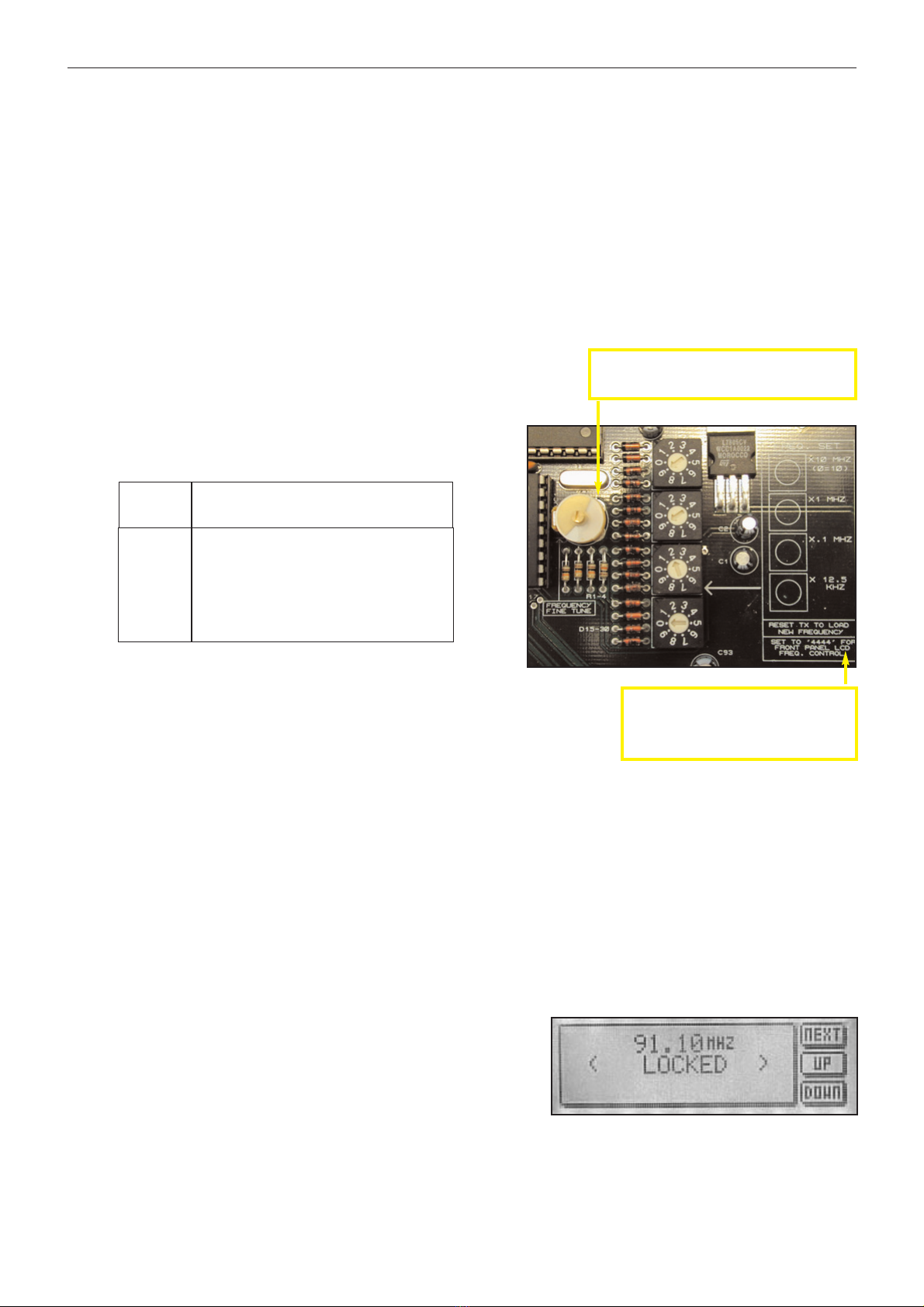
The switches have a silkscreen diagram next to them on the board (see diagram below) clearly indicating what
each switch represents.
The top dial switch represents the value selected x 10 Mhz with the exception of ‘0’ which represents 10 so when
selected would equal 100 Mhz.
The second dial switch represents the value selected x 1 Mhz.
The third dial switch represent the value selected x .1 Mhz (100 KHz)
The bottom switch represents the value selected x .0125 Mhz (12.5 KHz)
For example:
FREQ SWITCHES (MHZ)
X10 X1 X.1 X.0125
87.90 ‘8’ ‘7’ ‘9’ ‘0’
98.75 ‘9’ ‘8’ ‘7’ ‘4’
100.00 ‘0’ ‘0’ ‘0’ ‘0’
104.225 ‘0’ ‘4’ ‘2’ ‘2’
108.00 ‘0’ ‘8’ ‘0’ ‘0’
As you can see, the switches directly read the frequency with the exception of
frequencies above 100 Mhz, where the top switch being set at ‘0’ represents
‘10’. The X0.125 ‘offset’ switch is only used when you want to provide a shift to
the carrier of between 12.5 KHz and 112.5 KHz. Note that setting the switch
on 8 or 9 will have the same effect as setting the previous switch (100 KHz) 1
position higher, as 8 represents 100 KHz on the 12.5 KHz switch. 8 x 0.125MHz = 0.1MHz = 100KHz
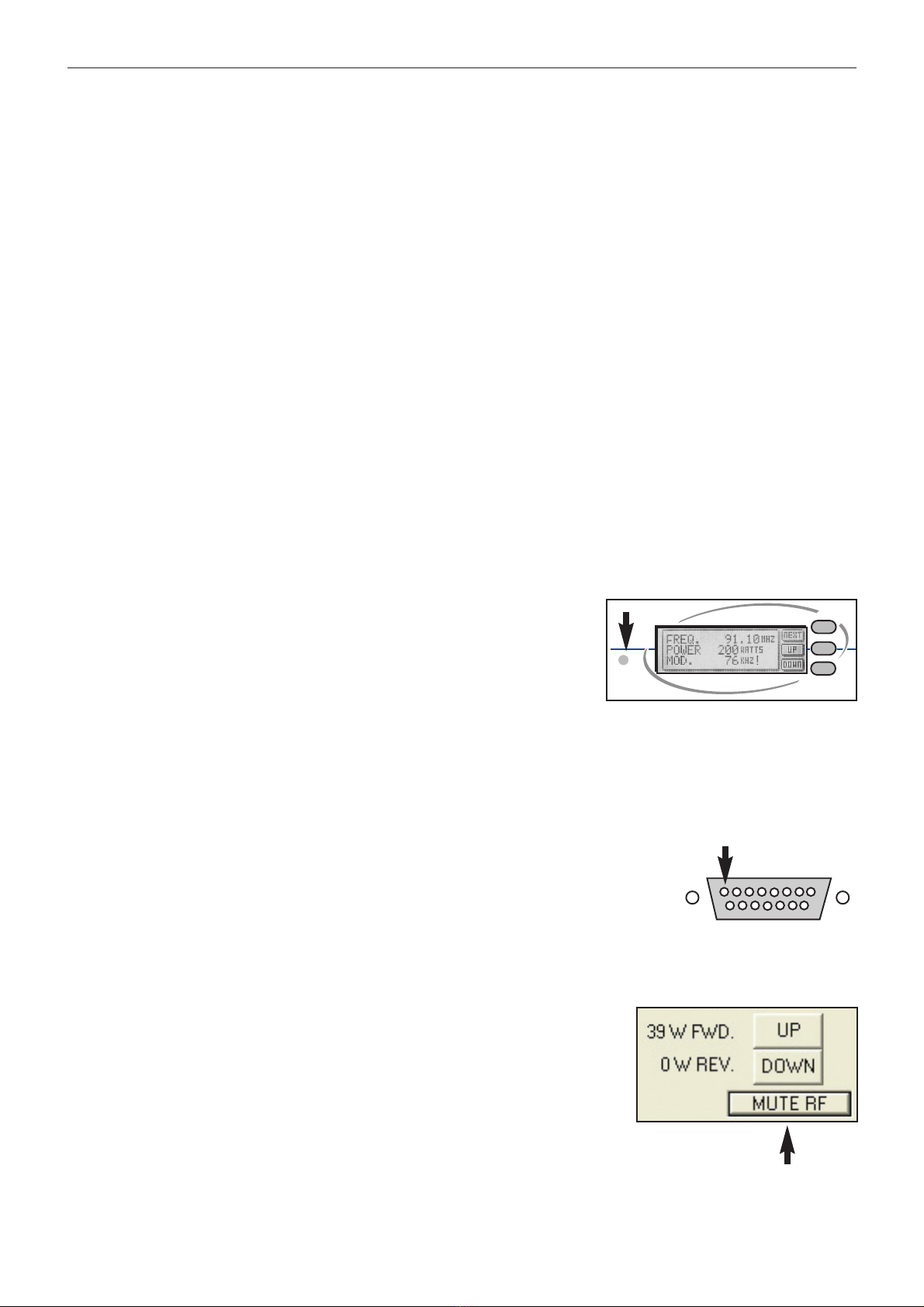
The LCD display on the front panel will display the frequency that you have set on the internal switches. If you try
to adjust the frequency with the front panel up / down buttons you will get a ‘ NOT ALLOWED ‘ message appear-
ing on the LCD display. This protects against unauthorized front panel frequency changes when the frequency
has been set internally with the dial switches.
The TX will load the switch values at power up. You will need to remove the mains power to the transmitter
and then reapply it if you want to change the frequency by using the direct reading switches
LCD front panel frequency selection.
If you want to control the frequency from the front panel LCD control
system you will need to set the internal switches to 4440. The trans-
mitter will pass frequency control to the LCD control system and the
frequency can be moved up and down by pressing the NEXT button
until the frequency menu is displayed. The other two buttons control
the UP and DOWN frequency selection. PLL lock status is also dis-
played on this screen.
The LCD readout will only display frequencies in 100Khz steps. Any frequency offsets derived from the
internal 12.5KHz offset switch will not show on the LCD. Consult a frequency counter if using offsets.
Note that some pcb’s have “set to 4444 for
front panel LCD control”. This is an error that
will cause a +50KHz offset to the frequency
set on the LCD screen. Please set to 4440
unless you specifically want the offset.
Frequency selection switches on main board
Fine frequency control. Do not adjust unless you
know what you are doing. Consult advanced setup
section of manual for more information.