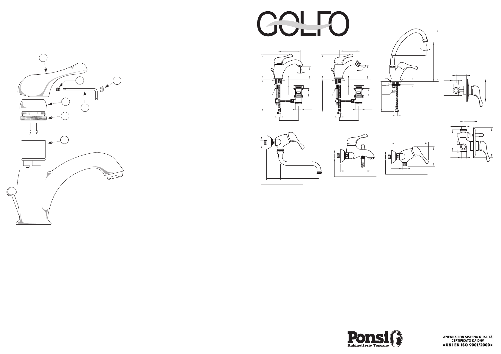
MISCELATORI DA LAVABO-BIDET-LAVELLO Art. 241, 243, 248
BASIN-BIDET-SINK MIXERS
- Svitare le borchie (2) dai rispettivi attacchi eccentrici (1);
- Guarnire le filettature con teflon oppure canapa e pasta per giunti filettati
- Avvitare gli attacchi eccentrici (1) sulle prese a muro, posizionandoli ad un
interasse di 150 mm
- Installare le borchie; quindi posizionare il corpo, serrando le calotte (3) con
una chiave da 30 mm
- Unscrew the two flanges (2) from the unions (1)
- Pack the union threads with teflon or hemp + grease
- Screw in the unions (1) on the wall sockets (suggested centre distance between the
sockets: 150 mm)
- Screw the flanges on unions. Place the mixer body and tighten nuts (3) using a 30 mm
wrench.
MISCELATORI A PARETE Art. 242, 244, 247
WALL MOUNTED MIXERS
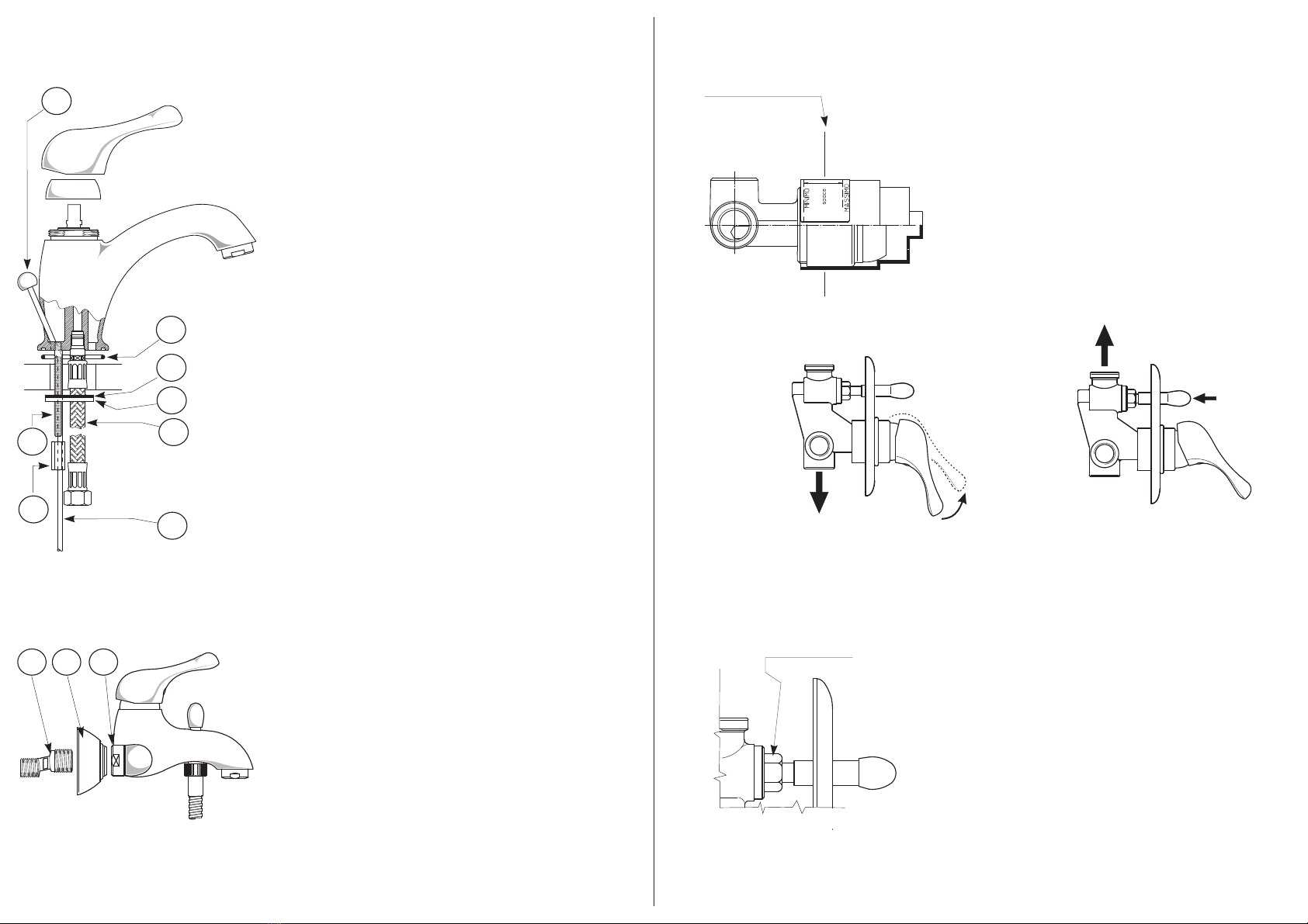
INSTALLAZIONE INSTALLATION
MISCELATORI DA INCASSO PER DOCCIA Art. 245 - 246
CONCEALED SHOWER MIXERS
- Posizionare il miscelatore in modo che il filo del rivestimento sulla
parete finita sia compreso tra le due linee riportate sulla protezione.
- Rimuovere la protezione e inserire la borchia a parete.
- Montare la leva eseguendo le operazioni indicate nella pagina
precedente.
- Dopo aver smontato la leva (vedere ), svitare il
pomolo (2) premendo contemporaneamente contro la sede.
Togliere la borchia (1).
- Svitare il deviatore (3) utilizzando una chiave a tubo di 19 mm.
- Si consiglia di non intervenire sui componenti interni del deviatore
e di richiedere il ricambio completo presso i nostri rivenditori.
nell’ultima pagina
- Remove handle (see instructions on the last page). Push knob (2) against
seat. Without releasing pressure, unscrew knob
- Remove cover plate (1).
- Unscrew diverter (3) using a 19 mm spanner
- We recommend to replace the entire diverter unit and not separate
components
- When installing the concealed part of the mixer, please observe the given
centre-to-wall distances shown on the drawing and printed on the mixer
protecting cover.
- Remove protecting cover and insert flange
- Install handle following the 'handle installation' instructions in the previous
page.
AUTOMATIC DIVERTER: REPLACEMENT
ART. 246 - DEVIATORE AUTOMATICO: SOSTITUZIONE
INSTALLAZIONE INSTALLATION
7
6
5
43
8
1
2
1 2 3
Filo rivestimento esterno
Wall lining
AVVERTENZE
WARNINGS
EROGAZIONE PRIMARIA
PRIMARY WATER EROGATION APERTURA LEVA
LEVER OPENING
EROGAZIONE SECONDARIA
SECONDARY WATER EROGATION PREMERE POMOLO
PUSH KNOB
- Svitare il pomolo (1) dall’asta (2), ed inserire quest’ultima nel corpo miscelatore
dal basso verso l’alto. Quindi rimontare il pomolo.
- Avvitare e serrare a fondo i flessibili (3) e i tiranti (4)
- Inserire la guarnizione O-Ring (5) nella relativa sede, e posizionare il miscelatore
sul piano del sanitario
- Inserire la guarnizione (6) e la staffa (7)
- Serrare i dadi (8) con una chiave da 9 mm
- Collegare i flessibili (3) alla rete idrica
- Installare il congegno di scarico
- Inserire e posizionare il morsetto sull'asta di comando congegno, in modo da
non far urtare, a tappo dello scarico sollevato, il pomolo (1) sul corpo.
- Unscrew knob (1) from rod (2). Insert rod from bottom upwards inside mixer body. Then
screw knob in rod
- Screw in and tighten feed pipes (3) and threaded tie rod (4)
- Insert O-Ring (5) in its seating and place the mixer on the basin/bidet/sink deck
- Insert gasket (6) and clamp (7)
- Tighten nut (8) using a 9 mm wrench
- Connect the pipes to the water supply
- Install the pop-up waste
- Connect vertical and horizontal rods using the clamp provided and adjust in order to
prevent knob (1) from fouling the mixer surface.
NOTA/
- Si consiglia l’adozione di rubinetti filtro a parete per evitare l’inclusione di
corpi estranei.
NOTE :
- We suggest to install filter taps in order to prevent solid particles from damaging the mixer
internal components.
Chiave 19 mm.
19 mm. spanner
3
2