Ponsi Rubinetterie Toscane ITALIA Series Operating and maintenance manual

ART. 63
210± 10
G 1/2"
G 1/2"
Min 45
Max 75
100
210± 10
Min 45
Max 75
G 1/2"
240 x 100
62
140± 10
Min 45
Max 75
G 1/2"
240 x 100
62
ART. 64 ART. 66
Revisiome Giugno 2010
SOSTITUZIONE CARTUCCIA
SOSTITUZIONE ROMPIGETTO
CARTRIDGE SUBSTITUTION
FLOW GUIDE REPLACEMENT
- Utilizzare un utensile a lama sottile per estrarre la placchetta (1) dalla propria sede.
- Svitare il grano (2) con la chiave (3), quindi sfilare la leva (4).
- Svitare la calotta sferica (5).
- Svitare la ghiera (6) con una chiave di 24 mm, quindi sostituire la cartuccia (7).
- Nel rimontare la ghiera (6), si consiglia di serrare con una chiave dinamometrica
regolata su 0.8 Kgm max.
Estrarre il rompigetto da sostituire con una pinza (A). Inserire il rompigetto di ricambio per
mezzo di una mazzuola in gomma (B)
- Raise the cap (1) from its seating, using a thin-bladed tool.
- Unscrew dowel (2) using the Allen wrench supplied (3)Then raise handle (4).
- Unscrew dome (5).
- Unscrew blocking nut (6) using a 24 mm spanner. Replace cartridge (7).
- Tighten blocking nut (6), if possible using a torque wrench (max. setting 0,8 kgm)
Remove flow guide using pliers (A). Insert new flow guide using a rubber mallet (B)
MONTAGGIO LEVA
- Inserire la leva (4) sull’asta della cartuccia (7).
- Serrare il grano (2) per mezzo della chiave in dotazione (3) ed infine inserire
placchetta (1) nella propria sede.
HANDLE INSTALLATION
Consigliamo di conservare la chiave per effettuare manutenzioni successive.
- Insert handle (4) on the cartridge stem (7).
- Tighten dowel (2) using the Allen wrench supplied (3) and insert cap (1).
Keep wrench available in case of further necessity.
4
2
3
1
5
6
7
3
1
2
4
5
6
7
Codice ricambi
Spare parts code
K27
A
B
Codice ricambi
Spare parts code
K27
125
Ch.12
10°
60
165
350
Max 40
ø 35
G 3/8”
65x48
125
Ch.12
10°
165 - 215 - 265
275 - 325 - 375
350
Max 40
ø 35
G 3/8”
65x48
100 - 150 - 200
210
Ch.12
10°
165 - 215 - 265
275 - 325 - 375
350
Max 40
ø 35
G 3/8”
65x48
100 - 150 - 200
ART. 57 ART. 65/1 ART. 58 ART. 59
Serie
ITALIA
GARANZIA : Le informazioni sulla garanzia e le istruzioni di manutenzione ad uso dell’utente sono inserite nel tagliando di controllo.
WARRANTY : Information about warranty and maintenance instructions for users are listed in the warranty card included in each item box.
AVVERTENZE
WARNINGS
- L'impianto deve essere dotato di adeguati dispositivi di filtrazione dell'acqua e di regolatori di pressione per ovviare a eventuali
"colpi d'ariete" dovuti a sbalzi della stessa.
- La pressione consigliata per l'utilizzo è di 3 bar, max 5 bar.
- Provvedere al risciacquo delle tubazioni di adduzione idrica prima di effettuare l'installazione dei miscelatori.
- La pulizia deve essere effettuata con sapone diluito in acqua; i prodotti devono essere asciugati con un panno morbido per impedire
la formazione di depositi di calcare.
- I depositi di calcare od altre impurità nei filtri degli aeratori devono essere rimossi, con frequenza
mensile, per mezzo di appositi prodotti o per immersione per mezza giornata in soluzione di acqua
ed aceto (80/20).
- Per l'installazione di ogni articolo, seguire le raccomandazioni riportate nella pagina corrispondente.
- The plumbing installation should be fitted with adequate water filters and pressure regulation devices in order to avoid misfunctioning in case of pressure shocks
- Advised pressure is between 3 and 5 bars
- Flush pipelines thoroughly before installing mixers
- Clean the mixers with soap mixed with water; products must be dried with a soft cloth in order to prevent limescale deposits
- Limescale deposits or other impurities in filters of flow guides must be removed monthly by using appropriate products or by immersing in water/vinegar solution (80/20)
- For each mixer installation, please follow instructions in corresponding page.
RUBINETTERIE TOSCANE PONSI S.p.A.
I - 55049 VIAREGGIO (LU) - Via A. VOLTA, 2
Tel. (+39) 0584 - 427611 - Fax 0584 - 46117(+39)
www.ponsi.com E-Mail: info@ponsi.com
100
Ch.12
165
350
Max 40
ø 35
G 3/8”
65x48
45°
55
MANUTENZIONE
MAINTENANCE
INSTRUCTION FOR INSTALLATION AND MAINTENANCE
for installators only
ISTRUZIONI PER INSTALLAZIONE E MANUTENZIONE
ad uso personale tecnico

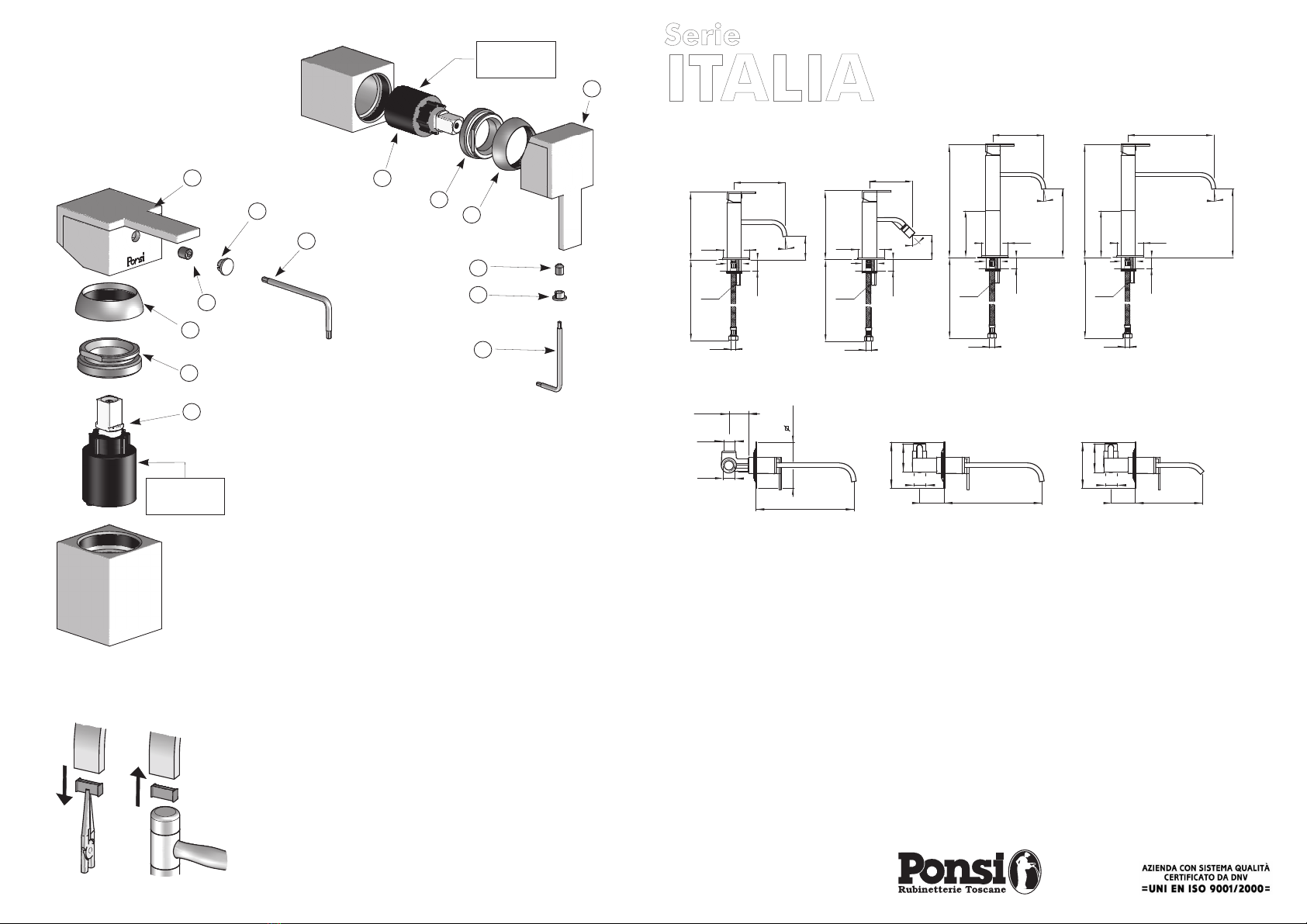
- Avvitare e serrare a fondo i flessibili (1) e il tirante (2)
- Inserire nella piastra di base (3), la guarnizione (4) e posizionare il
miscelatore sul piano del sanitario
- Inserire la guarnizione (5) e la staffa (6)
- Serrare il dado (7) utilizzando una chiave da 12 mm
- Collegare i flessibili (1) alla rete idrica
- Installare il congegno di scarico.(solo art. 57/T e 57/Q)
- Screw and tighten feed pipes (1) and threaded tie rod (2)
- Insert base ring (3) and O-ring (4), then place the mixer on the basin/bidet
deck
- Insert gasket (5) and clamp (6)
- Tighten nut (7) using a 12 mm wrench
- Connect pipes (1) to water supply
- (for art. 57/T and 57/Q only) Install pop-up waste.
NOTA/NOTE :
- We suggest to install filter taps in order to prevent solid particles from
damaging the mixer internal components.
- Si consiglia l’adozione di rubinetti filtro a parete per evitare
l’inclusione di corpi estranei.
MISCELATORI DA LAVABO-BIDET
BASIN-BIDET MIXERS
Art. 57/S, 57/T, 57/Q65/S1, 65/T1, 65/Q1
MISCELATORI DA INCASSO PER LAVABO
Art. 63/S, 63/T, 63/Q
CONCEALED WASHBASIN MIXERS
G1/2”
Interasse minimo consigliato = 13 cm
Miscelatore da
incasso per lavabo
Concealed washbasin
mixer
Acqua
calda
Hot
water
Minimum suggested center distance = 13 cm
Acqua
fredda
Cold
water
1
2
3
1
Il collegamento fra miscelatore e bocca di erogazione
è incluso nella confezione: pertanto i due
componenti possono essere collocati in qualunque
posizione reciproca. Nella figura è mostrato uno schema
di installazione con raccorderia standard:
1- Curva G1/2” maschio - G1/2” femmina
2- Tubo congiunzione G1/2” maschio - G1/2” maschio
3- Curva G1/2” femmina - G1/2” femmina per bocca di
erogazione
non
Connections between mixer and spout are not supplied: therefore
mutual position is not given. The picture shows an installation
scheme including standard connectors:
1 - 1/2" male - 1/2" female elbow
2 - 1/2" male - 1/2" connecting pipe
3 - 1/2" female - 1/2" female elbow (for spout)
- Posizionare il miscelatore in modo che il filo del
rivestimento sulla parete finita sia compreso tra le due
linee riportate sulla protezione
- Rimuovere la protezione ed inserire la borchia
scorrevole (1)
- Inserire la bocca (2) prestando attenzione alle
guarnizioni (3)
- Orientare la bocca e bloccare il grano (4) per mezzo della
chiave a brugola (5)
- Montare la leva seguendo le operazioni indicate
nell’ultima pagina.
- Install mixer body paying attention to the min/max wall lining
distance given on the sticker
- Remove protecting cover
- Insert flange (1)
- Insert spout (2) paying attention to the washers (3)
- Set the spout in correct position and block it with dowel (4) using the
Allen wrench (5) supplied
- Install handle following the 'handle installation' instructions on the
2
3
4
5
1
MIN
MAX
LIMITIDEL RIVESTIMENTO
LIMITSFOR WALL LINING
LIMITESDU REVÊTEMENT
PLATTENBELAGESGRENZENN
AVVERTENZE
ADVICE
UTILIZZARE QUESTOPIANO PER LA MESSA IN BOLLA
USETHIS SURFACE TO SUPPORT YOUR LEVEL
Filo rivestimento
esterno
Wall lining
IN FASE DI COLLEGAMENTO
ALLA RETE IDRICA VERIFICARE
ALLINEAMENTO ORIZZONTALE
DEL GRUPPO INCASSATO
BEFORE CONNECTING MIXER TO
SUPPLY PIPES, WE SUGGEST TO
CHECK HORIZONTAL ALIGNMENT
OF CONCEALED BODY
1
2
3
4
6
7
5
2
3
4
5
6
1
- Inserire nella piastra di base (1), la guarnizione (2) e posizionare il
miscelatore sul piano del sanitario
- Inserire la guarnizione (3) e la staffa (4)
- Serrare il dado (5) utilizzando una chiave da 12 mm
- Collegare i flessibili (6) alla rete idrica
- Insert base ring (1) and O-ring (2), then place the mixer on the basin/bidet
deck
- Insert gasket (3) and clamp (4)
- Tighten nut (5) using a 12 mm wrench
- Connect pipes (6) to water supply
/NOTE :
- We suggest to install filter taps in order to prevent solid particles from
damaging the mixer internal components.
NOTA
- Si consiglia l’adozione di rubinetti filtro a parete per evitare
l’inclusione di corpi estranei.
MISCELATORI DA LAVABO SU COLONNA
Art. 58/S, 58/T, 58/Q, 59/S, 59/T, 59/Q
WASHBASIN MIXERS ON PILLAR
MISCELATORI DA INCASSO PER LAVABO-BIDET
Art. 64/S, 64/T, 64/Q, 66/S, 66/T, 66/Q
CONCEALED WASHBASIN-BIDET MIXERS
Acqua
calda
Hot
water
Acqua
fredda
Cold
water
Per una installazione
agevole è consigliato
l’utilizzo di un raccordo
curvo in tre pezzi
For an easier
installation we suggest
to use a 3-pieces
bent union
INSTALLAZIONE INSTALLATION INSTALLAZIONE INSTALLATION
This manual suits for next models
28
Other Ponsi Rubinetterie Toscane Plumbing Product manuals
Popular Plumbing Product manuals by other brands

Graff
Graff TARGA 2309000 Instructions for assembly and use

Graff
Graff BALI 2100-LM20 installation instructions

oventrop
oventrop Regudis W GSWB Installation and operating instructions

Bradley
Bradley S19-270HD Installation

baliv
baliv KI-5150 N instruction manual

Tenzo
Tenzo NU11-CR Installation manual & users guide

A.O. Smith
A.O. Smith AO-MF-B owner's manual

Danze
Danze D500058 quick start guide

Helvex
Helvex Nuva TV-203 installation guide

Spectrum Brands
Spectrum Brands Pfister Ashfield G89-XYP Quick installation guide

Rohl
Rohl Georgian Era U.4744 Installation & user guide

Spectrum Brands
Spectrum Brands Pfister Avalon LG49-CB1 Quick installation guide