Pony4 P4 Service manual

Pony4 - Operating and Service Manual

1 Introduction 3
1.1 Description 4
1.2 Variants, specifications and options 5
2 Delivery 7
2.1 Unpacking 7
2.2 First assembly and adjustments for rider 8
2.3 Front boom assembly 10
2.3.1 Front boom assembly Pinion or crankset without motor 10
2.3.2 Front boom assembly Long frame with Pinion and motor 12
2.3.3 Front boom assembly Long frame with Rohloff and motor 16
2.4 Basic check after assembly 20
3 Operation 23
3.1 Basics 23
3.2 Vehicle 23
3.3 Load carrying 28
4 Safety 30
4.1 General 30
4.2 Visibility 30
4.3 Rider position 30
4.4 Shoes with clipless and other system 30
4.5 Load securing 30
4.6 Pre ride check 31
4.7 Ride 31
4.8 After the ride 32
5 Service 32
5.1 In general 32
5.2 Brake-in period 32
5.3 Frame and Rails 33
5.4 Boom 33
5.5 Seat and seat brackets 33
5.6 Steering and geometry alignment 33
5.7 Brakes 37
5.8 Gears 38
5.9 Suspension 38
1


1 Introduction
Dear Customer, First of all, we would like to thank you for choosing Pony4 (P4) to meet
your transportation needs. We hope you will be happy to ride any number of kilometers or miles
with our product to improve the environment on planet earth.
Our team believes that any human powered vehicle can be adapted to almost any
transportation need, and if it doesn't exist, it hasn't been developed yet.
In this manual we will go through all aspects of living with a P4 from delivery, initial
installation, alignment, safety, maintenance, and finally durability and warranty. Because this
process can be quite complex, we have marked the important parts with the word CAUTION: For a
better understanding, you will also find links to our video channel: Pony4bike in some cases.
If you are unsure about any details in our instructions or other things related to the P4,
please visit our website. We have a lot of useful information there combined with some video
tutorials and drawings.
For components and parts from other manufacturers (e.g. internal gear systems, brakes, etc.),
we recommend that you study those manufacturers' specific manuals. These manuals contain
specific procedures for assembly, disassembly and maintenance of these parts. Familiarize yourself
with them, as failure to follow these procedures may result in damage to the parts and limitation of
the warranty. Please note that some tasks can only be completely performed by the manufacturers
(for example, disassembly of the internal parts of Rohloff hub gears).
3

1.1 Description
P4 is considered as a bicycle due to human power (and limited electric assist) in a lot of
countries. However, sometimes local rules may differ, so familiarise yourself with them and contact
the authorities on this matter. For some parts you will find great similarity with bicycles and
recumbents such as wheels, transmissions, drum brakes, seat, etc. Other parts will be completely
new for you, for example leaf springs, rear axle, etc. For these parts we will have a more detailed
review in the manual. Since each P4 bike is built to a specific order with optional extras, some parts
may vary from bike to bike.
Basic important P4 parts with terminology can be seen at followed scheme:
4
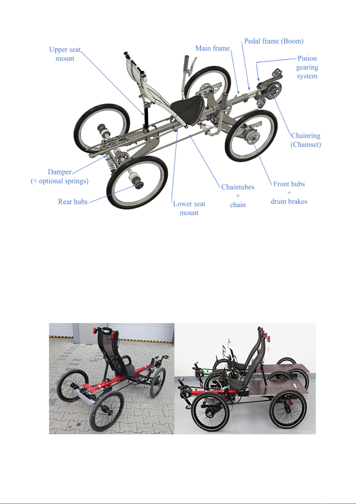
Fig. 1. Pony4 basic scheme with terminology
1.2 Variants, specifications and options
We have developed three basic variants of the P4. All variants share the same principle of
frame construction and transmission. For light cargo applications there is a SHORT FRAME /
LIGHTWEIGHT version with one damper on the rear axle. For compact cargo with more weight,
we have a SHORT FRAME / HEAVY LOAD version with two dampers with optional steel springs
on the rear axle. And finally for bulkier and more heavy cargo we have the LONG FRAME /
HEAVY LOAD version with two dampers and optional steel springs on the rear axle.
Fig. 2. Pony4 LIGHTWEIGHT (left) and HEAVY LOAD (right) with Flat Cargo Platforms
5

Fig. 3. Pony4 HEAVY LOAD Short -Cargo Box Low (L), Cargo Box High (R)
Fig. 4. Pony4 HEAVY LOAD Long with Cargo Box Low
Pony 4 is equipped with 90 mm front drum brakes with improved cooling. Rear axle is
without brakes. For transmissions, we offer Pinion gearboxes in two variants with one chain drive.
Second option is the Rohloff hub in the middle position with two chains. E-assist, a pedelec system,
is offered in several variants. Simple version, combined with Pinion, is mounted in the front of front
leaf springs with 250 W motor and 30 Nm or 45 Nm torque levels . For heavy cargo and more hilly
terrain a mid-drive motor located in cranks together with Rohloff is better suited.
You will find detailed variants and parameters description on Fig.5. Complete options list can be
found in order form at followed link:
https://www.pony4.bike/wp-content/uploads/2021/02/PONY4-ORDER-FORM.pdf
6

Fig. 5. Pony4 variants and basic parameters
2 Delivery
All Pony4 bikes can be ordered directly from us or through our dealers. In the case of direct
sales, each bike is packed in an oversized cardboard box and is assembled with the exception of the
seat, boom (in the case of long frames) and specific accessories (mudguards, etc.). Handlebars are
attached and folded. We use recycled materials for packaging of disassembled parts and spare parts
to avoid possible damage. These boxes are usually hot-glued to the outer box to prevent movement.
To avoid having to wrap the outer carton during shipping, we use empty cartons inside to fill the
empty space. Check all boxes inside the packaging for parts before discarding them when
unpacking.
2.1 Unpacking
Unpacking is simple. First cut the outer straps, then cut the tape on the top to open the box.
Remove the seat which is usually fixed with zip ties to the wheel and handlebars. Check for other
parts possibly attached to P4. After that it is better to lift the P4 from the box. Then inside of the big
box there will be smaller paper boxes with other parts including extra options (usually manual,
boom with chainset, mudguards, etc.). LONG FRAME P4 versions have a pedal frame (boom) with
cranks and chainset removed from frame. Boom with the option of Pinion gearbox is packed inside
front leaf springs due to connection of shifting cables. Some parts are fragile when not mounted so
handle them with care (for example composite mudguards).
Unpacking can be seen in the first part of this tutorial video:
PONY4 - unpack and prepare for your first ride
7
2.2 First assembly and adjustments for rider
First assembly is rather easy and intuitive if you follow this order: Seat, Handlebars, Pedal
frame, Chain, Brakes, Mirrors.
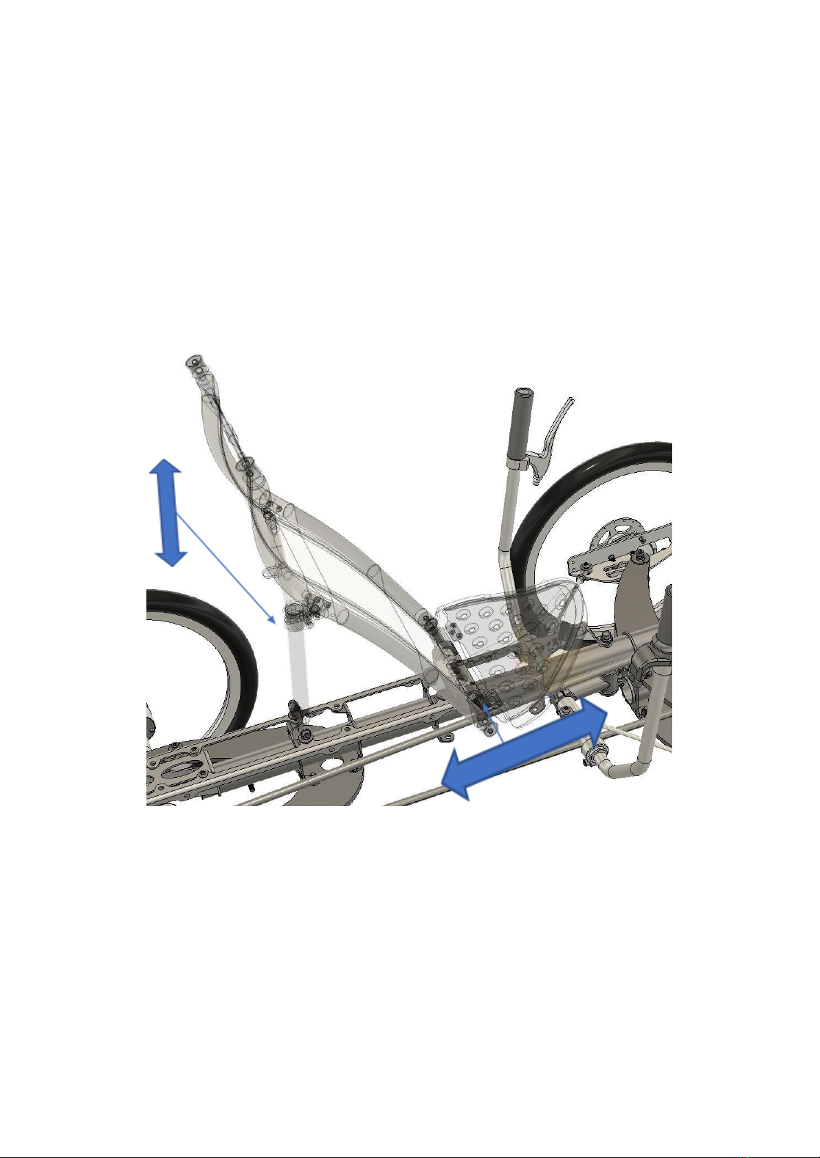
Seat is attached to the frame in two places. Seat lower area is resting on a conic shaped silentblock.
Fig. 6. Seat adjustment movements
8

Fig. 7. Seat adjustment - upper mount
Fig. 8. Seat adjustment - lower mount, attached on the seat for transport (L)
different positions of the seat in the rails (R)
9
Table of contents


