Venture Cycle LandRider User manual

ASSEMBLYINSTRUCTIONS
Version 4

ASSEMBLY TIPS
If you carefully follow each step in order, assembly should take approximately 30 minutes.
We recommend that you have a friend help you assemble the LandRider.
Relax and be patient. Your safety is important.
CUSTOMER SERVICE
If you have any questions please call LandRider at: 1-800-945-5335 or email us at
service@landrider.com
1
WARNING: These Assembly Instructions are a supplement to your Owner’s Manual.
This information is limited to the assembly instructions for the LandRider and does
not include general safety and product information on the LandRider or bicycling.
For a complete understanding of the LandRider and all warnings and cautions, you
must thoroughly read and completely understand your LandRider Owner’ s Manual.
Copyright: Venture Cycle, LLC. 2001

STEP 1: ASSEMBLY PREPARATION
A) Using a pair of scissors, carefully cut all the ties holding the bike parts together.
DO NOT USE A BLADE, AS THIS IS DANGEROUS AND COULD PUNCTURE THE TIRE.
B) Carefully free Front Wheel which is supported by Crank Arm and Handlebar Stem.
DO NOT REMOVE THE PROTECTIVE WHITE CARDBOARD SLEEVES WRAPPED AROUND
THE FRAME UNTIL THE BIKE IS COMPLETELY ASSEMBLED.
C) Remove the protective caps from the Wheel Hubs on the Front and Rear Wheels.
STEP 2: PRE-ASSEMBLY CHECK
Lay out all the components and tools for a pre-assembly check list. If any parts are missing, call
LandRider at: 1-800-945-5335.
Pre-Assembly Check List
Main Box
1. Frame Assembly (including Handlebars)
2. Seat Assembly (including Seat Post)
3. Front Wheel Assembly
Small Box
4. Pedal (right)
5. Pedal (left)
6. Front Wheel Quick Release for Front Wheel Assembly
2
7. Wrench (14/15 mm)
8. Multi Tool Set (includes 2,2.5,3,4,5 & 6 mm Allen Keys, Philips head and regular screw driver)

STEP 3: MANUAL
Open the Owner’ s Manual to page 3 which shows a photo of the LandRider identifying all the
components. This will help you while assembling the LandRider.
STEP 4: STAND FRAME UP
Carefully stand the bike up using the Fork ends as a stand. Make sure the Fork is facing forward
as per the drawing below.
3
FIG. 1
Fork Protective Spacer
( for shipping only )

4
STEP 5: CONNECTING HANDLEBAR
A) Remove the protective cardboard and rubber cap from the bottom of the Handlebar Stem Cone. (See FIG. 2).
B) Remove plastic plug ontop of Stem Bolt. BeforeinsertingtheSteminto the Head Tube youmayneedto
loosen theStem Boltslightly 1-3turns counterclockwise so the Stem Cone will fit into theHead Tube (See FIG. 2).
C) Now insert the Handlebar Stem into the Head Tube of the bicycle Frame so there is approximately
2 inches from the top of the Head Tube to the Handlebar Tilt Arm. (See FIG. 2 & 3). Do not raise the Stem
above Minimum Insertion Line. The approximate maximum Stem height is 3.75”. Firmly tighten clockwise the
Handlebar StemBolt withthe large6mm AllenKey. (See FIG. 2).You willadjust the Handlebarlater.
YES NO!
FIG. 4 FIG. 5
FIG. 2 FIG. 3
D) Before going any further, make sure the Brake and AutoMax cables are not tangled and Cables are
correctly engaged into Brake Handles. (See FIG. 4 & 5). You willadjust the Handlebar later.
See pages 14-16 for a more complete understanding of the Handlebar if necessary.
2.0”
Minimum
Insertion Line
Head Tube
Handlebar Stem
Bolt(6mm)
3.75”
Stem Bolt Plug
Stem Cone Remove
Cap

5
STEP 6: CONNECTING SEAT POST
The action of the Quick Release Cam squeezes the Seat Collar around the Seat Post to hold the Seat Post
securelyin place.The amount ofclamping forceis controlledby the TensionAdjustingNut. Turningthe
Tension Adjusting Nut clockwise while keeping the Quick Release Lever from rotating increases clamping
force; turning it counterclockwise while keeping the Lever from rotating decreases clamping force.
A) Release the Seat Post Quick Release onthe Seat Tube by opening the Quick Release Lever. (See FIG. 8).
B) Insert the Seat Post into the Seat Tube and lower the Seat Post all the way (See FIG. 7). You will adjust
seat height later. Do not raise the Seat Post above Minimum Insertion Line.
C) KeepingtheSeat parallelwiththe Frameturn theTensionAdjustingNutclockwise withone handwhile
holdingtheQuick ReleaseLeverwith theother hand.Turn theTensionAdjusting Nutuntilit isastight asyou
can get it by hand. (See FIG. 8).
D) Now close the Quick Release Lever so that the Seat Post is secured in the Seat Tube. The full force of the
Quick Release Cam is required. Quick Release Lever should be turned towards Front Wheel. Check Rear
Reflector is straight and tight.
FIG. 6 FIG. 7
Rear
Reflector
IMPORTANT: If you can fully close the Quick Release and the Lever does not leave a clear imprint in the palm
ofyour hand,the tensionis insufficient.Openthe Lever;turn theTensionAdjusting Nutclockwise aquarter turn;
thentry again.If theLever cannotbe pushedall theway toa closedposition, returnthe Leverto theOPEN
position.ThenturntheTensionAdjustingNutcounterclockwiseone-quarterturnandtrytighteningthe Lever
again.
OPEN
CLOSED
Tension Adjusting Nut
Quick Release Lever
TIGHTEN
FIG.
8
LOOSEN
Minimum
Insertion Line

STEP 7: ADJUSTING FRONT REFLECTOR
Adjust Front Reflector which has been turned in for shipping. Use Philips screwdriver to loosen
Reflector Adjustment Bolt and then adjust to forward vertical position and retighten.(See FIG. 9).
STEP 8: OPENING FRONT BRAKE
You will need to release the Front Brake Arm so you can complete Step 10 and put the Front Wheel on.
A) With your right hand, squeeze the two Brake Arms of the Front Brakes together so the Brake
Cable becomes slack.
B) With your left hand, grasp the Cable close to the Cable Sleeve (See FIG. 11) and pull to the left
and then lift so the Cable Sleeve end comes out of the Swinging Brace on the Left Brake Arm. The
Front Brakes should now be open.
6
FIG. 9
Front Reflector
FIG. 10 - Closed FIG. 11 - Open
Cable
Sleeve
Brake
Arm
Reflector Adjustment Bolt
Brake
Arm
Swinging
Brace
Squeeze Squeeze
Pull
then
lift

STEP 9: TURN BIKE OVER
For steps 10, 11 & 12 we recommend you turn the bike over, balancing it on the Handlebars and
the Seat. (See FIG. 12).
STEP 10: INSERTING FRONT WHEEL
A) If you haven’t already remove the plastic protective spacer from the bottom of the Fork.
B) Ensure protective caps on sides of Front Wheel are removed. (These are the black plastic
protective caps you removed in Step 1c)
IMPORTANT: Do not remove the nuts on the Front Wheel Hub (See FIG. 12B)
C) Turn Front Wheel so the tire tread is in the right direction. The best way to do this is to compare
the direction of the tread on the Rear Wheel. (See FIG. 12).
D) Carefully place the Front Wheel through the Brake Arms so the threaded axles of the Wheel
Hub are in the Fork Dropouts. (See FIG. 12A & B).
7
FIG. 12
FIG. 12A
Wheel
Axle
Tread
Direction
Tread
Direction
FIG. 12B
DO NOT
REMOVE!
Fork
Dropout Fork
Dropout
Fork
Fork
Dropout Fork
DO NOT
REMOVE!

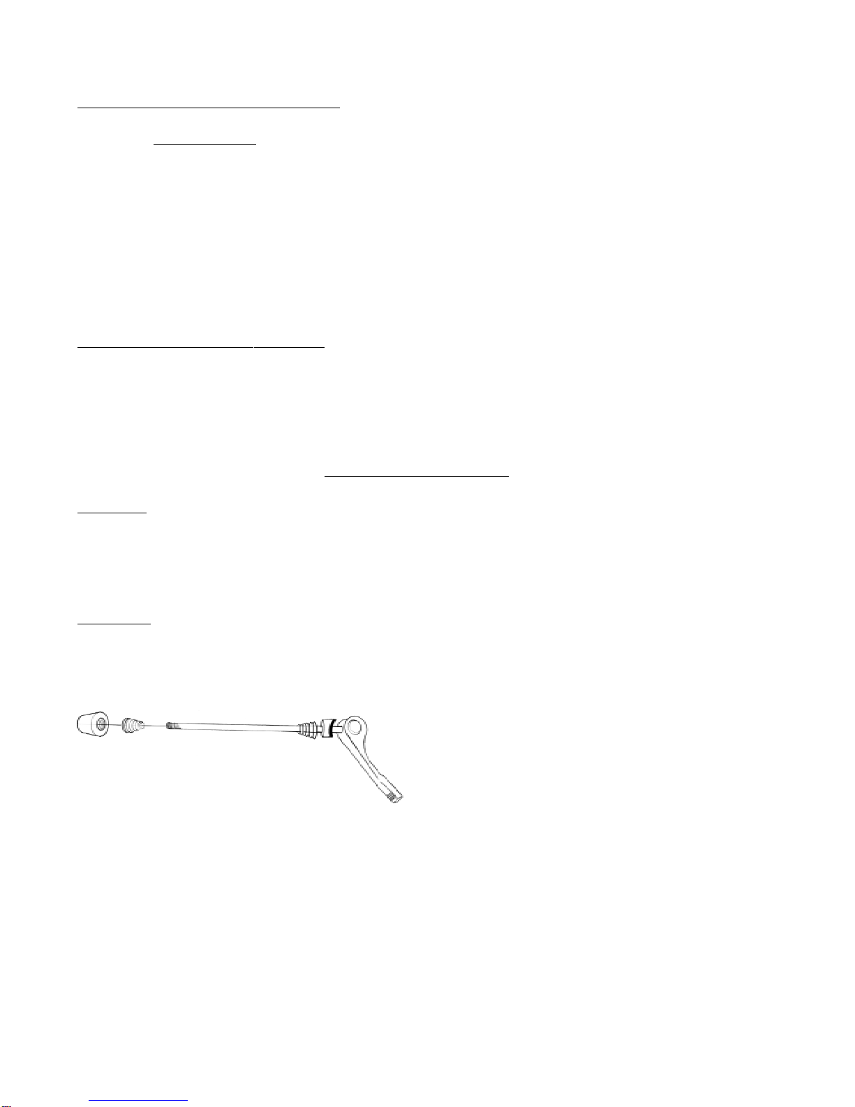
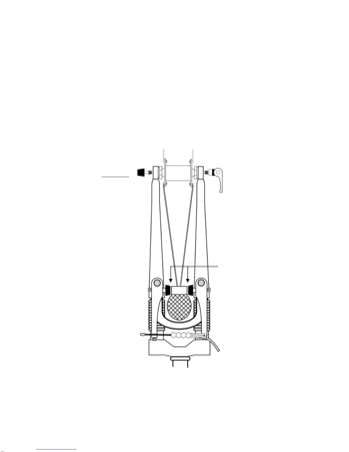
Tension Adjusting Nut Spring Spring
Lever
FIG. 13
STEP 11: FRONT WHEEL QUICK RELEASE
In this step you will secure the Front Wheel using the Front Wheel Quick Release.
IMPORTANT: Before doing this, read the following as a thorough understanding of the Front
Wheel Quick Release system is necessary for proper operation and safety.
While it may look like a long bolt with a simple lever and nut on the ends, the Front Wheel Quick
Release uses an adjustable Lever and Cam on a skewer to secure the bike’s Front Wheel to the Fork.
Due to its Quick Release action and adjustable nature it is critical that you understand how the Quick
Release lever and cam work to insure your safety by proper usage.
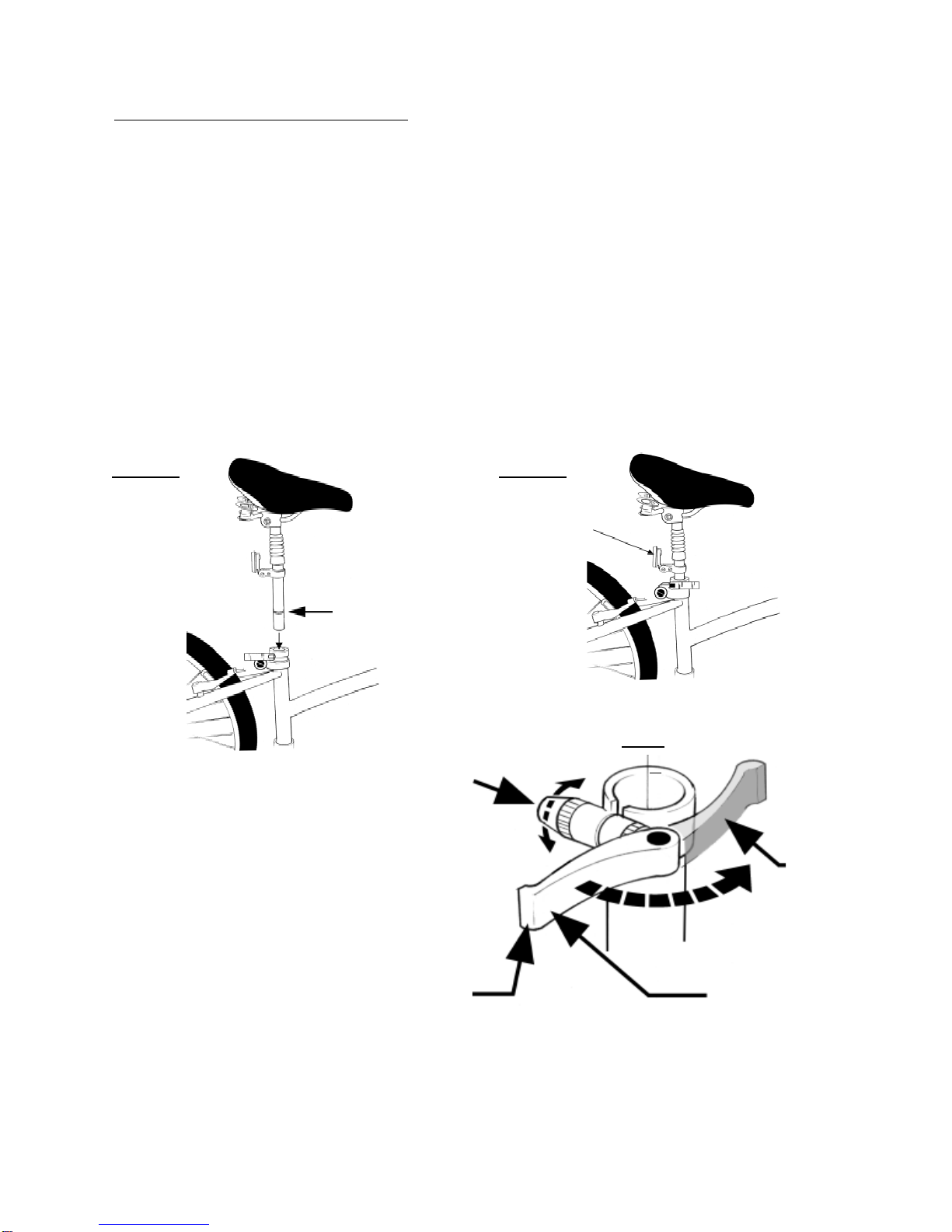
The Front Wheel Quick Release Lever allows for both an open (release) position and a closed (secure)
position. When tightly closed, the Wheel Hub and Assembly are securely clamped to the Fork by the
action of the Front Wheel Quick Release Lever and Cam. When open, the Wheel Hub and Assembly
are no longer securely clamped to the Fork thus allowing the Wheel to easily come off the Fork. It is
critical for your safety, that the Front Wheel Quick Release Lever be tightly closed when riding.
The amount of clamping force is controlled by the Tension Adjusting Nut. Turning the Tension Adjusting
Nut clockwise while keeping the Lever from rotating increases clamping force; turning it counter
clockwise while keeping the Lever from rotating reduces clamping force. Less than half a turn of the
Tension Adjusting Nut can make the difference between safe clamping force and unsafe clamping force.
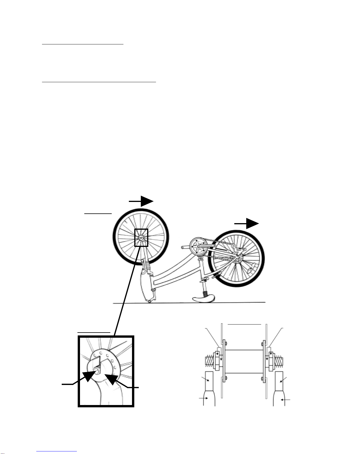
A) Now take the Front Wheel Quick Release and remove the Tension Adjusting Nut and one
Spring and slide the Front Wheel Quick Release Skewer through the Wheel Hub from the chain
side and replace the Spring and Tension Adjusting Nut so that the wide section of the Spring is
against the Tension Adjusting Nut. Important make sure the Lever is located in the round portion of
the cam bushing as shown in FIG. 14A.
IMPORTANT: The following 2 figures (15 & 16) show the Front Wheel Fork as if you had
turned the bike over as recommended in Step 9 FIG 12.
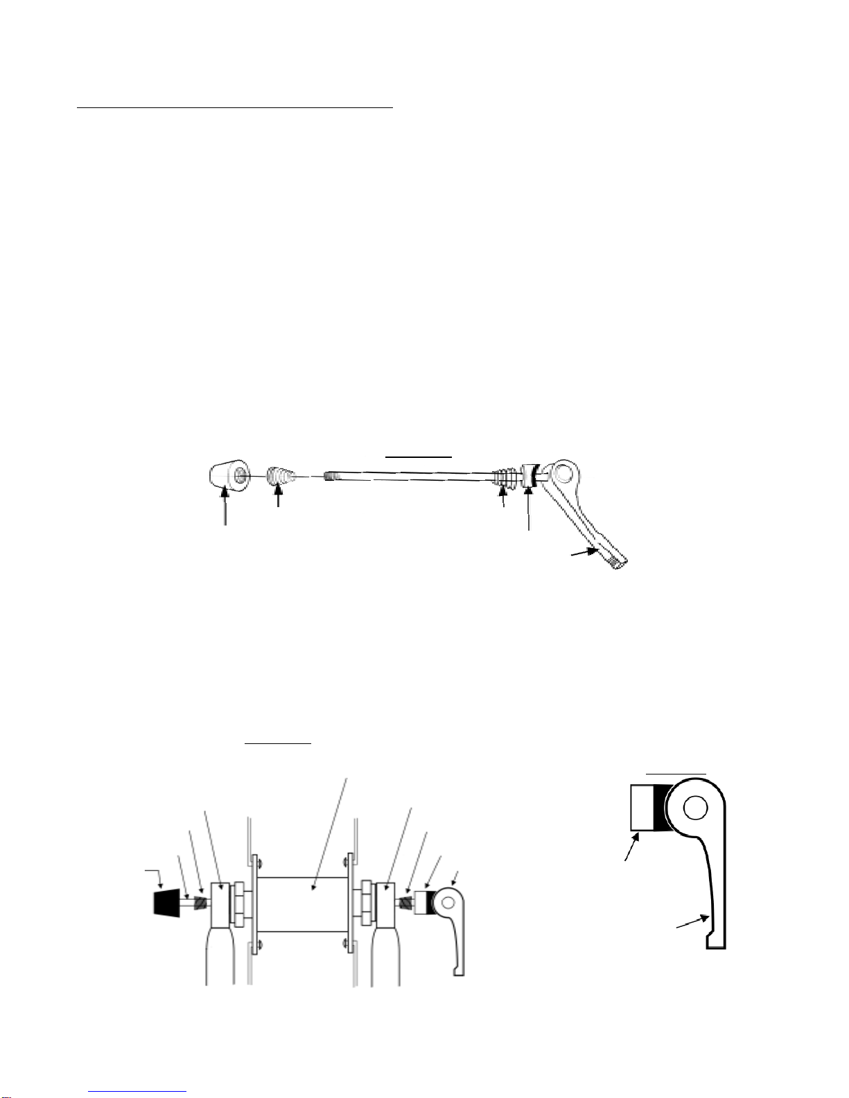
FIG. 14
I
Lever Cam
FIG. 14A
Lever
Lever Cam
8
Skewer
Spring
Wheel Assembly
Fork Dropout
Tension
Adjusting
Nut
Lever
Fork Dropout
Lever Cam
Spring

9
B) Holding the Quick Release Lever in the open position with your right hand tighten the Tension
Adjusting Nut with your left hand until it is finger tight against the Fork Dropout.(See FIG. 14)
C) Before closing the Quick Release Lever in Step D) Fig. 16 stand in front of and hold the Front
Wheel with your left hand. Now look down and center the Front Wheel between the Front Brake
Pads so that there is an equal gap of about 1mm between the Brake Pads and Wheel Rim.
Now close the Quick Release in as shown in FIG 16, Page 10 while holding the wheel steady. The
wheel could pull to one side during Quick Release clamping.
Once completed do a visual inspection and spin the Front Wheel to ensure the wheel is centered
between the Fork and there is an equal gap between Brake Pads and Rim. If not centered or
rotating freely release the Quick Release and repeat.
FIG. 15
Note: Assumes bike is
upsidedownfor assembly
perinstructionsandlooking
fromthefrontof the bike.
Look here
NOTE: If after centering the Wheel the Brake Pads are still not even the Brakes may need fine
tuning. See Owner’ s Manual.

10
D) Move the Quick Release Lever downwards and push it into the closed position.
The Lever should be parallel to the Fork Blade and curved towards the Wheel.
IMPORTANT: If you can fully close the Quick Release without wrapping your fingers around
the fork blade for leverage, and the Lever does not leave a clear imprint in the palm of your
hand, the tension is insufficient. Open the Lever; turn the Tension Adjusting Nut clockwise
a quarter turn; then try again. If the Lever cannot be pushed all the way to a position
parallel to the fork leg, return the Lever to the OPEN position. Then turn the Tension
Adjusting Nut counterclockwise one-quarter turn and try tightening the Lever again.
WARNING: The full force of the Lever and cam action is needed to clamp the Wheel
securely to the Fork. THE LEVER MUST BE CLOSED AND LOCKED WITH THE FORCE
TO SECURE THE WHEEL SAFELY IN THE FORK DROPOUTS BEFORE RIDING. JUST
TURNING THE TENSION ADJUSTING NUT IS NOT SUFFICIENT. THE LEVER MUST BE
CLOSED.
Closed
Open
Tension
Adjusting
Nut
FIG. 16
Fork
Fork Dropout

S
TEP 12: RETURN BIKE TO UPRIGHT POSITION
Return the LandRider to its upright position if you turned it upside down. Place the Kickstand
down to allow the bike to stand on its own. (See FIG. 17).
STEP 13: CONNECTING PEDALS
IMPORTANT
Please follow connecting Pedal instructions carefully.The Alloy Crank Arm can be damaged if
the Pedal Nut Thresd is not inserted correctly.Gently insert Pedal Nut Thread into Crank Arm hole
and try to turn carefully to get thread started.
There is a Right Pedal marked “R” and a Left Pedal marked “L” (The Pedal marked “R” has right hand
threads and the Left Pedal “L” has left hand threads). If it is a little tricky to get the Pedal Nut Thread started in
theCrankArm, bepatient andtryand keepthe Pedalstraight.
A) Place the Right Pedal into the Right Crank Arm which is the same side as the Chain. Use your fingers to get
started and gently turn thePedal Nut in aclockwise direction. Using the 15mmwrench provided, firmlytighten
thePedalNut.
B) Placethe LeftPedal into theLeft CrankArm andusing your fingers,gently turnthe PedalNut in a
counterclockwise direction to get started. Using the 15mm Wrench provided firmly tighten the Pedal Nut. Be
careful not to switch Right and Left Pedals. Right Pedal is only for right and Left is only for left. Make
surethe threads of eachPedal are fullyin the Crank Armand tighten firmly.
Kick Stand
FIG. 17
Right Pedal
Left Pedal
Pedal Nut
Crank Arm 11

12
STEP 14: RECONNECTING FRONT BRAKE
Reconnect Front Brake by squeezing the two Brake Arms together with your right hand. Using
your left hand, place the Cable Sleeve end through the Swinging Brace on the Left Brake Arm.
REFER TO THE OWNER’s MANUAL IF YOU HAVE ANY PROBLEMS AND TO CHECK AND SET THE
BRAKES.
FIG. 20 Closed
Left
Brake
Arm
FIG. 19
Swinging
Brace
FIG. 18 Open
Cable
Sleeve
Cable
Sleeve
Squeeze Squeeze

To check for correct Seat height:
A) Sit on the Seat
B) Place one heel on a Pedal
C) Rotate the Crank until the Pedal with your heel on it is in the down position and the Crank Arm
vertical. (See FIG. 21 below).
If your leg is not completely straight and is just touching the center of the Pedal, your Seat height
needs to be adjusted. See Step 6 of these Assembly Instructions for adjusting the Seat Post Quick
Release.
The Seat angle on the Seat Post has been factory set. Refer to the Owner’ s Manual for
Seat angle adjustment.
STEP 15: ADJUSTING SEAT HEIGHT
Adjust the Seat Post to the correct height for you. Your leg length determines the correct Seat and
Seat Post height.
FIG. 21
WARNING: Refer to the Owner’ s Manual and check that you have 1” clearance
between the Top Tube and your crotch.
WARNING: Make sure Quick Release Lever is closed and Seat Post is secure before
riding. Do not raise Seat Post above Minimum Insertion Line. (See Step 6, FIG. 6 & 8).
13

14
STEP 16: HANDLEBAR ADJUSTMENTS
Now it is time to adjust the handlebar. First study FIG. 22 so you have a good understanding of the
Handlebar.
Stem Bolt Plug
FIG. 22
Stem Bolt
(raises and
lowers Stem
in the
Head Tube)
Stem
Minimum Insertion Line
Stem Cone
Tilt Arm
Handlebar
Bracket
Head Tube
Stem Bolt End
Handlebar Tilt Arm
(changes height of Handlebar
and brings Handlebar closer or
further away from rider)
Handlebar
Bracket Bolts
(changes tilt of Handlebar)
A) Check cables are not tangled. See Step 5 D (FIG. 4 & 5 on page 4)

YES NO!
FIG. 24 FIG. 25
B) Remove Stem Bolt Plug. Using largest Allen Key loosen 6mm Stem Bolt (See FIG. 23) and
raise Stem up to 3.5 inches depending on your height. Do not raise Stem above Minimum Insertion
Line. Check Handlebar is straight (See FIG. 24 & 25) and firmly tighten clockwise Stem Bolt
FIG. 23 Stem Bolt Plug
Minimum Insertion Line
3.75” Maximumrange ofstemheight
15

16
C) Loosen the 6mm Tilt Arm Bolt under the Tilt Arm. Now raise the Tilt Arm to 40° mark which is
our general recommendation. Firmly tighten Tilt Arm Bolt.
FIG. 26 FIG. 27
D) The Handlebars should be in the correct position for riding so that the Grip is approximately 1.5
inches above the Brake Handles. (See FIG. 28).If not or you prefer a different angle loosen the
two 5 or 6mm Handlebar Bracket Bolts and tilt the Handlebars to the correct angle and firmly tighten
Handlebar Bracket Bolts. (See FIG. 27).
FIG. 28
1.5”
FIG. 29
E) Now sit on the Seat and place hands on the Handlebars and grasp the Brakes and make
sure you can comfortably reach and operate the Brakes. If adjustment is necessary repeat step
16 C, B, C, and D in that order (you will need to lower Tilt Arm to 0° to be able to reach Stem Bolt).
WARNING: Firmly tighten all Bolts before continuing.
Tilt Arm
Handlebar
Bracket Bolts
Tilt Arm Bolt

WARNING: Make sure the Fender does not block clear view of rear Reflector.
STEP 17: ADJUSTING FENDER
A) Adjust the Fender height by loosening the Fender Bolt using the Philips Head Screwdriver. We
recommend Fender follows angle of the Wheel and approximately 2” above Tire. Tighten Fender
Bolt.
FIG. 30
Fender Bolt
Bracket Bolt
Nut
Fender
Seat Tube
Bracket Insert
Seat Post Quick Release
B) If necessary adjust the Fender side angle by first loosening the Bracket Bolt and then tightening,
using the Philips head screwdriver.
Fender Bracket
17

STEP 18: REMOVING PROTECTIVE SHIPPING MATERIAL
Carefully remove the remaining protective cardboard paper from the Frame and Fork.
18
CONGRATULATIONS you have assembled your LandRider.
IT IS VERY IMPORTANT THAT YOU REVIEW THE FOLLOWING:
1. Your LandRider has been shipped with lower than normal Tire air pressure due to temperature
fluctuations during shipping. Please inflate according to directions in Manual (See Tire and
Tubes).
2. The LandRider has a total of 14 Automatic gears. There are 7 for the flat (high) and 7 for the hills
(low). To change between high and low you shift the Shifter on the left Handlebar Grip which
changes the Front Derailleur (where the Pedals are). The Front Derailleur AutoMax Shifter has been
factory set in the low position. Most people ride the LandRider in high using low for hills. When you
take your first ride we recommend you engage high gear (See Page 15 and Front Derailleur in
the Manual)
.
IMPORTANT: You must be pedaling forward to change between high and low or vice versa.
3. Every LandRider is thoroughly inspected and brakes are pre set however minor adjustments may
be necessary. Please review page 9 of these Assembly instructions if Brake Pads are rubbing or
Brakes are not functioning correctly or see Brakes section in the Manual.
4. Please review Owner’ s manual thoroughly before riding.
If you have any problems, contact LandRider at 1-800-945-5335 or email us at
service@landrider.com
or review troubleshooting guide of Owner’s Manual.

Venture Cycle, LLC
2328 West Joppa Road,
Suite 100
Lutherville, MD 21093
Table of contents