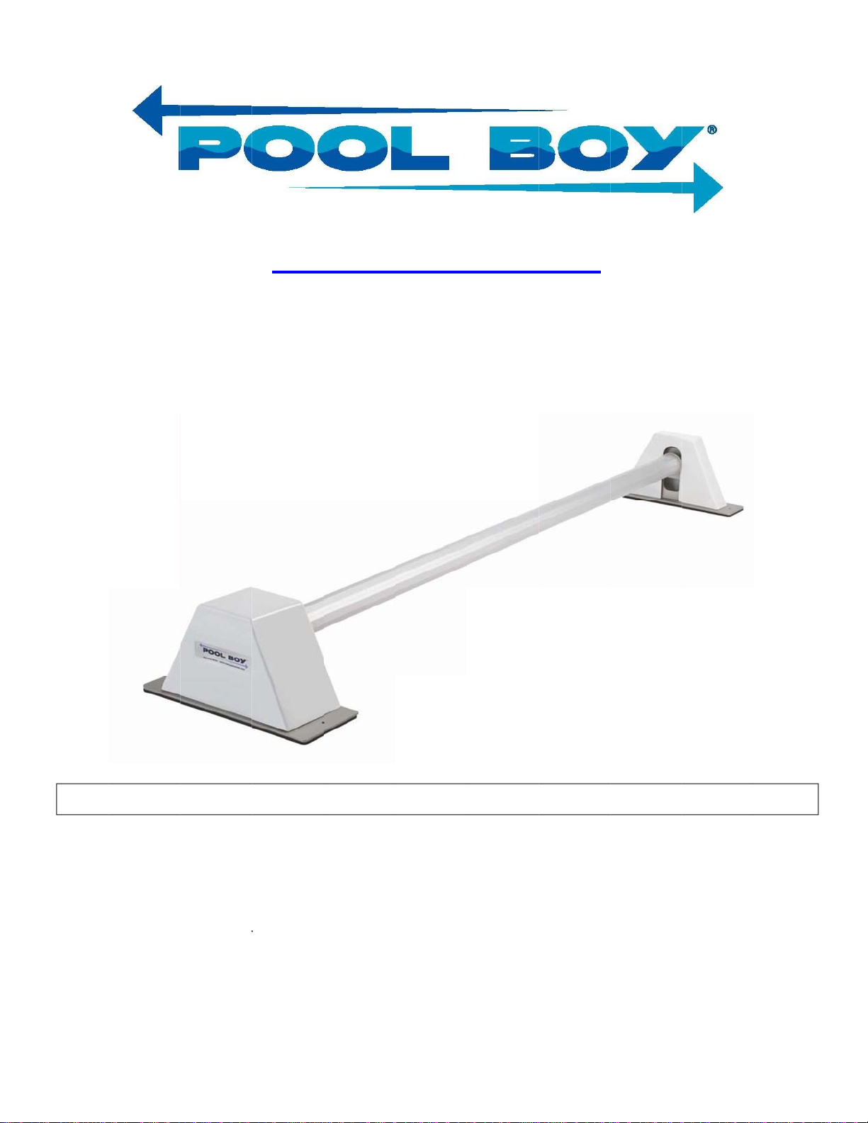
4) Test Run
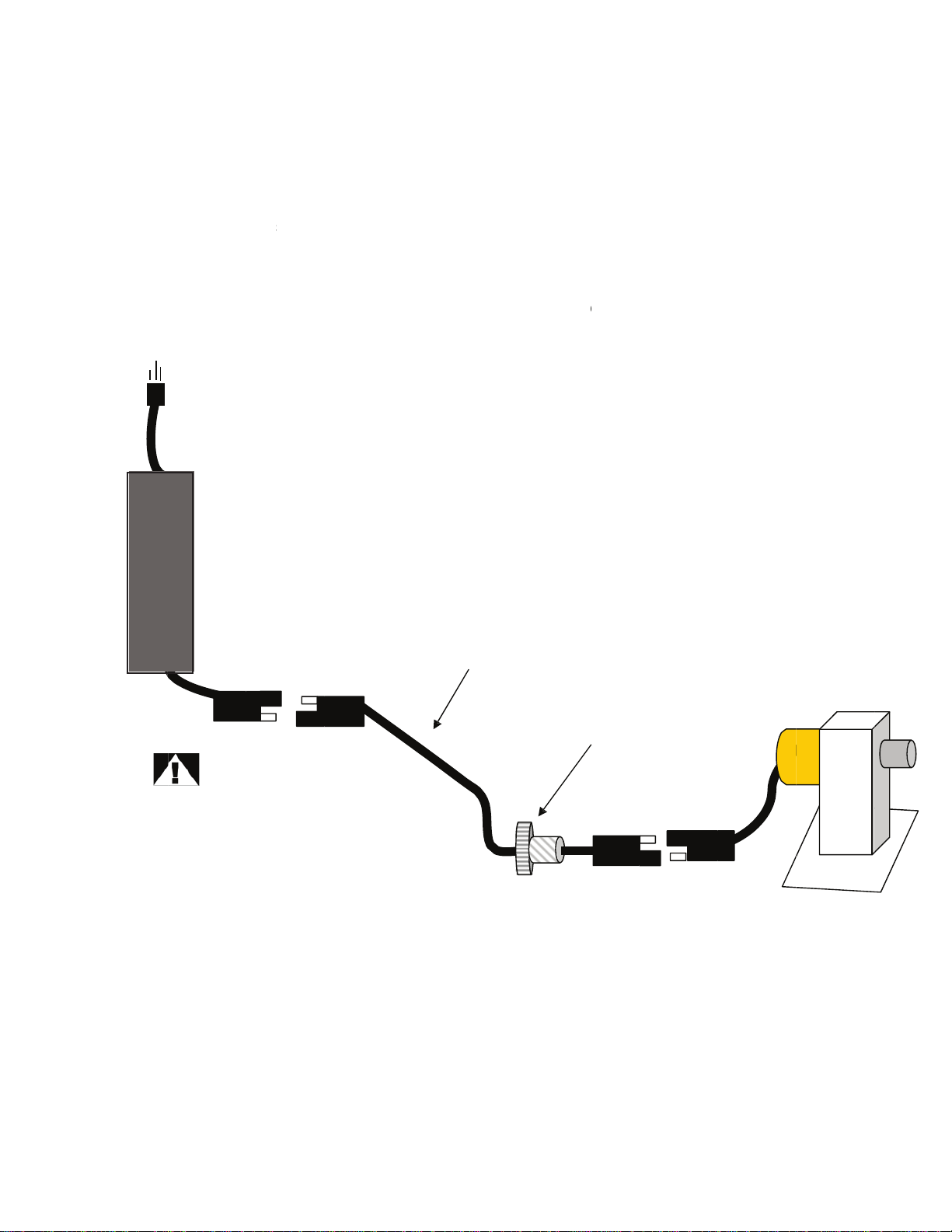
Plug the power supply into a GFI equipped receptacle. With the crosstubes attached, test run the system. (See
the OPERATION Section for instructions.) Ensure the cross tube is securely attached to the Pool Boy® hubs and
that it runs smoothly without wobble.
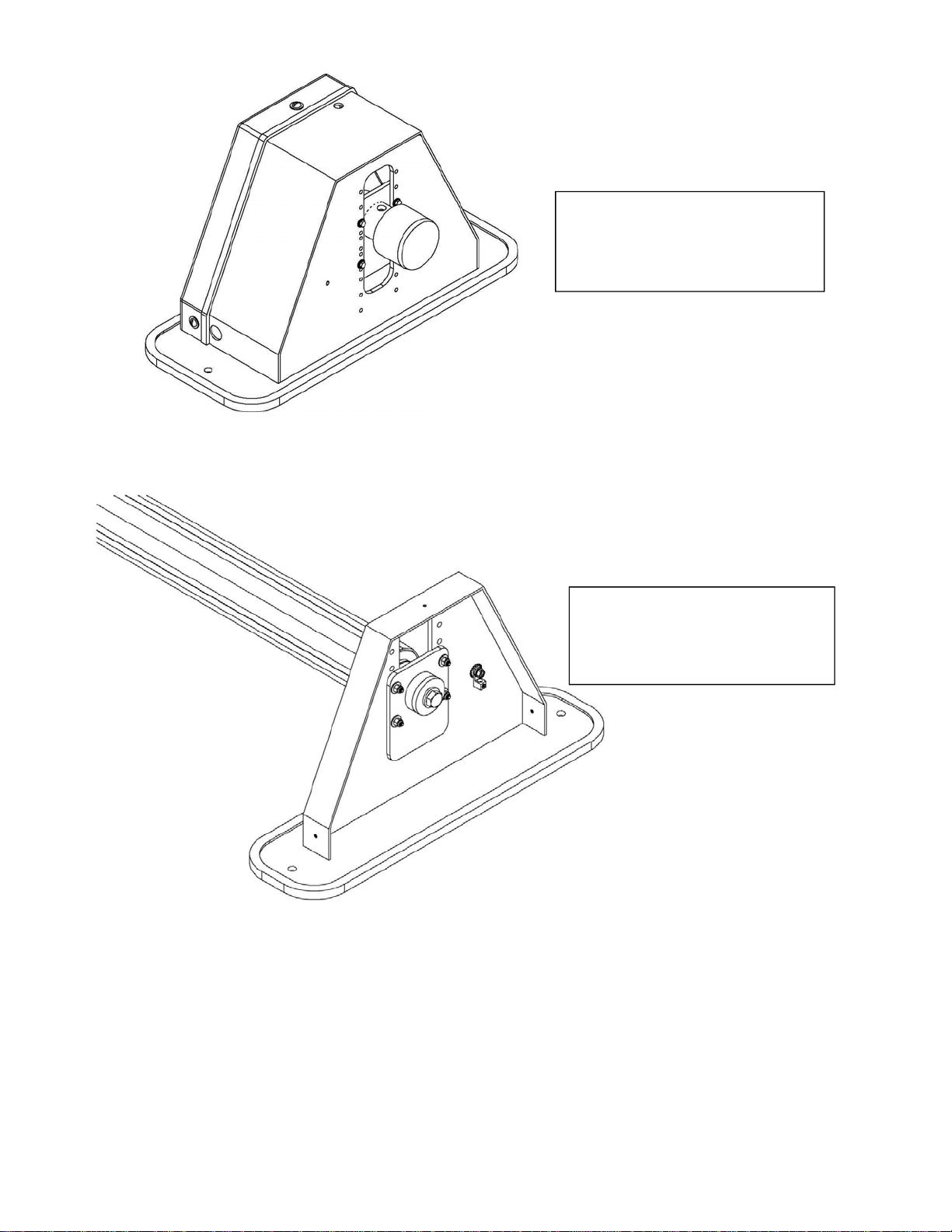
5) Install the covers for the drive and idler stands
Install the drive stand cover. Make sure the motor harnessis routed through the slot in the side of the cover. If the
idler stand cover was removed, reinstall it at this time.
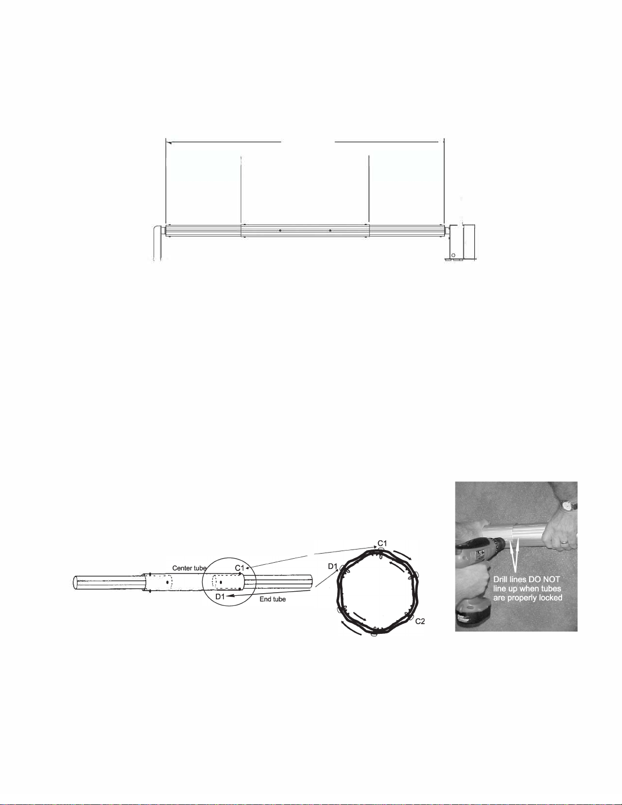
6) Attach the Solar Blanket
Attach the solar blanket onto the cross tube in the manner prescribed by the blanket/blanket strap manufacturer.
Consult your solar blanket retailer for details. The blanket can wind onto the cross tube either direction.
7) Install tether kit
The tether kit attaches to the leading edge of the solar cover, opposite the end that wraps onto the cross tube. The
tether kit is used to guide the cover during extension and retraction.
1.
Carefully wrap the edge of the cover around the rods (2) 5ft pieces. Ensure the wrap is even and square to
the leading edge and center of the cover.
2.
Install the supplied (5) clips as shown in the following diagram. Bolt through the cover material, a hole will
need to be made thru the blanket. Install clamps evenly, approximately one every two feet.
3.
Snap the guide rope harness to the clamps as shown.
1. CONNECTING THE SOLAR COVER TO THE
REEL
(Refer to Step #1)
1. Select a location suitable for pool cover removal, usually
on the pool end without steps. Make sure teh Solar Cover
is trimmed properly. The tube should be positioned perpen-
dicular to teh center line of the pool as in Step #1. PROPER
ALIGNMENT BETWEEN POOL COVER AND THE TUBE IS
CRITICAL! Whether your pool is rectangular or irregular in
shape, the straps must be placed and installed so that there is
equal pull on all straps at the same time to help prevent mis-
alignment of the cover.
2. ATTACH COVER PLATES TO SOLAR
BLANKET
(Refer to Step #2)
1. Starting at one side of the solar cover, position a set of
cover plates (male and female) with the large center slot at the
location of the blue strap and at least 2” from any edge of the
cover.
2. With a sharp instrument, using the female plate as a guide
and with the raised ridges facing DOWNWARD, punch 3 holes
through the cover plate and cover. The holes must be as wide
as the holes in the plate.
3. Place a male plate under the cover directly beneath the
female plate.
4. Insert the 2 snaps through the cover and snap together. If
the plates do not snap into position with normal force, remove
excess cover material.
5. Repeat this operation until all the plates have been in-
stalled on the cover.
3. ATTACH STRAP / STRAP BUCKLE
(Refer to Steps #3, #4, and #5)
1. With the ribbed crossbar on the strap buckle facing up,
slide the buckle onto the strap from the end opposite the vel-
cro.
2. Position the buckle at least 24” from the strap end. Brin
ghte strap underneath the solar cover and up through the cen-
ter opening in the plate.
3. Thread the strap end back through the buckle.
4. Repeat process for each strap.
STEP #1
STEP #3
STEP #4
STEP #5
4) Test Run
Plug the power supply into a GFI equipped receptacle. With the cross tubes attached, test run the system. (See
the OPERATION Section for instructions.) Ensure the cross tube is securely attached to the Pool Boy® hubs and
that it runs smoothly without wobble.
5) Install the covers for the drive and idler stands
Install the drive stand cover. Make sure the motor harness is routed through the slot in the side of the cover. If the
idler stand cover was removed, reinstall it at this time.
6) Attach the solar blanket
Attach the solar blanket onto the cross tube in the manner prescribed by the blanket/blanket strap manufacturer.
Consult your solar blanket retailer for details. The blanket can wind onto the cross tube either direction.
7) Install tether kit
The tether kit attaches to the leading edge of the solar cover, opposite the end that wraps onto the cross tube. The
tether kit is used to guide the cover during extension and retraction.
1.
Carefully wrap the edge of the cover around the rods (2) 5ft pieces. Ensure the wrap is even and square to
the leading edge and center of the cover.
2.
Install the supplied (5) clips as shown in the following diagram. Bolt through the cover material, a hole will
need to be made thru the blanket. Install clamps evenly, approximately one every two feet.
3.
Snap the guide rope harness to the clamps as shown.
1. CONNECTING THE SOLAR COVER TO THE REEL
(Refer to Step #1)
1. Select a location suitable for pool cover removal, usually
on the pool end without steps. Make sure teh Solar Cover is
trimmed properly. e tube should be positioned perpen-
dicular to teh center line of the pool as in Step #1. PROPER
ALIGNMENT BETWEEN POOL COVER AND THE TUBE
IS CRITICAL! Whether your pool is rectangular or irregular
in shape, the straps must be placed and installed so that there
is equal pull on all straps at the same time to help prevent
misalignment of the cover.
2. ATTACH COVER PLATES TO SOLAR BLANKET
(Refer to Step #2)
1. Starting at one side of the solar cover, position a set of
cover plates (male and female) with the large center slot at the
location of the blue strap and at least 2” from any edge of the
cover.
2. With a sharp instrument, using the female plate as a guide
and with the raised ridges facing DOWNWARD, punch 3
holes through the cover plate and cover. e holes must be as
wide as the holes in the plate.
3. Place a male plate under the cover directly beneath the
female plate.
4. Insert the 2 snaps through the cover and snap together. If
the plates do not snap into position with normal force, remove
excess cover material.
5. Repeat this operation until all the plates have been in-
stalled on the cover.
3. ATTACH STRAP / STRAP BUCKLE
(Refer to Steps #3, #4, and #5)
1. With the ribbed crossbar on the strap buckle facing up,
slide the buckle onto the strap from the end opposite the
velcro.
2. Position the buckle at least 24” from the strap end. Brin
ghte strap underneath the solar cover and up through the
center opening in the plate.
3. read the strap end back through the buckle.
4. Repeat process for each strap.
4. ATTACH VELCRO HOOK TO ALUMINUM TUBE
(Refer to Step #6)
1. Place the velcro end of the strap over the tube.
2. Standing behind the tube, pull the strap taut and align as
straight as possible between the cover plate and the tube.
3. Remove adhesive backing from the velcro tab and place it
rmly into position at the top of the tube. Tube must be dry
and free from grease or dirt.
4. Repeat procedure for each strap keeping the velcro adhe-
sive tape in a line along the top of the tube.
5. Use the buckles to adjust each strap so all straps provide
equal tension on the solar cover when rolling the solar cover
onto the reel.
STEP #1
STEP #2
STEP #3
STEP #4
10
4) Test Run
Plug the power supply into a GFI equipped receptacle. With the cross tubes attached, test run the system. (See
the OPERATION Section for instructions.) Ensure the cross tube is securely attached to the Pool Boy® hubs and
that it runs smoothly without wobble.
5) Install the covers for the drive and idler stands
Install the drive stand cover. Make sure the motor harness is routed through the slot in the side of the cover. If the
idler stand cover was removed, reinstall it at this time.
6) Attach the solar blanket
Attach the solar blanket onto the cross tube in the manner prescribed by the blanket/blanket strap manufacturer.
Consult your solar blanket retailer for details. The blanket can wind onto the cross tube either direction.
7) Install tether kit
The tether kit attaches to the leading edge of the solar cover, opposite the end that wraps onto the cross tube. The
tether kit is used to guide the cover during extension and retraction.
1.
Carefully wrap the edge of the cover around the rods (2) 5ft pieces. Ensure the wrap is even and square to
the leading edge and center of the cover.
2.
Install the supplied (5) clips as shown in the following diagram. Bolt through the cover material, a hole will
need to be made thru the blanket. Install clamps evenly, approximately one every two feet.
3.
Snap the guide rope harness to the clamps as shown.
STEP #2
10