POOL Latham User manual

L0311 Rev 3 6-21 © Latham Pool Products, Inc. 2021. All rights reserved. Page 1 of 9
Touch Screen Pool Cover Controller Wiring and
Installation Instructions
Table of Contents
Important Safety Instrucons ....................................................................................................................1
Installaon Notes .......................................................................................................................................1
Product Summary ......................................................................................................................................2
Mounng Instrucons................................................................................................................................2
Wiring Descripon .....................................................................................................................................3
Standard Setup Procedure.........................................................................................................................4
Accessing the Setup Menu..................................................................................................................4
Set a Primary Controller......................................................................................................................4
Congure Devices ...............................................................................................................................4
Verify Connecons and Lock Network................................................................................................5
Assign Main Device .............................................................................................................................5
Calibrate each device..........................................................................................................................5
Set Passwords .....................................................................................................................................5
Edit Service Screen..............................................................................................................................5
User Sengs .......................................................................................................................................6
Wi-Fi Setup..........................................................................................................................................6
Menu Structure..........................................................................................................................................7
Mesh Conguraon Opons ........................................................................................................... 9
WARNING! IMPORTANT SAFETY INSTRUCTIONS
READ AND FOLLOW ALL INSTRUCTIONS
Warning: To avoid re or electrocuon.
Idenfy GFCI breaker at distribuon panel and turn o power before aempng to service or install equipment.
Only install the touch controller to a single gang box rated for outdoor use.
Make motor connecons in an all-weather juncon box as high as possible in the cover box.
Install this device in accordance with naonal and local electrical codes (NEC 680-26).
Electrical wiring and service work should only be performed by a qualied individual.
Warning: To avoid injury or drowning.
The control switch must be mounted in a xed locaon where 100% of the pool surface is visible.
Installation Notes
Use water ght connecons at all wire juncon locaons.
Install device in locaon where exposure to sun and water sources (e.g. sprinklers, water downspouts) are limited.
Make sure all gaskets are undamaged and are clean and free of dirt and debris.
To reverse motor spin direcons, see the “Congure Devices” secon in “Standard Setup Procedure.”
The power circuit should be sized for 15 amps and must be sized accordingly.
Perform a pool calibraon on touch pad aer installaon for accurate current limits and operaonal cycle counts.
Wi-Fi features require a Wi-Fi network to be present and associated to the device to receive alerts.
Keep remote devices in line of sight of controlling devices for best performance.
⚠

L0311 Rev 3 6-21 © Latham Pool Products, Inc. 2021. All rights reserved. Page 2 of 9
Touch Controller Operaon:
This device unlocks by entering a 4 number passcode congured by
the installer or user. The touch controller can operate covers directly
through high voltage power, indirectly via a control board (low
power), or wirelessly through another touch controller. The device
will stop the motor if 1) The operaon buon is released 2) Motor
current exceeds the set limit or 3) A limit switch is triggered (with
control board).
If motor current is exceeded, the buon for the direcon operated will turn red and the cover will stop. Aer the buon is
released, the cover can be operated in either direcon.
If the limit switch is triggered, movement in that direcon will be disabled unl the cover is operated in the opposite direcon.
With 121 control boards, the buon in the tripped limit direcon will disappear unl the cover is ran in the opposite direcon.
With the high voltage limit board the cover will stop, but the touch controller will display as if it’s operang.
Product Summary:
The touch screen pool cover controller is designed to operate all of
Latham’s 3 wire motor oerings either directly or through a control
board. It is compable with the 121 Motor Controls and the 3 Wire
Limit control board assemblies. It also has built in Latham mesh
capability to support wireless communicaon with mulple touch
pads. In addion, the product has support for Wi-Fi nocaons
which can nofy via text or email when your cover is operated.
Product Applicaons:
Electric 3 Wire motor oerings
Hydraulic systems (with compable control board)
Switch upgrades for premium features
Torque sensive applicaons (Prevent rope breakage/
system damage)
Mulple control locaons without addional wiring
Mulple covers controlled from a touch pad
Key Features:
Touch screen with simplied operaon and setup
Mesh network to wirelessly communicate with up to 4
touch controllers
Current liming with setup wizard
Wi-Fi nocaons when cover is operated or le open.
4 users with unique passcodes
Zero power motor acvaon and deacvaon
Mounng instrucons:
1) Aach M1146 adapter plate to juncon box using
provided hardware.
2) Connect wiring according to schemac.
3) Carefully feed connected wires into juncon box and secure
the E1146 touch controller to the M1146 adapter plate.
4) Aach M1147 lid to E1146 controller
using 2 supplied hinge screws.
Marked
A
Marked
B
Marked
B
M1146
E1146
M1147

L0311 Rev 3 6-21 © Latham Pool Products, Inc. 2021. All rights reserved. Page 3 of 9
High voltage wiring
Color
#1 Input Power Neutral White
#2 Input Power Line/Hot Black
#3 Earth Ground Green
#4 Motor Direction 2 Black
#5 Motor Neutral White
#6 Motor Direction 1 Red
#3
#4
#5
#6
#2
#1 Low voltage wiring
Color
5v DC+ Red
Gnd DC- Black
Control board Rx White
Control board Tx Green
Wiring Description:
System Diagram and Configuration Options:
Connect AC leads,
Cap Motor leads
To Breaker Panel
Opon 1: Remote Opon 2: High Voltage Motor
To Breaker Panel
Connect AC leads,
Match motor wiring,
Connect all grounds
#2
#1
#3
#6
#5
#4
AC
Leads
AC
Leads
Motor
Leads
#2
#1
#3
#6
#5
#4

L0311 Rev 3 6-21 © Latham Pool Products, Inc. 2021. All rights reserved. Page 4 of 9
System Diagram and Configuration Options:
Opon 3: High Voltage Control Board
To Breaker Panel
Connect AC leads,
Match HV wiring and connect grounds
To Breaker Panel
Red
Quick
Connect
(Internal)
Opon 4: Low Voltage Control Board
Match low voltage wires from
control board
Electric Motor or
Hydraulic Power Pack
Standard Setup Procedure:
Accessing the Setup Menu:
1. Enter a 4 digit passcode (Maintenance Passcode 5991— Default User 1 Passcode 1234).
2. Select the Setup Icon in the bottom left corner.
Set a Primary Controller:
1. Select a controller to set as Primary.
- If only one touch controller is used in the system it should be set as the Primary.
- If multiple controllers are in the system, select the controller which is closest to the internet router.
2. Access the Setup Menu using the steps above.
3. Select Maintenance.
4. Select Force Primary to set the device as a Primary.
- If Force Secondary is displayed the device is already configured as a primary.
5. The controller will reboot and a Wi-Fi icon will be displayed in the top left corner.
Configure Devices:
1. Access the Setup Menu
2. Select Device Setup to enter the Device Setup Menu.
3. Select Device Setup to select a device to configure.
#2
#1
#3
#6
#5
#4
AC
Leads
Control
Leads
121
Keypad
Leads

L0311 Rev 3 6-21 © Latham Pool Products, Inc. 2021. All rights reserved. Page 5 of 9
Standard Setup Procedure (cont.):
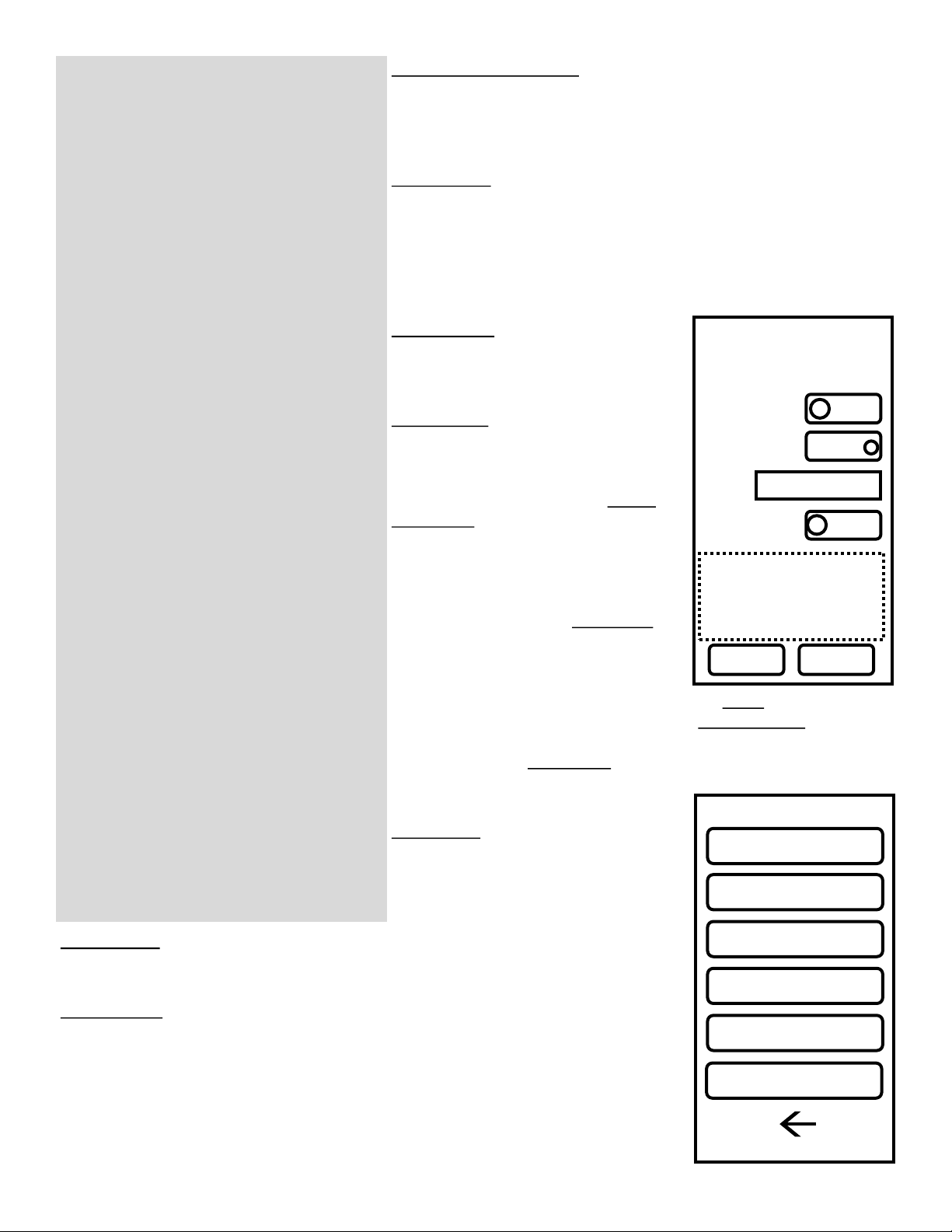
4. Select the top Node listed to configure the device you’re operating.
Enable Connection: If the device is wired to a pool cover through a motor or motor control board select enabled.
If the device is only wired to power and is remotely controlling another device, select “disabled.”
Connection Type: Select to “on” if this is hooked up low voltage to a motor control board. For any other case
set to “off.”
Name: Enter a name that represents the device. This will show up throughout the user interface and is how this
will be selected on other devices.
Cover Direction: Assigns the Open/Close buttons to a cover direction. If the device operates in reverse from
what the buttons list, change the direction from “cw” to “ccw.”
Limit Direction: Assigns which magnet side will stop a cover for the open and close directions. If the limit is stop
ping the cover in the wrong direction, change the limit from “open” to “close”
5. When finished, select Done to exit Device Setup. The Controller will reboot within the next few seconds to apply the
settings.
Verify Connections and Lock Network:
1. After configuring a Primary device, all touch controllers should automatically connect themselves. Touch controllers
ship by default in an unlocked state to aid in installation.
2. Verify all desired controllers are wirelessly connected by logging into one and verifying the “Another keypad is cur-
rently active..” message is displayed on the others. Verify the configured devices are also listed on either the “Select
Cover” or “Other Covers” list.
3. Log into the primary device with the Maintenance Passcode and access the Setup Menu.
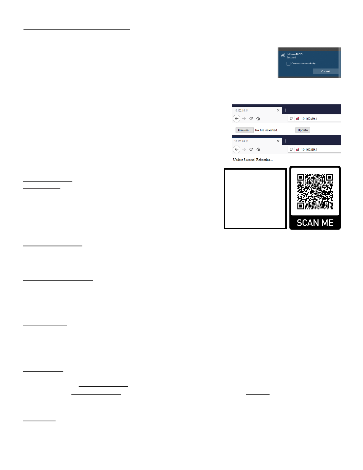
4. Select WiFI Setup then select Lock Network to keep the current devices assigned to this network and prevent other
devices in the area from connecting. If a network is not locked the system will automatically lock the network after 2
hours.
Assign Main Device:
1. For each device, log in using the Maintenance Passcode and navigate to the Setup menu.
2. Enter the Device Setup Menu.
3. Select Assign Main, then select the device to set as the Main cover.
4. The Main cover will be displayed on the large button in the Select cover screen.
Calibrate each device:
1. For every device with a connection enabled, go through the pool calibration process below.
2. Log in with Maintenance Passcode and access the Setup Menu.
3. Select Maintenance then select Calibrate Pool to display a list of covers.
4. Select the desired cover to start the calibration wizard.
5. Follow the on screen instructions stopping just before the cover is fully open or closed. Operating the cover into a
physical stop can affect both calibration time and calibration current which leads to incorrect settings.
6. After Calibration a summary will display. If the values are acceptable select confirm to save settings. If there was in
issue with calibration select Recalibrate to restart the wizard.
Set Passwords:
1. Log in as User 1 (1234 by default) and navigate to the Setup Menu.
2. Select Set Passwords to display the screen to Edit Passcodes.
3. Tap on the username to edit the name for each desired user.
4. Tap on each passcode number to edit the passcode.
5. The field that’s selected for editing will have a box around it.
6. Select Save when all usernames and passwords are as desired.
7. Setting users and passcodes will update settings for all devices connected to that network.
8. User 1 will have access to modify all usernames and passcodes. Users 2 - 4 will only be able to set their own cre-
dentials.
Edit Service Screen
1. Log into the device using the Maintenance Passcode and navigate to the Setup Menu.
2. Select Maintenance then select Edit Service Screen.

L0311 Rev 3 6-21 © Latham Pool Products, Inc. 2021. All rights reserved. Page 6 of 9
Standard Setup Procedure (cont.):
3. Tap under Company Name to input a desired name.
4. Tap under Telephone to input a telephone number.
5. Tapping the button under the brand logo will allow switch between Coverstar and Pool Cover Specialists logos.
User Settings
1. Log into the device using any user code and navigate to the Setup Menu.
2. Select User Settings to enter the settings screen.
3. Adjust the Key Beep, Screen Timeout, and Screen Brightness to the desired settings.
4. Enter the Set Time screen using the on screen button and verify time and date are set correctly. Adjust time and
date as needed.
WiFi Setup:
1. On the Primary device, log in with any user and navigate to the Setup Menu.
2. Select WiFi Setup to enter the WiFi menu, then select WiFi Setup.
3. Take note of the MAC ID displayed on the bottom of the screen. This is required when registering a device for
notifications.
4. Select the desired WiFi network name (SSID), then enter the password using the on screen keyboard.
5. Press Test to check settings and attempt a network connection. If successful the device will list “Connected to Wifi
successfully.” If there was an error connecting check the password and try again.
6. After a successful test select Save to store you settings.
7. To complete the connection to WiFi a reboot is required. Log in using the Maintenance Passcode and navigate to
the Setup Menu, then the Maintenance menu. In the Maintenance Menu select the Reboot button to restart the
device.
8. After approximately 5 minutes the device will finish connecting to the WiFi network. Once
connected, the WiFi icon on the top left of the device will change from a disconnected icon to a
connected icon.
Coverstar Connect:
1. Navigate to Connect.Coverstar.com on your laptop, phone, or preferred device with an internet browser.
2. If you do not have an account, select Create an account to sign up. Otherwise log in using your email and password.
3. Add a Touch Controller by selecting Add a Device [A]
4. An Edit Device Screen will display with the information below.
5. [B] Is the Device Name that will display for notifications.
6. [C] Is the MAC address for the device being added. To find the MAC ID for your
device, On the Touch Controller go into Setup -> WiFi Setup -> WiFi Setup and
read the ID displayed. If the message “The Device ID is not authorized…” is
displayed, contact Latham to authorize your device.
7. [D] are the usernames that will be sent when a
notification is sent for that user.
8. [E] is the Email and is the Mobile Phone number where
notifications will be sent.
9. [F] Events are the notification types that are supported
to send. Which notifications and how frequent are
selected here.
10. [G] will save all entered settings to the account.
Over The Air (OTA) Update:
Over the air updates allow you to update device firmware
wirelessly using an internet connection. OTA updates allow
for bug fixes and additional features to be added to the
device. To perform an OTA a device with WiFi, an internet
browser, and an update file (.bin) is required.
A
B
CD
E
F
G

L0311 Rev 3 6-21 © Latham Pool Products, Inc. 2021. All rights reserved. Page 7 of 9
Standard Setup Procedure (cont.):
Over The Air (OTA) Update:
1. On your device with the update file, open the list of WiFi networks. Connect to the Touch
Controller’s WiFi Network
a) The Touch Controller network will be listed as a “Latham-ABCDEF” where ABCDEF
will be a letter number combination specific to your device.
b) The Password for the network will be “59915991”
2. Open a web browser and type in the IP address of your primary touch controller.
a. To find the IP address log into the touch controller under the service code and enter the Setup menu.
b. Enter the Device Setup menu then enter Device Setup. The IP address will be displayed on the top of the
screen. (ex. 10.100.10.1).
3. Click the Browse… button and navigate to the update file saved on your
device.
4. Select the Update button to begin the update. The update will take up to 2
minutes, do not attempt to refresh the connection or click additional
buttons. This could lead to device issues or disturb the update process.
5. After a successful update the message “Update Success! Rebooting…”
will display.
6. The Touch Controller will reboot into updated firmware.
Menu structure:
Lock Screen:
The Touch Controller will default to this screen on restarts and after screen
timeouts. The device can be unlocked using one of 4 user passwords or the
maintenance password. By default, User 1 will be “1234” and the
maintenance code will always be “5991.” The service icon will display
contact information set by the installer which a homeowner can use in case
of issues.
Select Cover Screen:
From this screen you can either select a cover to operate or select Setup to go further into available options. A large
button will either select the default cover or move to a screen to set the default cover depending on if one is configured.
The Other Covers button will allow the user to select other covers in the network to operate if available.
Cover Operation Screen:
Allows operation of a pool cover via the Open and Close buttons. For safety, the cover will only operate when an
operation button is held.
The top bar will display the cover selected in addition to any notifications during operation. This screen will timeout by
default with 20 seconds of inactivity (max allowable).
Set Passwords:
Passwords to unlock the device are configured on this screen. User 1 and Maintenance User are able to modify all 4
passwords. All other users can only modify their own password and name.
To modify a user’s name, tap the name and edit with the onscreen keyboard. To modify a password, tap the number to
edit and set using the onscreen key pad.
User Settings:
Allows configuration of settings on the device. Key Beep will adjust the tone played during button presses. There are 4
options including off. Touchpad Timeout will set how long the screen stays unlocked during cover operation when no
button is pressed. Screen brightness can be adjusted using the displayed slider. The Set time button will bring up a
screen to adjust the time, date, and time zone. If connected to a WiFi network, internet time can be used to automatically
set the time.
WiFi Setup:
From this screen you can connect the device to the internet through a home WiFi network, or lock/unlock the local
wireless network.
To download the
latest firmware either
scan the QR code or
enter the URL below
into your browser.
https://rb.gy/suvbuu

L0311 Rev 3 6-21 © Latham Pool Products, Inc. 2021. All rights reserved. Page 8 of 9
WiFi Setup (Configuration):
Displays a list of available networks with the strongest signal listed first.
Tap on the name to select the network then type in the password using
the on screen keyboard. Use the Test button to confirm the connection
and press the Save button to set the network.
Lock (Unlock):
Locks or Unlocks the Latham Mesh Network. When the network is
unlocked, other unlocked devices will automatically connect to each
other. Locking the network will assign the connected devices to each
other and not allow new devices to connect. To add new devices, unlock
the primary device and the newly added unlocked device will connect.
The network will automatically lock after 2 hours.
Device Setup:
The Device Setup menu is where you
configure what the device is connected to
and how it shows up on the mesh.
Device Setup:
Will bring up a list of connected nodes that
can be configured. The current device will
be the first listed. After selecting a device
more options will be displayed. Enable
Connection should be enabled if the
device is wired to a pool cover motor or
pool cover control board. If the device is
not wired to a cover and is functioning as
a remote control, Enable Connection
should be set to disabled. Device type
should be set to Low voltage if this is
connected to a 920 control board through
low voltage wiring. In any other
configuration this should be set to High voltage. Name will set the name
displayed on both this device and the mesh. Cover Direction will assign
a default open direction. Changing this setting will reverse the direction
for open and close. Cover Limit: configures which magnet side is
assigned to stop the cover. Changing this will reverse the magnet side
for both cover directions.
Assign Main:
This setting will assign which device on the
mesh is the default or main for this device.
The main device will be the cover listed
after unlocking.
Maintenance:
The maintenance menu lists configuration options and tools useful to an installer or service
technician.
Calibrate Pool:
Is used to assign how long a cover takes to fully open and close while also setting values
for current limits. After selecting a device to operate, the calibration wizard will start and
guide the installer through the process. Step 1) the cover is fully opened to set a starting
point for the process. For step 2) the cover is fully closed and both operation time and
average current are logged. In step 3) the cover is fully opened while operation time and
average current are logged for this direction. After step 3 the results are displayed and they
can either be saved to the device or the process can be restarted.
1) Lock Screen
a) Service Screen
b) Select Cover Screen
i) Cover Operaon Screen (Main device congured)
ii) Set Default Cover (Main device not congured)
iii) Other Covers
iv) Setup
(1) Set Passwords
(2) User Sengs
(a) Key Beep
(b) Touchpad Timeout
(c) Screen Brightness
(d) Set Time
(i) Hour, Minute, Second
(ii) Month, Day, Year
(iii) Time Zone
(iv) Use Internet Time
(3) WiFi Setup
(a) WiFi Setup
(b) Lock or Unlock Network
(4) Device Setup*
(a) Device Setup*
(i) Enable connecon
(ii) Connecon Type
(iii) Name
(iv) Cover Direcon
(v) Cover Limit
(b) Assign Main*
(5) Maintenance*
(a) Calibrate Pool*
(i) Uncover
(ii) Cover
(iii) Uncover
(iv) Conrm sengs
(b) Current Limits*
(i) Select cover
(c) Edit Service Screen*
(i) Company Name
(ii) Telephone
(iii) Logo
(d) Reboot
(e) Force Secondary
(f) Reset Factory Defaults*
(i) Conrm Screen
v) Lock
* Menu opon only visible for maintenance user
Cover Maintenance
Calibrate Pool
Current Limits
Edit Service Screen
Reboot
Force Secondary
Reset Factory Defaults
BACK
Device Setup
Secondary-XXXXX
XXX.XXX.XX.X
Enabled
High Voltage
Enter Name
Default
Keyboard
DoneCancel
Enable Connecon:
Connecon Type:
Name:
Cover Direcon:

L0311 Rev 3 6-21 © Latham Pool Products, Inc. 2021. All rights reserved. Page 9 of 9
Current Limits:
Will display a slider to manually adjust the overcurrent limit for each cover direction. Setting this value higher will allow
the motor to run with more power before shutting off. By default the overcurrent limit will be 1 amp higher than the
average recorded in calibration.
Edit Service Screen:
This is where contact information displayed on the lock screen can be configured. This is useful to give the homeowner a
contact for future service needs. Tapping under Company Name will display a text box and keyboard to input. Tapping
under Telephone will display a text box and keyboard to input a number. Both letters and numbers can be used (1-800-
867-5309 or 1-800-Company). Below the Telephone field there is a radio button to
configure brand logo. Either Coverstar or Pool Cover Specialists can be selected. Updating
this will update the logo throughout the user interface.
Reboot:
Will power cycle the device. This is useful for troubleshooting or refreshing the device.
Force Primary (Secondary):
Assigns the device to be a primary or secondary device. The Primary device can connect to
the internet and 1 primary device is required to connect devices on the mesh. Only one
primary device can be connected per mesh network.
Reset Factory Defaults:
Will reset all configured settings on the device.
Displayed information:
The bottom of the setup menu will display information about the device. The top line will
show the base name of the device. The next line shows the local network name the device
is connected to. The following line shows the current firmware version. The last line shows
how many cycles the device has been operated.
Cover Maintenance
Set Passwords
User Sengs
WiFi Setup
Device Setup
Maintenance
KeypadPrimary-XXXXX
Latham-XXXXX
FW: 1.01.xxx.xxx
Cycles: x BACK
Mesh Configuration Options:
The Latham Mesh Network is used to connect touch screen controllers to each other in a variety of combinations. All
connection options can be used for any of the touch controllers connected on a mesh network. Up to 4 touch controllers
can be connected on a network. Below are a few examples for connection options, but more options are possible.
With the mesh network any touch controller can operate any other touch controller connected to the mesh. This allows
multiple controllers to operate a single cover while also allowing a single controller to operate multiple covers.
Standard Setup:
A touch controller is wired to a pool cover is located near pool. An additional remote touch controller is located near the
house. The remote connects wirelessly to the unit wired to the pool cover and also connects to the internet for
notifications. Both devices can operate the pool cover.
Spa and Pool:
A touch controller is wired to pool cover is located near pool. An additional touch controller is wired to a spa pool cover
and is located near the spa. Both controllers can operate both covers and one can be setup to connect to the internet for
notifications. Additional remote touch controller(s) can also be added to the system.
Irregular or Long Length Pools:
Two pool covers are used to cover a single pool. One touch controller is wired to and located near Pool Cover #1. An
additional touch controller is wired to and located near Pool Cover #2. Both covers can be controlled from either location
and one can be connect to the internet for notifications. Additional remote touch controller(s) can also be added to the
system.
Table of contents
Other POOL Controllers manuals