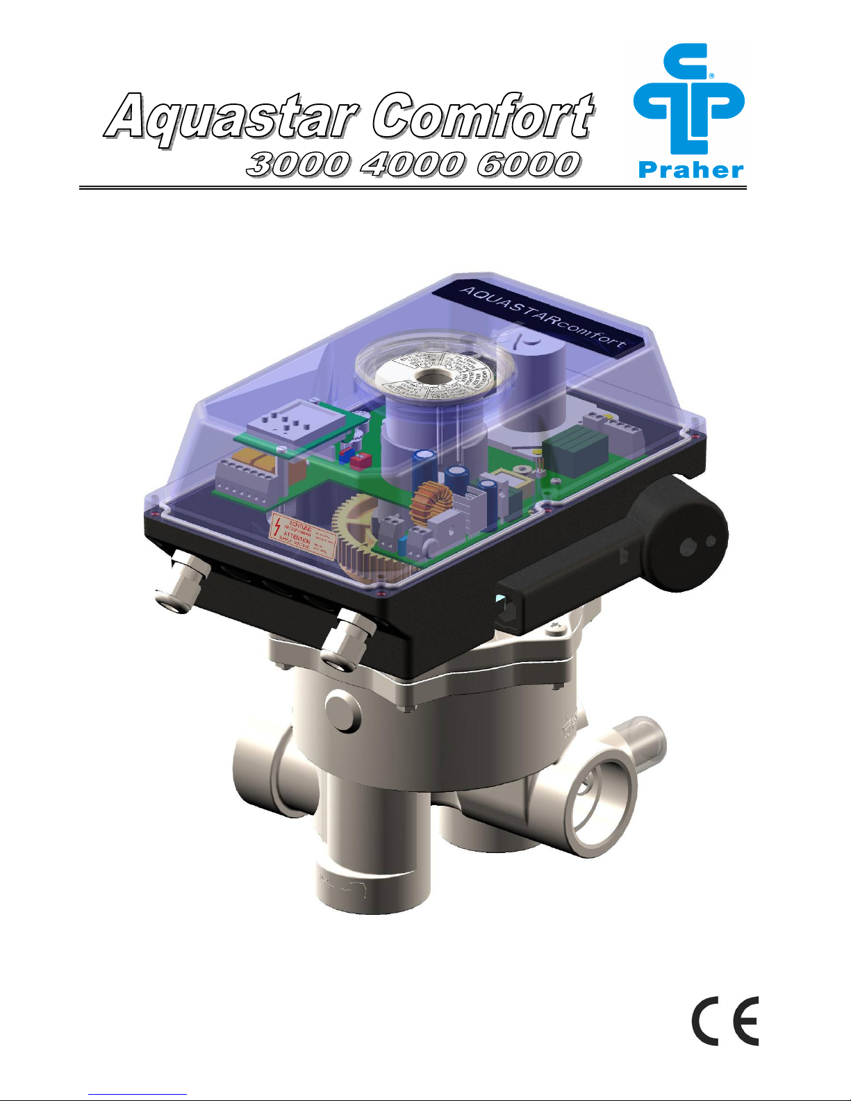
praher aquastar comfort 3000 User manual

Zertifiziert nach
certified acc. to
EN ISO 9001:2000

2
www.praher.com
TABLE OF CONTENTS
1. Copyrights......................................................................................... 4
2. Introductions operation manual...................................................... 4
3. Warranty and liability ....................................................................... 5
4. Instructions for safety during operation......................................... 5
5. Safety instructions ........................................................................... 5
6. Residual risk ..................................................................................... 6
6.1 Hazard generated by current ........................................................................6
6.2 Hazard generated by human error................................................................6
6.3 Hazard generated by current during cleaning work ...................................6
7. General .............................................................................................. 6
8. Designated use ................................................................................. 7
9. Assembly........................................................................................... 7
9.1 Function and installation chart.....................................................................7
10. Cycle sequence .............................................................................. 8
11. Flushing times and changeover.................................................... 8
12. Function of membrance keyboard ................................................ 9
12.1 Circulation ....................................................................................................9
13. Setting of times............................................................................. 10
13.1 Setting of delay time ..................................................................................10
13.2 Setting of backwash time ..........................................................................10
13.3 Setting of rinsing time ...............................................................................10
14. Setting of the electric pressure switch....................................... 10

www.praher.com 3
E
15.Programming the digital clock for the Aquastar Comfort.......... 11
15.1 Clock description.......................................................................................11
15.2 Operation Mode..........................................................................................12
15.3 First operation – setting the display language .......................................12
15.4 Creating a new program ...........................................................................12
15.5 Viewing and adapting a program.............................................................14
15.6 Deleting all programs ................................................................................14
15.7 Deleting single programs ..........................................................................14
15.8 Setting of date and clock...........................................................................15
15.9 Changeover Summer/Winter Time ...........................................................16
16. Electric Connection...................................................................... 17
17. Connecting diagram for pump .................................................... 18
18. Control Board ............................................................................... 19
19. Dimensions ................................................................................... 20
20. Exploded view drawing Aquastar Comfort................................. 21
21. Manual Override ........................................................................... 22
20.1 Dismantling.................................................................................................22
21.1 Installation ..................................................................................................23
22. Special Models Aquastar Comfort .............................................. 24
22.1 Aquastar Comfort 3500..............................................................................24
22.2 Aquastar Comfort 4500..............................................................................24
22.3 Aquastar Comfort 6500..............................................................................24

4
www.praher.com
1. Copyrights
This operation manual contains copyright protected information. All rights reserved to Praher
Kunststofftechnik GmbH.
This operation manual is designed for use by operating personnel only. Copying, reproduction
or translation of the present document into other languages in whole or in part is subject to
express written permission by Praher Kunststofftechnik GmbH.
© 2007 PRAHER Kunststofftechnik GmbH
Knowledge of the instructions contained in this operation manual is indispensable for preventing
failure and ensuring faultless operation of the Aquastar. Therefore, it is essential, that the
person in charge of operating the equipment is familiar with the present documentation.
2. Introduction to operation manual
This operation manual is intended to facilitate familiarization with the Aquastar and utilization of
the same for the intended purpose.
This operation manual contains important information for safe, proper and economical operation
of the Aquastar. Compliance with these instructions will contribute to
•preventing danger
•reducing repair costs and equipment failure, and
•increasing the liability and service life of the Aquastar
This operation manual supplements the instructions provided by existing accident prevention
and environmental protection regulations. It must be available at the place of utilization of the
equipment at any time and must be read by each person intending to use the Aquastar. This
means
•operation, including
•correction measures in case of faulty operation and
•maintenance
In addition to the operation manual and the compulsory accident prevention regulations
applicable at the place of utilization of the equipment, the generally subject specific technical
rules must be taken into account.
Service- Center (Tel.):
Austria ++43 / (0) 7262 / 61 178-0 austria@praher.com
Czech Republic ++42 / 0 / 204 / 637 637 czech@praher.com

www.praher.com 5
E
3. Warranty and liability
Warranty and liability claims in the context of damage to person or property shall be excluded
where such damage results from one or several of the causes listed below:
•Improper use of the Aquastar
•Improper installation, putting into operation, operation and maintenance of the Aquastar
•Operation of the Aquastar with defective or improper safety devices
•Non-compliance with the instructions contained in the operation manual for installation,
putting into operation, operation and maintenance of the Aquastar
•Unauthorized modification of the Aquastar
•Insufficient monitoring of components subject to wear and tear
•Inadequately performed repair of the Aquastar
•Damage of the Aquastar resulting from foreign matter or Force Majeure
Enduring damage due to neglect of the operation manual or due to damaging sealed parts lead
to a lapse of the warranty. We do not take any liability for resulting damages thereof! Please
read the operation manual carefully before starting operation.
4. Instructions for safety at work
•Each person, involved in the user’s facility, in the installation, dismantling, putting into
operation, operation or maintenance of the Aquastar must have read and understood the
entire operation manual and, in particular, the chapter ‘Safety Instructions’.
•The instruction and warning signs calling attention to dangers must be taken into account!
Dangerous voltage!
This is for your own safety!
5. Safety instructions
•This equipment has been built and examined according to safety precaution for electronic
devices and has left the plant in a perfect safety-related condition
•To keep this status and to guarantee a safe operation, the user must observe the safety
instructions, which are included in these instructions
•This installation work may only be undertaken by an authorized and licensed installer or
electrical business
•The electrical installations must be carried out according to the respective local and regional
regulations (e.g. OEVE, VDE,...) and possible official regulations
•the electrical connection must have separating device built into the permanently installed
electrical installation, which enables the disconnection of all electrical contacts with a contact
space of min. 3 mm from the mains. Pay attention that the supply voltage is correctly
protected and an earth-leakage circuit breaker ≤30 mA is installed.
•Only use the equipment in dry rooms, in which no combustible gasses and vapors are
present.

6
www.praher.com
•Do not put the equipment into operation immediately if it has been taken from a cold to a
warm area. The thereby developing condensation water could destroy your equipment
•If the equipment has visible damages, does not work anymore or has been stored under
adverse conditions for longer periods, then it is to be expected that a safe operation is no
more possible. In this case the equipment is to be secured against unintentional start-up and
if necessary to be decommissioned.
•Live parts can be uncovered when opening the cover or removing parts. Before an
alignment, maintenance, a repair or change of parts or devices, the equipment must be
separated from all voltage supplies, if opening the equipment is necessary. If after that an
alignment, maintenance or a repair on the opened equipment under voltage is inevitable, it
may only be done by experienced, skilled staff, which has knowledge of the associated
dangers and/or the relevant regulations.
•Capacitors in the equipment can still be charged, even if the equipment is separated from all
voltage supplies.
•Assembly and/or disassembly of the valve only in a pressure-free status (i.e. empty piping
beforehand)
•Valve flow and/or direction of flow must be considered.
6. Residual Risk
6.1 Hazard generated by current
Manipulation of the Aquastar by operating staff is strictly prohibited and may only
be performed by duly authorized staff, qualified for electrical work. Compliance
with the corresponding instruction and prohibition signs is required.
6.2 Hazard generated by human error
The operating staff must be instructed in regard to the residual danger resulting
from electricity and familiarized with correct operation. Efficiency of the safety
training must be verified.
6.3 Hazard generated by current during cleaning work
Cleaning of the Aquastar may only be performed after disconnection from power
supply (lever switch).
7. General
PRAHER Aquastar controls are significant technical products, which are manufactured with high
accuracy to the most modern technical production methods. Entitled complaints will naturally be
rectified as fast as possible if they occur. The equipment has a warranty after valid European
law. The warranty begins with the purchase date.
Each person involved in the operation and maintenance of the equipment must have
read and understood the present operation manual!
This is for your own safety!
Attention
!
For relief of the sealing system the valve is shipped on intermediate position
and is not sealed! Prior to operation it has to be electrically set to position “Filter“!

www.praher.com 7
E
8. Directions for use
This is a control unit for a multiport valve with 6 positions for fully automatic filter backwashing
according to need, i.e. pressure and/or time. A filter pump connection is activated about 20 sec
after the respective position is reached. The dry running design guarantees safe operation.
Additional electrical connections are available:
Backwash position; backwash and rinse position; for series connection of several valves
installed in series; for interruption of a heater or a heat exchanger before cycle start; for a ball
valve during the cycle.
9. Montage
Device installation – installation of the valve:
Install the valve in the conduit according to the labeling and the sketch below. Use adapter
unions. Threaded connections should be sealed only with Teflon strip. Although the device
works in any position, it should not be mounted actuator down, if possible. If the difference in
level between system and tank exceeds 3 meters, stop valves or non-return valves should be
installed to prevent severe damage to the actuator and the valve due to excessive pressure and
flow.
As filter medium can be washed out during backwashing and rinsing, we recommend fitting the
drain with a throttle. Otherwise a stuck valve disk can adversely affect the flawless functioning of
the Aquastar. Polluted or grainy filtering media require the use of adequate pre filters.
Important! During a cycle the filter pump motor must be shut off!
9.1 Function- and Installation Diagram
6-way valve type: 11/2“, 2“ and 3“
Connections: Thread or solvent socket (all connections open)
Max. operation pressure: ABS 11/2“, 2“, 3“ →3,5 bar
GFK 11/2“, 2“ →6 bar / GFK 3“ →5 bar
Filtering the medium (i.e. water)
Pool
→Pump →Valve (towards
filter) →Filter →Valve (away
from Filter) →Pool
Cleaning filter medium
(i.e. sand) after backwash cycle
Pool →Pump
→Valve (towards filter) →Filter
→
Valve (away from filter) →sewer
Cleaning filter medium
(i.e. sand) in counter flow
(reversed flow direction in filter)
Pool →Pump
→Valve (away from filter) →Filter
→Valve (towards filter) →sewer
Draining of the pool
with the pump
Pool →Pump
→Valve →Sewer
Circulating the medium
without Filter (Filter is bypassed)
Pool →Pump
→Valve →Pool
Pump →away from pump
Top →towards filter
Bottom →away from filter
Return →towards pool
Waste
→
towards
sewer

8
www.praher.com
10. Sequence of cycle
Starting position FILTER – device ON
−Start of backwash cycle by pressing the test key on the keyboard
−Control lamp ‘test key’ for backwash cycle activated is illuminated
−Output ‘heating’ clamp’ [22]-[21] switches off
−Set time of potentiometer (time delay) elapses (cooling down time for heat exchanger)
−Output ‘pump’ clamp [13]-[14] switches off (no continuity)
−Output ‘serial connection’ switches to clamp [18]-[19]
−Output ball valve switches from clamp [G]-[3] to [G]-[4]
Valve goes to backwash position
−Pump time delay of approx. 20 sec. elapses
−Output ‘pump’ clamp [13]-[14] closes
−Output ‘backwash’ switches to clamp [27]-[28]
−Set time of potentiometer elapses (rinsing period)
−Output ‘pump’ clamp [13]-[14] switches off
Valve goes to rinsing position
−Output ‘rinsing’ switches to clamp [24]-[25]
−Pump time delay of approx. 20 sec. elapses
−Output ‘pump’ clamp [13]-[14] closes
−Set time of potentiometer elapses (rinsing period)
−Output ‘pump’ clamp [13]-[14] switches off
Valve goes to filter position
−Output ‘ball valve’ switches from clamp [G]-[4] to [G]-[3]
−Pump time delay of approx. 20 sec. elapses
−Output ‘pump’ clamp [13]-[14] closes
−Output ‘heating’ switches to clamp [21]-[22]
−Output ‚serial connection’ switches to clamp [19]-[20]
11. Flushing and changeover times
Time delay 20 sec. - 23 min.
Changeover
Filter - Backwash ca. 45 sec.
Backwash 50 sec. - 9 min.
Changeover
Backwash time – Rinsing
ca.35 sec
Rinsing 25 sec. – 200 sec.
Changeover
Rinsing – Filter ca.25 sec
Cycle time 3 min – 40 min.
2
2
1
1
2
3

www.praher.com 9
E
12. Function of membrane keyboard
OFF
Pressing this key switches off the equipment, regardless of the valve position
ON
Pressing this key (yellow control lamp is illuminated) switches on the equipment, valves goes to
basic position - FILTER
TEST BUTTON
Pressing this key (green control lamp is illuminated) triggers the backwash cycle for the length
of a backwash procedure
WASTE
Pressing this key (red control lamp is illuminated) sets the valve to position “Waste“ Water is
being drained into the sewer system
Only with Comfort 3500, 4500 and 6500 by additional filter pump control
HAND
Pressing the HAND key makes the filter pump change from automatic to manual operation.
Filter pump switches on (independent from clock program)
AUTOMATIC
Pressing this key makes the filter pump change to automatic operation and only at the set filter
times the filter pump switches on (independent from clock program)
12.1 CIRCULATE
In order to set the automatic 6- way backwash valve to position “CIRCULATE“ and afterwards
again to position “FILTER’, following steps have to be made:
Go to basic position
Press keys “TESTBUTTON“ and “Waste“ at the same time,
(min. 4sec.) until the LED of the “TESTBUTTON“ is illuminated.
ATTENTION! After simultaneous pressing of the keys first the
LED of “TESTBUTTON” is illuminated and then the ‘WASTE’ LED,
briefly. Only then the LED of the “TESTBUTTON” starts blinking
and the Aquastar goes to position ‚circulate’
After “CIRCULATE“ is finished, press OFF
•Go to basic position
5
6
1
2
3
4
This product corresponds to the
following EEC-Guidelines
- Electromagnetic compatibility
89/336/EWG
- Low voltage directive
73/23/EWG
5
6
4
1
3
2
Comfort –
3500,4500,6500
2
2

10
www.praher.com
13. Setting of the times
13.1 Setting the time delay
- Set the time with the potentiometer. (knob ) (scale)
- Turn the potentiometer clockwise →longer time,
counter clockwise →shorter time
- Trigger backwash procedure with the TESTBUTTON
13.2 Setting the backwash time
- Set the time with the potentiometer. (knob ) (scale)
- Turn the potentiometer clockwise →longer time,
counter clockwise →shorter time
- Trigger backwash procedure with the TESTBUTTON
13.3 Setting the rinsing time
- Set the time with the potentiometer. (knob ) (scale)
- Turn the potentiometer clockwise →longer time,
counter clockwise →shorter time
- Trigger backwash procedure with the TESTBUTTON
14. Setting of the electric pressure switch
The operating pressure in the valve is measured by an electronic pressure switch. The
triggering by pressure is set with the switch S3, S4 at the control board. In order to change the
triggering pressure, turn the arrow (by using a screwdriver) clockwise or anti-clockwise until the
arrow points to the requested figure (see chart).
•Changeover 01 from 0,4 – 1,9 bar
•Changeover 02 from 2 – 5,75 bar
pressure (bar)
Raster Changeover 01 Changeover 02
0 0,4 2,0
1 0,5 2,25
2 0,6 2,5
3 0,7 2,75
4 0,8 3,0
5 0,9 3,25
6 1,0 3,5
7 1,1 3,75
8 1,2 4
9 1,3 4,25
A 1,4 4,5
B 1,5 4,75
C 1,6 5
D 1,7 5,25
E 1,8 5,5
F 1,9 5,75
1
2
3
S4
The pressure values are tested and set but can slightly vary
d
ue to
manometer tolerances
!
3
2
3
3
Pressure Switch

www.praher.com 11
E
15.Programming the digital clock for the Aquastar Comfort
15.1 Clock description
Display
A Function display of both left keys
B Channel displays
= Channel 1 EIN
= Channel 1 AUS
Channel 1 = C1, Channel 2 = C2
C Display for time, menu, prompt,…
D Display of day of the week
E Overview day- and switching program
F Display summer/winter time
G Power supply (permanent dots)
Battery supply (blinking dots)
H Function display of both right keys
General
The line in the middle shows the
menu item that can be chosen. If
this is confirmed with OK this
item is being activated.
Blinking texts or symbol
s need an
input.
If no input is being made within 2
minutes the clock sets back to
Auto- Mode
Keys
I Reset
With reset the programs stay as they are.
Date and clock have to be set again. Press Reset key with a
blunt object (i.e. ball point)
J Right key
K Left key with manual switch function
Fu
nction display of both right keys:
MENU Exit auto mode and enter programming mode
ESC press short = one step back
press long (~ 2 sec) = back to auto mode
OK Make choice and confirm
EDT Change request in Read-mode
N Do not execute command
J Execute command
DEL Delete
Function display of both left keys
:
Scroll upwards in the menu
Scroll downwards in the menu
Delete chosen item
Confirm chosen item
Press short = +1
Press long (~ 2 sec) = +5
Press short = -1
Press long (~ 2 sec) = -5

12
www.praher.com
15.2 Operation Mode
15.3 First operation – Choose menu language
15.4 Create a new program
Info
Left key = Channel 1
Right key = Channel 2 (only with 2-channel version)
Press 1x = FI ON
Press 2x = FI OFF
Press 3x = back to Auto mode
Info:
The clock is shipped in auto mode with pre-set time,
date and menu language English.

www.praher.com 13
E
Info:
The clock has 50 store spaces.
Example:
ON command for cannel 1 at
15.00 hrs. OFF command at
18.00 hrs.
-Choose program NEW
and confirm with OK
-The available storage
spaces are displayed
-Choose channel and
confirm with OK
-Choose daily block or
single day (free block
building) and confirm with
OK
-Input hour for ON
command (+/-) and confirm
with OK
-Input minute for ON
command (+/-) and confirm
with OK
-Input hour for OFF
command (+/-) and confirm
with OK
-Input minute for OFF
command (+/-) and confirm
with OK
- Program is stored
- Program goes to
READ, NEW, DEL.
More programs can
now be created.

14
www.praher.com
15.5 Viewing and adapting a program
15.6 Delete all programs
15.7 Delete single programs
Info:
-With
▲ ▼
scroll up and down
-By pressing EDT the program
can be edited. The steps are
the same as for creating a new
program.
Info:
-It is possible to delete all
programs by pressing Y
- By pressing N single programs
can be deleted
Info:
When deleting single programs all
subsequent program steps are
deleted (i.e. PO1 ON and PO2
OFF).

www.praher.com 15
E
15.8 Setting of date and time
Info:
Date and time are pre-set by factory.
Se
tting of AM/PM (12 ho rs/24 ho rs display

16
www.praher.com
15.9 Changeover Summer/Winter Time
Info:
Following settings are possible:
AUTO:
Pre-set setting by factory. This
is automatically recalculated for
every new year.
NO
No changeover
KAL
Program. Therefore the start
date of both summer and winter
time has to be input. The pre-
set factory settings are deleted.
The programmed summer and
winter time are automatically
recalculated for every new year.
The changeover is done at the
same set weekday in the same
week of the month.
Example:
21.03. Start Summer Time
31.10. Start Winter Time
Attention:
During changeover procedure
no changes at the clock must be
done!

www.praher.com 17
E
16. Electric Connection
a) Connection to the supply voltage
MVO 12-230VAC, 12-34VDC, 50/60 Hz
b) Trigger backwash procedure external
Activation of clamp [11/12] with potential free contact
Attention! Do not connect to voltage!
c) Connection for pump:
Potential free: I max. 8 A
On position FILTER, RINSE, CIRCULATE and WASTE and after approx.
20 sec. the clamps [13 →14] are interconnected.
d) Connection for ball valve
Potential free: I max. 8 A
On position FILTER the clamps [G→3] are interconnected.
On position WASTE and during the whole backwash cycle the clamps
[G→4] are interconnected.
e) Connection for 2
nd
rinse pump
Potential free: I max. 4 A
On position RINSE the clamps [27→28] are interconnected.
Only switches on if pump [13, 14] switches on.
f) Connection for signal on position RINSE
Potential free: I max. 4 A
On position RINSE the clamps [24→25] are interconnected.
g) Connection for signal on position CIRCULATE
Potential free: I max. 4 A
On position CIRCULATE the clamps [29→30] are interconnected
h) Connection for signal on position WASTE
Potential free: I max. 4 A
On position WASTE the clamps [31→32] are interconnected.
i) Connection for signal for heating / heat exchanger:
Potential free: I max. 4 A
After triggering the backwash cycle the clamps [21→22] are opened.
Filter pump stays on for the duration of the set time delay (knob )
Heat exchanger cools down and then pump switches off.
j) Connection for signal for serial connection:
Potential free: I max. 4 A
During the whole cycle [18→19] is interconnected.
Connection of more valves.
Technical data.
Voltage: MVO 12-230VAC, 12-34VDC
Protection rate: IP 65
Frequency: 50/60 HZ
Max. own consumption: ~ 4 Watt / 12 Watt 11/2“, 2“, ~ 4Watt / 20 Watt 3“
L1 N
11 12
13 14
4G
3
NO COM NCNO COM NC
27 28
24 25
29 30
31 32
21 22
1
18 19

18
www.praher.com
17. Connecting diagram for pump
Relais
Ballvalve
Kugelhahn
Relais Pumpe
Pump
Anschlußplan
Connecting diagram
Fuse
Sicherung
Versorgungsspannung
Electricity supply
12 - 230VAC
12 - 34VDC
230V
Pumpe
Pump
max. 8 A
4 G 3 13 14 11 12
rt bl L1 N
M
11
4 3
Kugelhahn Fa. Praher
Pos.1 Pos.2
(2*)
(6*) (3*)
Ballvalve
max. 4 A
Nachspülauslösung
Extern
Relais
Ballvalve
Kugelhahn Fuse
Sicherung
Versorgungsspannung
Electricity supply
12 - 230VAC
12 - 34VDC
4 G 3 13 14 11 12
rt bl L1 N
Motor-
schutz
Pumpe 400V
L1 L2 L3
T1 T3
Anschlußplan
Connecting diagram
11
4 3
Kugelhahn Fa. Praher
Pos.1
Pos.2
(2*)
(6*) (3*)
( *...alte Klemmenbezeichnung)
Ballvalve
max. 4 A
Nachspülauslösung Extern
Relais Pumpe
Pump

www.praher.com 19
E
18. Control Board

20
www.praher.com
19. Dimensions
Side Mount Top Mount
1 ½“ SM
1 ½“ TM
2“ SM
3“ SM
mm mm mm mm
A
99,5 X 110 170
B
90 X 114 165
C
29,5 31,5 38 50
D
48 47 60 85,5
R
61,5 59,5 81 110
F
163,5 160 210 306
G
295 291 339 436
H
39 41,5 36 50
I 87,5 90 114 165
J 117 117 117 117
K
175 180 228 117
L 125 125 125 330
M
165 165 165 125
N
140 140 140 165
O
18,5 18,5 26 35
P
X 62,5 X X
This manual suits for next models
5
Table of contents
Other praher Lighting Equipment manuals