WARRANTY CARD
Enduro Chlor Salt Water Chlorinator
Poolrite Equipment Pty. Ltd.
Your Poolrite Enduro Chlor is manufactured to the highest possible standards and most
up-to-date technology.
Accordingly the equipment carries the following Warranty, should a fault occur due to
faulty manufacture or materials.
Important
In the event of a fault covered by Warranty occurring, the Purchaser must, in the first
instance, contact Poolrite Equipment Pty. Ltd. or the closest authorised Poolrite
Distributor. Poolrite Warrant the original purchaser of the Power Pack and Chlorinator
Cell for a period of 1 year (12 months) from the Date of Purchase by the original
Owner, should examination disclose to its satisfaction that the Cell or Power Pack has
failed due to faulty manufacture or materials. In addition, for a further period of
2 years (24 months) the Chlorinator Cell will be repaired or replaced at Pro Rata cost
from Date of purchase by the original Owner.
The Warranty is void if the following occur:
1. Damage resulting from matters beyond Poolrite’s control.
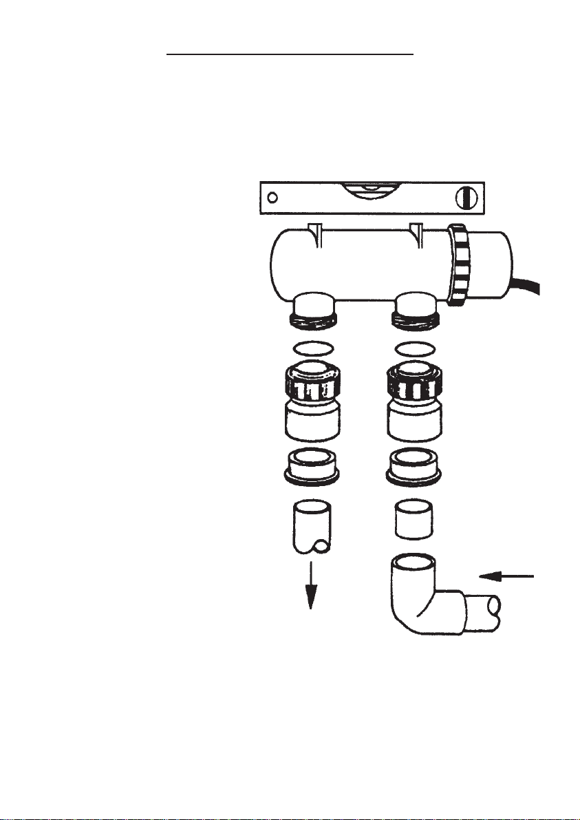
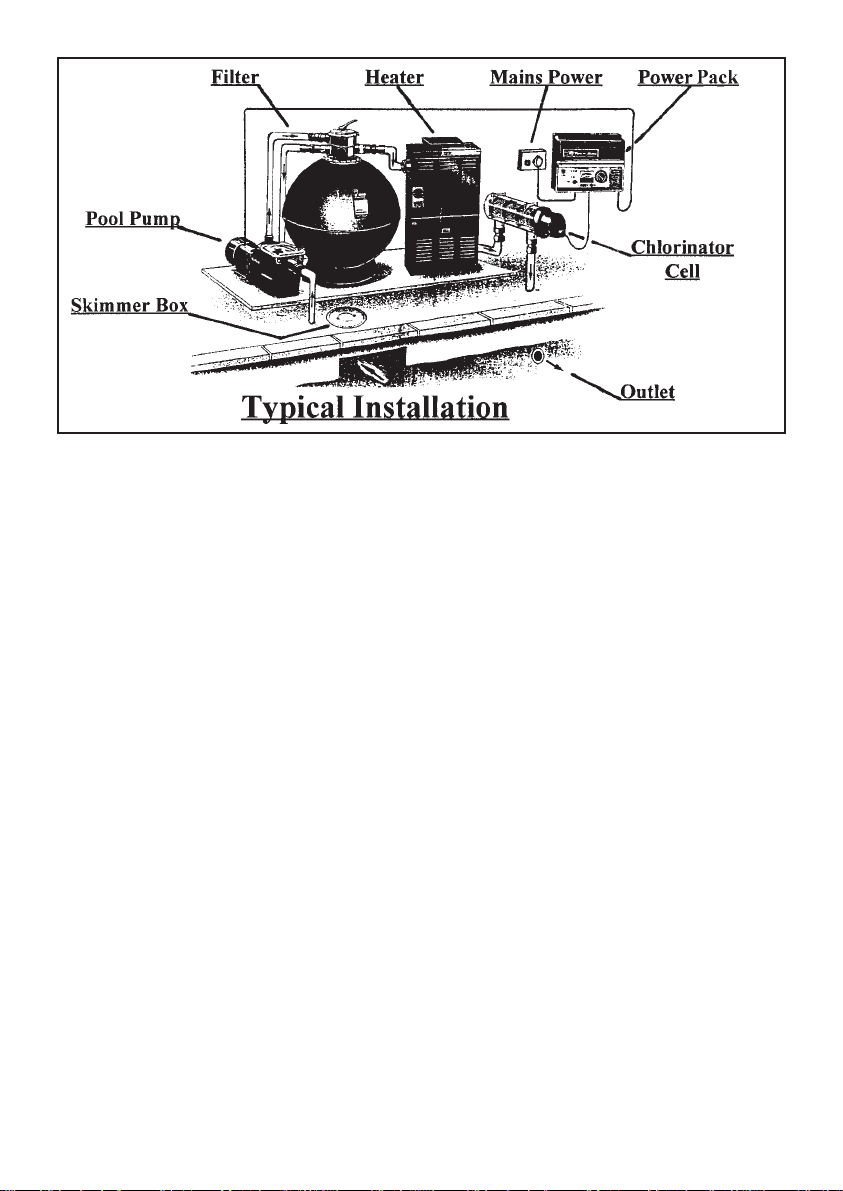
2. The Cell or Power Pack has been installed incorrectly and not in accordance with
these instructions.
3. The Power Pack has been connected to a power supply other than 240 volt 50 Hz.
4. The Cell or Power Pack has been used for any purpose other than swimming pool
or spa sterilisation.
5. Water above the temperature of 45°C has been permitted to flow through the Cell.
6. Water has not been permitted to flow freely through the Cell when turned on.
7. The safety flow detector or connections have been tampered with.
8. The Power Pack has been serviced by a person other than a person authorised to
do so by Poolrite or it’s agent.
9. The Cell power terminals have been submersed in acid solution when cleaning.
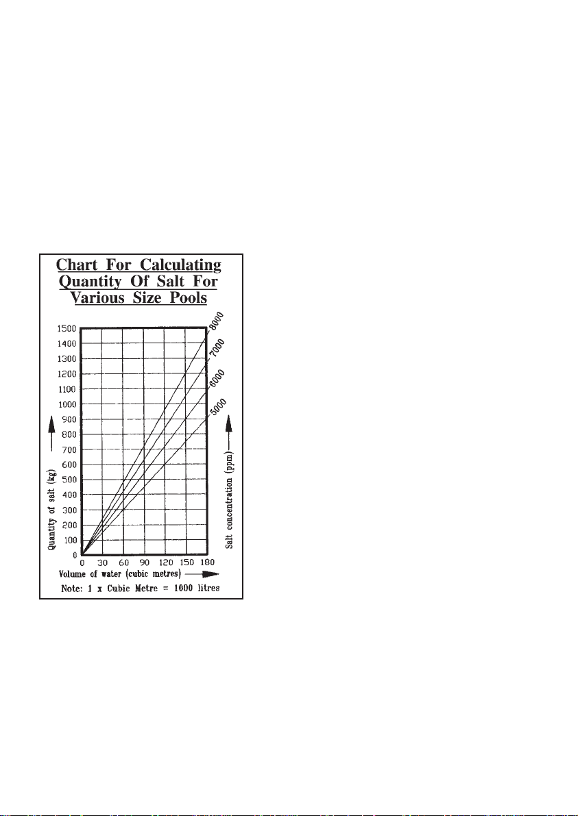
10. Non-swimming pool grade salt has been used in the pool.
This Warranty is applicable to workmanship and materials. Poolrite will repair or replace
at no charge, all parts returned freight paid, which display faulty workmanship or
materials.
Poolrite Equipment Pty. Ltd. accepts no responsibility for loss, damage or injury to
person or property arising from Warranty failure of equipment, or installation of that
equipment. Unless with the express prior authority of Poolrite, any repair or replace-
ment shall be provided only by Poolrite or it’s authorised distributors and this Warranty
shall not extend to any expenditure otherwise incurred.
Warranty Card
Name of Purchaser
Address
Purchased From
Date
Equipment and Model
IMPORTANT: This card must be filled in and
returned to Poolrite Equipment Pty. Limited
within 14 days of purchase to render the
Warranty effective.
Queensland Head Office
Sales & Export Brisbane
415 Creek Road,
P.O. Box 520,
Mt. Gravatt. QLD 4122
Telephone: (07) 3323 6555
Facsimile: (07) 3323 6500
Poolrite Equipment Pty. Ltd.
Unit 22, 761 Great South Road,
Penrose. Auckland
New Zealand.
Telephone: (09) 571 0210
Facsimile: 0800 766 574
Low Salt
Indicator
Chlorine
Control
Output Salt
Monitor
Model: SC25-TS
Pump
Outlet
Socket
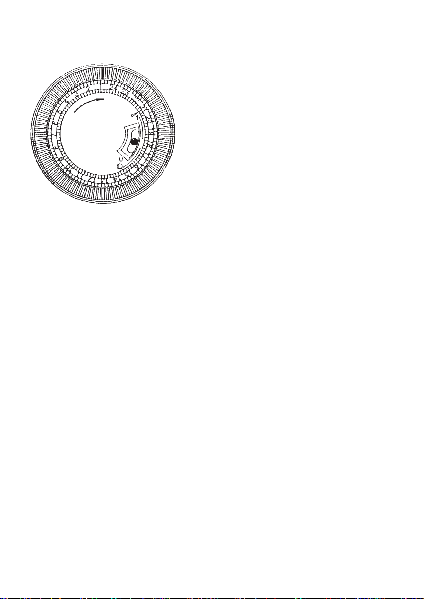
Time
Switch
Cable Entry Cover
PLR183_Endchlor MAN-cov 17/7/06 12:19 PM Page 2