Porta-Dock 100A User manual

12/19/07
Page 1 of 7
U:\Judy\INSTRUCTIONS CURRENT\INSTR LIFTS\LIFT INST 1284-12113 CANTILEVER.doc
PORTA-DOCK, INC.
100A 1200 LB. 84” WIDE ALUMINUM CANTILEVER BOAT LIFT
102A 1200 LB. 113” WIDE ALUMINUM CANTILEVER BOAT LIFT
Thank you for purchasing our product!
Please read these instructions and follow them step by step. *
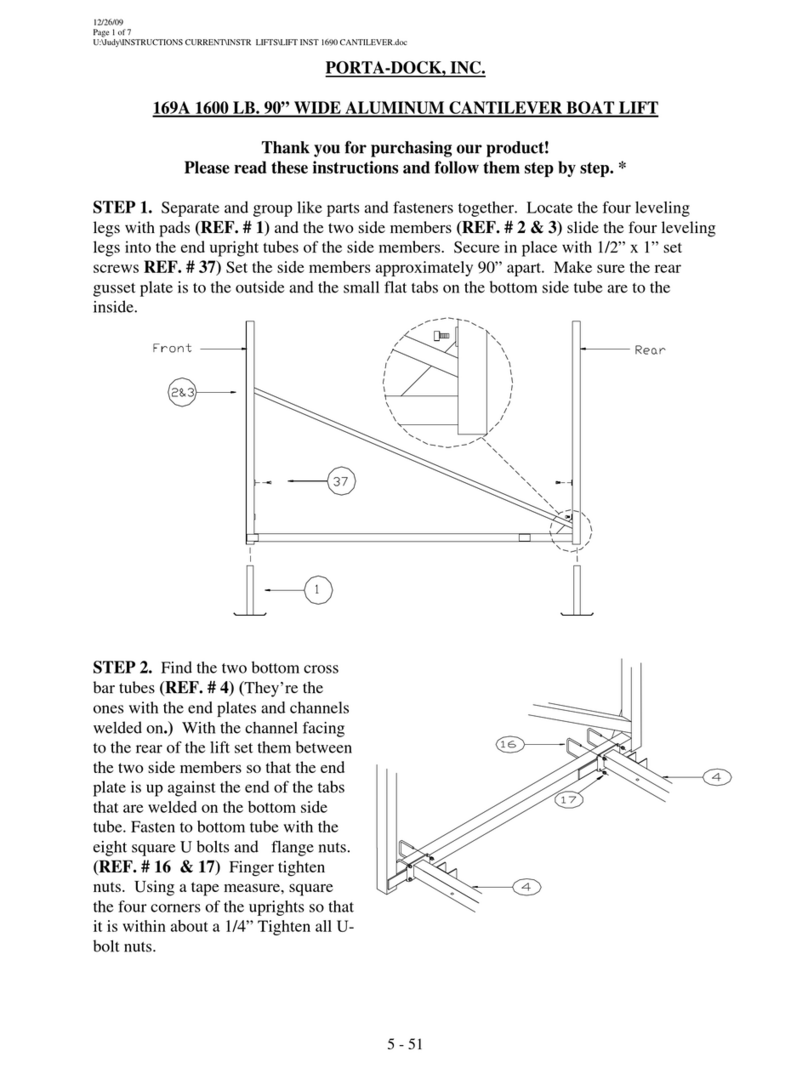
STEP 1. Separate and group like parts and fasteners together. Locate the four leveling legs with
pads (REF. # 1) and the two side members (REF. # 2 & 3) slide the four leveling legs into the
end upright tubes of the side members. Secure in place with 1/2” x 1” set screws REF. # 37) Set
the side members approximately 84” apart for 84” wide lifts and 113” apart for 113” wide lifts.
Make sure the rear gusset plate is to the outside and the small flat tabs on the bottom side tube
are to the inside.
STEP 2. Find the two bottom cross bar tubes
(REF. # 4) (They’re the ones with the end
plates and channels welded on.) With the
channel facing to the rear of the lift set them
between the two side members so that the end
plate is up against the end of the tabs that are
welded on the bottom side tube. Fasten to
bottom tube with the eight square U bolts and
flange nuts. (REF. # 16 & 17) Finger
tighten nuts. Using a tape measure, square
the four corners of the uprights so that it is
within about a 1/4” Tighten all U-bolt nuts.
5 - 43

12/19/07
Page 2 of 7
U:\Judy\INSTRUCTIONS CURRENT\INSTR LIFTS\LIFT INST 1284-12113 CANTILEVER.doc
STEP 3. Locate the two
H shape lifting arms
(REF. # 5). Slide a
Brass pivot bushing
(REF. # 18) into each
pivot cap on the ends of
the lifting arms. Place
the lifting arm into the
channels of the bottom
cross tubes and fasten
into place using and 1/2”
x 3” clevis pins and 1/2”
washers (REF. # 19 &
20). Secure with pins.
(REF. # 21).
STEP 4. Find the lifts top bed member (rec. frame 81” x 86 3/4” (REF. # 6). Set the bed
member pivot channels into the ends of the lifting arms. The pivot channels on the outside of the
bed are toward the front of the lift. Locate the two front pulley brackets, 1/2” x 6 1/2” clevis
pins and 1/2” washers (REF. # 13, 22 & 20). On the front corner of the bed, place a pulley
bracket with the pulley sheave toward the outside, in between the corner angle and the pivot
channel. From the corner angle side, slide a 1/2” x 6 1/2” clevis pin through the angle and the
pulley bracket into two 1/2” washers and through the lifting arm and pivot channel. Place
another 1/2” washer over the clevis pin and secure with cotter pin. (See illustration after STEP
5)
STEP 5. Fasten the rear lifting arms to the back pivot channels of the member with 1/2” x 3”
clevis pins, 1/2” washers and cotter pins (REF. # 19, 20 & 21).
5 - 44

12/19/07
Page 3 of 7
U:\Judy\INSTRUCTIONS CURRENT\INSTR LIFTS\LIFT INST 1284-12113 CANTILEVER.doc
STEP 6. Find the winch (REF. # 8) decide what side the winch is going on. The winch is
simply turned over to go either left or right. Bolt the winch to the inside of the front upright
using 3/8” fender washers (REF. # 25) on the tube side and standard 3/8” washers (REF. # 28)
on the winch side. Use 3/8”x 3” bolts. (REF. # 29) Find the lift cable (REF.NO. 14), thread
the plain end of the cable through the hole in the side of the winch drum.
STEP 7. Locate the two round U bolts (REF. # 23) and the one pulley and chain assembly
(REF. # 24). Place the U-bolt through the chain link and into the two holes directly below the
winch and above the diagonal tube of the side member. Secure the U bolt with 3/8” fender
washers and nylock nuts (REF. # 25 & 26). Only finger tighten nuts at this time. Place the
other U-bolt through the cable thimble (REF. # 27) and secure to opposite side member in the
same manner. Pass the cable through the pulley sheave in the pulley bracket. Then run the cable
up to and through the pulley on the front bed cross tube across to and through the other pulley.
Bring the cable back up to the other U bolt around the cable thimble and secure with cable
clamp. (REF. # 30). Install lift wheel (REF. # 9) on winch and secure with winch hardware.
Turning lift wheel clockwise raise the bed of the lift 3/4 of the way up.
5 - 45

12/19/07
Page 4 of 7
U:\Judy\INSTRUCTIONS CURRENT\INSTR LIFTS\LIFT INST 1284-12113 CANTILEVER.doc
STEP 8. Find the two front angle braces (REF. # 7) (description 1 1/4” X 1 1/4” X 36” angle
with slotted holes on each end)Bolt the one end to the inside face of the front upright tube with a
3/8” x 3” bolt, washer and nut. (REF. # 29, 28 & 31) Bolt the other end to the side of the
bottom cross tube using the same size bolt, washer and nuts. Tighten up bottom cross member
nut first so that the slot is about in the middle of the bolt. Check front upright for straightness.
Adjust upright if necessary and tighten bolt in upright tube
STEP 9. Take the two stop chains (REF. # 32) and bolt the one end to the bottom side of the
diagonal brace tube of the side member using a 3/8” x 3” bolt (REF. # 29) Place the chain link
between two 3/8” washers and secure with a 3/8” nylock nut (REF. # 28 & 26 ). Tighten
enough so that the nylock nut is fully engaged with the thread of the bolt, yet chain should still
turn freely. Fasten the other end of the chain to the inside of the bottom corner of the angle of
the top bed cross tube with a 3/8” x 1 1/2” bolt, washers and nylock nut. (REF. # 33, 28 & 26)
Again tighten the nylock nut so that the nylon of the nut is engaged with the threads of the bolt,
but the chain can still turn freely.
5 - 46

12/19/07
Page 5 of 7
U:\Judy\INSTRUCTIONS CURRENT\INSTR LIFTS\LIFT INST 1284-12113 CANTILEVER.doc
5-47

12/19/07
Page 6 of 7
U:\Judy\INSTRUCTIONS CURRENT\INSTR LIFTS\LIFT INST 1284-12113 CANTILEVER.doc
PARTS LIST
100A 1200 LB. 84” WIDE ALUMINUM CANTILEVER BOAT LIFT
102A 1200 LB. 113” WIDE ALUMINUM CANTILEVER BOAT LIFT
100A 102A
REF.NO. PART NO. DESCRIPTION 1284 12113
1 62H LEVELING LEG 4 4
2 10G SIDE MEMBER RIGHT 1 1
3 11G SIDE MEMBER LEFT 1 1
4 12G BOTTOM CROSS TUBE 1284 2 -
21G BOTTOM CROSS TUBE 20113 - 2
5 17G LIFTING ARMS 1284 2 -
19G LIFTING ARM 20113 - 2
6 32H TOP BED MEMBER 1284 1 -
07R TOP BED MEMBER 12113 - 1
7 41218 DIAGONAL FRONT BRACE 2 2
8 3180 WINCH DL B1200 1 1
9 23E WINCH WHEEL SMALL 1 1
13 99F PULLEY BRKT 3” X 2.375” 2 2
14 3054 CABLE 1/4” X 26’ 1 1
15 4504 SPINNER KNOB 1 1
16 5046 U-BOLT SQ 2” 8 8
17 5156 FLANGE NUT 3/8” 16 16
18 3313 BRASS BUSHING 5/8” X 2” 8 8
19 5097 CLEVIS PIN 1/2” X 3” 6 6
20 5071 WASHER 1/2” 12 12
21 5025 COTTER PIN 1/8” X 1 1/4” 8 8
22 5190 CLEVIS PIN 1/2” X 6” 2 2
23 5034 U-BOLT ROUND 2 2
24 E75 PULLEY 2 1/2” 2 LINK 1 1
25 5067 WASHER FENDER 3/8” 6 6
26 5038 NUT NYLOCK 3/8” 8 8
27 5044 CABLE THIMBLE 1/4” 1 1
28 5070 WASHER 3/8” 20 20
29 5084 BOLT 3/8” X 3” 8 8
30 5004 CABLE CLAMP 1/4” 1 1
31 5056 NUT 3/8” STANDARD 10 10
32 3093 CHAIN STOP 3/16” X 27 LINK 2 2
33 5155 BOLT 3/8” X 1 1/2” 2 2
37 5174 SET SCREW 1/2” X 1” 4 4
38 3821 CAP 2” SQUARE GRAY 3 3
39 3828 CAP .343 X 1/2” PVD 4 4
5 - 48

10/13/08
LIFT WARNING SHEET
IMPORTANT BOAT LIFT SAFEGUARDS
The boat lift system must be assembled, installed and operated correctly or mechanical failure
causing injury or death may occur. Be sure that all persons operating the lift are familiar with the
correct operating procedures and safety guidelines.
CAUTION - Keep all body parts inside the boat when entering or exiting the boat lift. Do not try to
manually guide the boat into position.
CAUTION – Keep clear of chains, cables, and all moving parts when operating the lift.
CAUTION – On lifts that have a chain drive winch, the cover must be in place while operating.
CAUTION – Never allow anyone to swim around or climb on the lift structure at any time.
CAUTION – Do not operate the lift with people inside the boat.
CAUTION – Never exceed the rated capacity of the lift as this may cause excessive damage to the lift.
Do not allow people to sit in a boat that is on the lift as this may cause to lifts capacity to be exceeded. An
uncovered boat can fill up with water and cause the capacity of the lift to be exceeded.
CAUTION – Before any adjustments are made to the lift, or any work is done, the boat must be removed
and the bed must be fully lowered.
CAUTION – Winches are pre set from the manufacturer and do not need adjusting.
CAUTION – If using a winch with a remote control, the operator must be close enough to the lift to be
sure that no one is around or on the lift, and to be sure that the lift is operating properly
CAUTION - After installation the lift must be leveled in order to operate properly. If the lift is not
leveled properly there will be excessive stress on isolated areas causing failure or damage to the lift.
Before installing the lift each year inspect the cables, pulleys, and all moving parts for wear. Immediately
replace any part that has excessive wear. Check the brake pad in the winch, if it is worn down to 1/16”
thick, cracked, or glazed over, replace it immediately. Check all the bolts to make sure they are tight. On
vertical lifts the cables may stretch and will need to be tightened so there is equal tension on all the cables.
5 - 49

Porta-Dock, Inc.
This manual suits for next models
1
Table of contents
Other Porta-Dock Lifting System manuals