Portech IS-380 User manual

IS-380
IP Alarm trigger
User Manual
PORTech Communications lnc.

Contents
1.Brief Introduction ................................................................................................. 1
2.Main body Size.................................................................................................... 1
3.Product Package Content.................................................................................... 1
4.Panel Introduction:............................................................................................... 2
5.IS Music/Audio Server and IS-380 diagram......................................................... 3
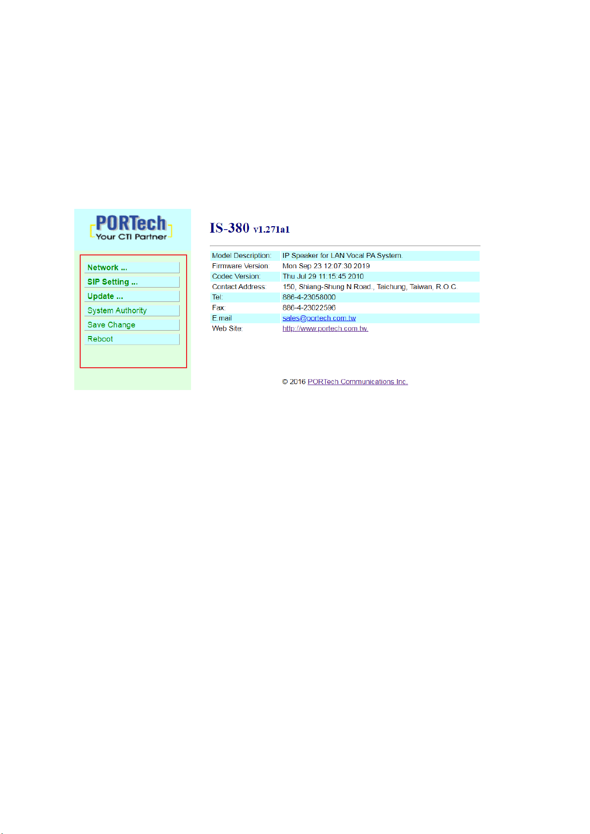
6.Web picture ............................................................................................... 4
7.Set the main interface.......................................................................................... 5
7.1 Description of function items...................................................................................... 5
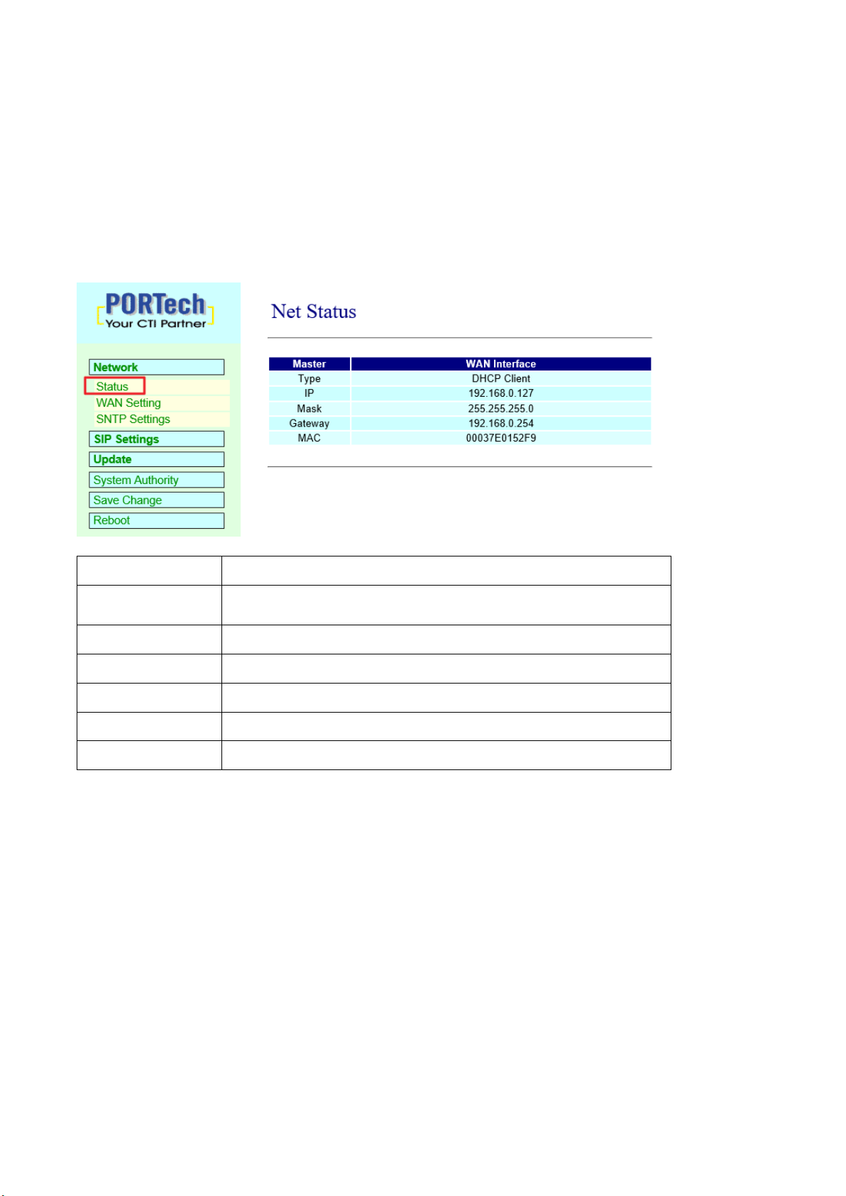
8.Network (Network Environment).......................................................................... 6
8.1 Status (network status)................................................................................................ 6
8.2 WAN Setting (WAN network setting) ....................................................................... 7
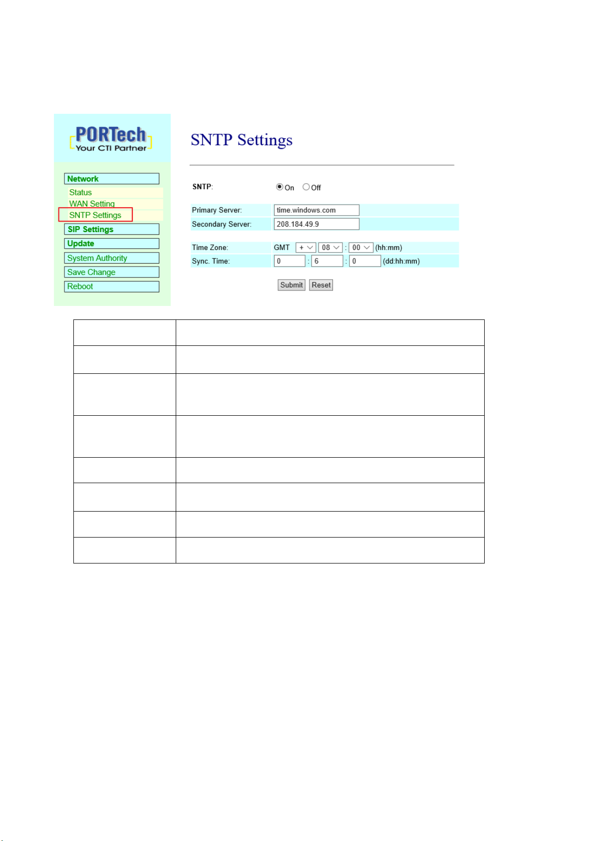
8.3 SNTP Setting ............................................................................................................... 8
9.SIP Setting .......................................................................................................... 9
9.1 Port Setting (SIP port setting).................................................................................. 9
9.2 Switch Setting.............................................................................................................. 10
10. Update............................................................................................................ 11
10.1 New Firmware ........................................................................................................ 11
11.System Authority ............................................................................................. 14
12. Save Change.................................................................................................. 15
13. Reboot............................................................................................................ 15

1
1. Brief Introduction
IS-380 is a IP Alarm trigger .
Using dry contact connect with sensor
when trigger NO->NC or NC->NO,audio music server will active schedule to play
mp3/wav file to single speaker or group speaker to Alarm
Example:
Reservoir gate have a sensor and connect with our IS-380 via dry contact
The reservoir gate open, trigger NO->NC. IBS System will play a mp3 preprogram file to
specific speaker
2. Main body Size
(L) 17 X (W) 14.5 X (H) 3.9 cm
3. Product Package Content
3.1 Host X 1
3.2 Ethernet line 2M X 1
3.3 Power Adaptor (output : DC 12V -- 1A) X 1

2
4. Panel Introduction:
(1) ALARM INPUT:dry contact input; can connect with device that have dry contact ouput
(2) DC 12V : power supply input interface
(3) LAN: network port; insert network line to establish network connection
(4) PWR: power supply indicator lamp
(5) STATUS :
indicator lamp of sound output state
Constantly on: Audio Out 2 has sound output
Flash at 3 seconds intervals: the broadcast point is successfully registered in IS
Music/Audio Server
Blink continually: trigger NO->NC or NC->NO
Off: the broadcast fails in registering in IS Music/Audio Server
(6) Link : network connection indicator lamp

3
5. IS Music/Audio Server and IS-380 diagram
sensor
dry contact

4
6. Web picture
Step 1: open IE browser (or other browser software), input [http://192.168.0.100]
Step 2: enter [Login WEB] picture, input [Username & Password (defaults: username:
voip,Password: 1234)] , and then click [OK] to enter the equipment
management interface after confirming the password is correct (as shown in
the following picture).
Step 3: you can see [System Information] interface after entering the system, which
provides data of Model Name, Firmware Version and Code Version.

5
7. Set the main interface
It provides the following function items: Network, SIP Setting, System Auth, (Account
and Password Change), SaveChange, Update and Reboot. Description of function
items.
7.1 Description of function items
(1) Network : Network provides Status and WAN Setting
(2) SIP Settings : SIP Setting provides Service Domain (SIP registration setting),
Port Setting (SIP and RTP ports setting),Code Setting (voice format setting),
Audio Setting (loudspeaker volume and sound detection setting),Other Setting.
(3) Update : Update (firmware updating) provides Firmware (firmware updating),
Default Settings (factory reset).
(4) System Authority : System Auth (Account and Password change) provides
change of user's account and password.
(5) Save Change : Save Change provides setting of save change environment.
(6) Reboot : Reboot provides the function of rebooting a device.

6
8. Network (Network Environment)
8.1 Status (network status)
Network Status (network status) picture shows the date of current network environment
status (as shown in the following picture)。
Column
Introduction
Master
Show the network environment data of the network port
(WAN port)
Type
Show current network connection mode
IP
Show set or gained network address data
Mask
Show set or gained network coding data
Gateway
Show set or gained preset gateway data
MAC
Show MAC position data of the machine

7
8.2 WAN Setting (WAN network setting)
WAN Setting (WAN network setting) picture provides WAN network connection mode.
WAN Setting
Provide WAN port network environment setting data
IP Type
Preset to be DHCP Client network mode. Provide Fixed IP, DHCP Client
(automatically obtain an IP address) and PPPoE mode.
Fixed IP: set IP address manually.
DHCP Client (automatically obtain an IP address): automatically obtain
an IP address.
PPPoE (connect PPPoE): adopt PPPoE connection mode.
IP
Show IP address data. Show gained or set IP address data.
Mask
Show subnet mask data. Show gained or set subnet mask address data.
Gateway
Show preset gateway data. Show Show gained or set preset gateway
address data.
DNS Server1
Preset to be 168.95.192.1; show gained or set first DNS server's
address data; IP or Domain Name can e input
DNS Server2
Preset to be 168.95.1.1; show gained or set second DNS server's
address data; IP or Domain Name can e input
MAC
Show MAC position data of the machine
PPPoE Setting
Provide PPPoE connection data
User Name
Set connection account name, in which figures or strings are available
Password
Set connection account password, in which figures or strings are
available
Submit [key]
Execute storage and change setting.
Reset [key]
Clear input data.
*Press [submit] to finish storage setting after changing the data to be adjusted, and select the main
menu's [SaveChange], to execute storage change setting, the system will restart automatically *

8
8.3 SNTP Setting
SNTP Setting picture provides server address and timing time.
Column
Introduction
SNTP
Preset to be On (start); timing function. Turn off timing
function when it is set to be Off.
Primary Server
Preset to be time.windows.com; the first syn-position
timing server address. Input IP or Domain Name
address.
Secondary
Server
Preset to be 208.184.49.9; the second syn-position
timing server address. Input IP or Domain Name
address.
Time Zone
Preset to be GMT + 08:00 (hh:mm); timie zone material.
Sync. Time
Preset to be 1:00:00 (1 day); timing time. Correct the
host time every a certain peroid.
Submit [key]
Execute storage and change setting.
Reset [key]
Clear input data.
Press [submit] to finish storage setting after changing the data to be adjusted, and
select the main menu's [SaveChange], to execute storage change setting, the system
will restart automatically *

9
9. SIP Setting
9.1 Port Setting (SIP port setting)
Port Setting (SIP port setting) picture provides setting of SIP communication port
positions.
Column
Introduction
SIP Port
Preset to be 5060; set SIP port position.
Submit [key]
Execute storage and change setting.
Reset [key]
Clear input data.
Press [submit] to finish storage setting after changing the data to be adjusted, and select the
main menu's [SaveChange], to execute storage change setting, the system will restart
automatically *

10
9.2 Switch Setting
Setting about connecting with IS Music/Audio Server and 及Trigger mode
Column
Introduction
Active
Default No;set if connect with IS Music/Audio Server or
not
SID
System provide device ID auto
Debounce
Default: 200ms ; set the Debounce time of
Trigger contactor.if default 200ms,
triggerduration is less than 200ms,it mean No trigger
LED Alert
Default Short ; set STATUS LED flash trigger mode
Name
Define display name in IS Music/Audio Server
Server
Set IS Music/Audio Server IP address and port
Status
Display current status if connect with IS Music/Audio
Server and dry contact status
Press [submit] to finish storage setting after changing the data to be adjusted, and
select the main menu's [SaveChange], to execute storage change setting, the system
will restart automatically *

11
10. Update
10.1 New Firmware
Code Type
Preset to be Risc (.gz). Select the type of documents to be
updated. Provide Risc (system firmware. gz) and DSP
(DSP
firmware. ds) updating modes.
File Location
Input file positon or name to be updated or press [Browse] to
select file data; version name of the file to be updated.
Submit[key]
Execute storage and change setting.
Reset [key]
Clear input data.
Step 1: click [Updte€New Firmware] on the surface to enter [Update Firmware], to set
version to be updated and select Code Type: Risc, then set File Location data, to
set [Broswe] key (as shown in the following picture).

12
Step 2: enter [select file] interface, to select [gz] file to be updated [for example,
VP5110_70105.gz], and then press [open] (as shown in the following picture), to
return to the main interface.
Step 3: back to [Update Firmware], wherein [File Location] has data to be updated if it is
confirmed to be correct; please press [Submit] to start updating (as shown in the
following picture).
Step 4: enter [information prompt] picture,showing [please do not pull out power supply
equipment at random in version updating, the updating time is about 3 minutes]
(as shown in the following picture).
Step 5: back to the main interface after firmware updating, please press [reload
(F5)].Conduct other settings.

13
10.2 Default Setting
Restore Default Setting provides data content of all change setting (not containing data
in Network) to restore default setting value; the system will automatically restart.
Column
Introductio
n
Restore [key]
Remove all change setting data to restore default
setting.
Step 1: click [Update€Default Setting] in the main interface to enter [Restore Default
Settings]. Please press [Restore] to restore default, to clear all settings and
restart the equipment automatically (as shown in the following ficture).
Step 2: enter the informatoin prompt interface to finish clear setting and restart the
system, please wait (as shown in the following picture).
Step 3: back to the main interface after starting up, please press [reload (F5)] Conduct
other settings

14
11. System Authority
Set system authority
Colum
n
Introductio
n
New username
Input the new user's data Input digits or string.
New password
Input new password Input digits or string.
Confirmed password
Input and confirm password Input digits or string.
Submit [key]
Execute storage and change setting.
Reset [key]
Clear input data.
Press [submit] to finish storage setting after changing the data to be adjusted, and
select the main menu's [SaveChange], to execute storage change setting, the
system will restart automatically *

15
12. Save Change
Save Changes provides save changes setting and restart system automatically.
Column
Introductio
n
Save [key]
Execute storage and change setting.
13. Reboot
Reboot System interface provides manual reboot.

16
Step 1: click [Reboot] in the main interface to enter [Reboot System] and then press
[Reboot] to reboot the system (as shown in the following picture).
Column
Introductio
n
Reboot [key]
Reboot the equipment
Step 2: enter the information prompt interface, showing that the system is rebooting,
please wait (as shown in the following picture); do not pull out power supply
equipment at random at the moment.
Step 3: back to the main interface after starting up, please press [reload (F5)] to conduct
other environment settings.

Table of contents