Porter 12002 Sportsonic II User manual

INSTALLATION &OPERATION MANUAL
R
EMOTE
C
ONTROL
S
YSTEM
F
OR
B
ASKETBALL
B
ACKSTOPS
,
G
YMNASIUM
D
IVIDERS
,E
TC
.
No. 12002 Sportsonic£II
INST 00358 042
¤2015 PORTER ATHLETIC, INC. ALL RIGHTS RESERVED. 11-6-2015
SAVE THESE INSTRUCTIONS FOR FUTURE REFERENCE,
AND TO ORDER REPLACEMENT PARTS

2

3
SPECIFICATIONS
PORTER No. 12002-200 SPORTSONIC
£
II SPORTS COMPLEX CONTROL SYSTEM
(FOR OPERATION OF No. 00706-000 or 00707-000 ELECTRIC WINCHES OR No.
665, 670, 675 or 2080 DIVIDER CURTAIN OPERATORS)
Winch shall be controlled by a radio control system (Sportsonic£II) to eliminate complicated control wiring, wall boxes and
individual key switches as on conventional remote control key switch systems. Sportsonic£II portable hand-held
transmitter (5-1/2" x 3-3/8" x 1") shall be specified. The No. 12002-100 transmitter will operate up to ninety-nine individual
winches. Numeric LED clearly displays selected channel. Power supply for transmitter shall be a standard 9-volt battery.
Transmitter shall operate on a digitally encoded carrier frequency of 315 MHz.
Each electric winch shall be equipped with a commercial type 115 VAC receiver with a coding switch for individual
operation by the portable transmitter. Receiver shall be factory wired and installed in a standard non-metallic enclosure
(6" x 4" x 2-3/8") with a 6’-0" long SJ cord with a NEMA L5-15 molded twist-lock grounded plug attached. Matching flange
type receptacle shall be mounted in a standard 4" square cover plate (box by others) for power supply. Enclosure shall be
furnished with a 4-pole twist-lock grounded type NEMA L14-20 receptacle to accept the power/control cable from the
electric winch.
Receiver shall allow for dual control of equipment (Sportsonic£II or key switch). Each radio-controlled receiver shall
include an external 3-screw terminal strip for optional low voltage, key switch type control. The terminal strip shall allow
for connection of low voltage, dry circuit type (5 volt maximum) key switch wires (up, down and common). Circuit board
programmed EEPROM shall provide logic for an interlocking feature to eliminate conflict between radio and key switch
control input. Key switch option shall be specified when a secondary or back-up method of winch operation is desired.
Radio control systems without optional low voltage, key switch type control shall not be considered equal.
All units to be factory tested for a 100' (nominal) operating range. Coding switch shall be configured in field for
independent operation.
Wiring of all electrical components shall be in accordance with local codes, and in accordance with manufacturer's
instructions.
All conduit, wiring, junction boxes and components not specified herein shall be furnished and installed by the electrical
contractor.
ISSUED NOVEMBER 6, 2015, SUBJECT TO CURRENT MANUFACTURING PROCEDURES AND CHANGES
COPYRIGHT 2015 – PORTER ATHLETIC EQUIPMENT COMPANY – ALL RIGHTS RESERVED
B-2002

4

5
SPECIFICATIONS
PORTER No. 12002-250 SPORTSONIC
£
II SPORTS COMPLEX CONTROL
SYSTEM (FOR OPERATION OF No. 00706-000 or 00707-000 ELECTRIC
WINCHES OR No. 665, 670, 675 or 2080 DIVIDER CURTAIN OPERATORS)
With DUAL CONTROL OPTION (SPORTSONIC
£
II or KEY SWITCH)
Winch shall be controlled by a radio control system (Sportsonic£II) to eliminate complicated control wiring, wall boxes and
individual key switches as on conventional key switch systems. Sportsonic£II portable hand-held transmitter (5-1/2" x 3-
3/8" x 1") shall be specified. The No. 12002-100 transmitter will operate up to ninety-nine individual winches. Numeric
LED clearly displays selected channel. Power supply for transmitter shall be a standard 9-volt battery. Transmitter shall
operate on a digitally encoded carrier frequency of 315 MHz.
Each electric winch shall be equipped with a commercial type 115 VAC receiver with a coding switch for individual
operation by the portable transmitter. Receiver shall be factory wired and installed in a standard non-metallic enclosure
(6" x 4" x 2-3/8") with a 6'-0" long SJT cord with a NEMA L5-15 molded twist-lock grounded plug attached. Matching
flange type receptacle shall be mounted in a standard 4" square cover plate (box by others) for power supply. Enclosure
shall be furnished with a 4-pole twist-lock grounded type NEMA L14-20 receptacle to accept the power/control cable from
the electric winch.
Receiver shall allow for dual control of equipment (Sportsonic£II or key switch). Each radio-controlled receiver shall
include an external 3-screw terminal strip for optional low voltage, key switch type control. The terminal strip shall allow
for connection of low voltage, dry circuit type (5 volt maximum) key switch wires (up, down and common). Circuit board
programmed EEPROM shall provide logic for an interlocking feature to eliminate conflict between radio and key switch
control input. Key switch option shall be specified when a secondary or back-up method of winch operation is desired.
Radio control systems without optional low voltage, key switch type control shall not be considered equal.
All units to be factory tested for a 100' (nominal) operating range. Coding switch shall be configured in field for
independent operation.
Wiring of all electrical components shall be in accordance with local codes, and in accordance with manufacturer's
instructions.
All conduit, wiring, junction boxes and components not specified herein shall be furnished and installed by the electrical
contractor.
ISSUED NOVEMBER 6, 2015, SUBJECT TO CURRENT MANUFACTURING PROCEDURES AND CHANGES
COPYRIGHT 2015 – PORTER ATHLETIC EQUIPMENT COMPANY – ALL RIGHTS RESERVED
B-2002-5

6
SPORTSONIC
£
II
INSTALLATION AND OPERATING INSTRUCTIONS
PARTS LIST
12002-200 12002-250
Item No. Part No. Quantity Quantity Description
1 XELC 12002 200 1 1 Sportsonic£II Receiver
2 ELEC 00064 000 1 1 3-Prong Twist-Lock Receptacle
3 ELEC 00126 0G0 1 1 1/2" deep Cover Plate
4 ELEC 00221 002 1 1 Cable Tie 14" Lg. - Black
5 12002-100 Sportsonic£Transmitter – 99 Positions
6 ELEC 00086 000 1 Key Switch Assembly
Quantity of Sportsonic£II Transmitters to be specified
One Sportsonic£II Receiver required per device to be controlled.
1. Establish backstop or divider curtain operating code numbers (1 thru 99). Use numbers on floor plan drawing if available – Main
court #1 and 2, Cross Courts #3, 4, 5, 6, etc. Suggest marking backstops with operating numbers to avoid confusion.
2. At the cord connector end of Sportsonic£II receiver enclosure, rotate small cover up, to expose DIP switch window. Locate
receiver DIP switch module inside enclosure window (small black plastic module with white slide tabs numbered 1 thru 7). Set
the receiving code module on each receiver per the following chart. As each box is set and DIP switch cover closed, write the
operating identification number (1 thru 99) on the outside of the box.
ON 15324 76
OFF
DIP SWITCH SETTING EXAMPLES
ADDRESS No. 2ADDRESS No. 1 ADDRESS No. 3
DIP SWITCH ADDRESS CHART
13
21
23
24
25
22
17
19
20
18
15
16
14
9
11
12
10
8
7
6
5
4
3
2
121 37
5
46
38
46
48
50
49
47
42
44
45
43
40
41
39
34
36
37
35
32
33
30
31
1
28
29
26
27
6
453
27
63
71
75
72
74
73
67
68
70
69
64
65
66
54
59
60
62
61
55
57
58
56
21
51
53
52
74
356
88
99
98
97
96
95
94
93
92
91
90
89
87
86
85
84
83
82
81
80
79
78
77
76 53 412 67
ADDRESS
DIP SWITCH DIP SWITCH
ADDRESS
ADDRESS
DIP SWITCH
ADDRESS
DIP SWITCH
OFF ON
1234567
OFF
ONON 15324 76
OFF

7
3. Install each control receiver (1) on the corresponding numbered backstop or gymnasium divider support structure as shown on
installation print, within 3'-0" of the electric winch that it is to control. Use the cable ties (4) provided to attach enclosure
mounting strap to 3-1/2" O.D. superstructure pipe as shown below. Two (2) #10 screws (not provided) may be used to attach to
wood or other type framing structures if necessary.
TYPICAL 3½” O.D.
SUPERSTRUCTURE ATTACHMENT 12002-100
TRANSMITTER
After receiver is mounted, double-check to ensure that the control box number corresponds to the number marked on the
equipment (1 to 1, 2 to 2, etc.).
4. Plug 4-prong twist-lock plug from electric winch into control receiver box (1). Plug 3-prong twist-lock power cord from the
control receiver box into the power source (115 volt, single phase, 60 cycle), using the 3-prong twist-lock receptacle (2) and 1/2"
deep cover plate (3) provided.
5. With the basketball backstop or gymnasium divider curtain in the down position, test the operation of the unit with the No. 12002-
100 portable transmitter control unit.
CAUTION! – Always keep hands away from the V-belts and pulleys when operating unit.
A. Set selector display (1 thru 99) to position 1 by pressing the next button. The numeric LED will illuminate displaying the
address “01” (see illustration above).
B. Press “RAISE” button - backstop or gym divider curtain marked No. 1 should begin up cycle.
C. Set rotary counting limit switches per winch installation instructions.
D. Repeat steps A thru C for all units.
6. All units must be tested through a complete up/down cycle before leaving the jobsite, to ensure proper operation with the portable
transmitter control unit AND limit switch settings.
7. If the transmitter does not activate one or more of the winch units, double-check the coding switch settings.
8. If the receiver is in the proximity of a metal beam or other obstruction, it may be necessary to relocate the receiver to increase the
operating range.
9. Should intermittent operation develop:
A. Stand closer to the basketball backstop or gym divider curtain receiver unit.
B. Replace the battery in the portable transmitter control unit (standard 9-volt alkaline battery).
10. Place the portable transmitter control unit(s) and this INSTALLATION &OPERATION MANUAL in the possession of an authorized
staff member from the electrical contractor, general contractor, or the school, and demonstrate the operation of the system.

8
KEY SWITCH WIRING HOOK-UP (12002-250 Receiver Only)
The 12002-250 receiver allows for dual control of equipment (Sportsonic£II or key switch). An external 3-screw terminal strip for
optional low voltage, key switch type control is provided on the radio receiver. The terminal strip allows for connection of low
voltage, dry circuit type (5 volt maximum) key switch wires (up, down and common). Refer to the diagram below for wiring details.
Note: Do not connect high voltage key switch wires to the receiver terminals. Introduction of powered key switch wires at the
terminal strip will permanently damage the receiver.
CAUTION
WIRING AT WALL MOUNTED KEY SWITCH
WIRING AT RECEIVER POWER SOURCE JUNCTION BOX
IMPORTANT NOTE -
AND KEYSWITCH ELECTRIC WIRING DIAGRAM
RADIO RECEIVER POWER RECEPTACLE

9
SPORTSONIC
£
II
OWNER’S OPERATING INSTRUCTIONS
Your gymnasium is equipped with SPORTSONIC£II remote control device for the operation of the electrically powered basketball
backstops and/or gymnasium divider curtains. This device eliminates conventional key switch boxes on the wall of the gymnasium.
CORDLESS CONTROLLER DESCRIPTION
The cordless controller is a battery-operated, radio-controlled transmitter that is coded to the basketball backstops or gymnasium
divider curtains in your facility. You may wish to place numbers on the equipment to facilitate identifying which number on the
controller corresponds to which piece of equipment. A wall plaque showing the gym floor plan, displaying the equipment numbers
may also be helpful.
TO OPERATE UNIT
Set selector display (1 thru 99) to position 1 by pressing the next button. The numeric LED will illuminate displaying the address
“01” (see illustration below). To control higher numbered equipment, press the next or previous button until the desired address is
reached. Note: The transmitter will automatically shut down after 30 seconds of inactivity and revert back to address “01” on next
use.
12002-100
TRANSMITTER
Stand within 50 feet of unit number 1.
To raise the unit, press the “RAISE” button and hold during the up cycle until the limit switch stops the unit.
To lower the unit, press the “LOWER” button and hold during the down cycle until the limit switch stops the unit.
To stop the operation of the unit, release the button.
To reverse the operation of the unit, allow the unit to come to a complete stop.
Repeat above steps to operate the other units.
CAUTION! - This equipment is equipped with up and down limit controls. However, the staff member operating the system must
remain in full view of the equipment being operated ready to RELEASE the button should any mechanical or electrical malfunctions
occur. It is imperative that all individuals be cleared from the area beneath the equipment to avoid injury should such malfunctions
occur.
The battery in the cordless controller is replaced by removing the battery cover plate located on the back of the unit. Use a standard 9-
volt alkaline battery for replacement.
Spare batteries or even a spare cordless controller is recommended to ensure that a back-up system is available at all times. A spare
cordless controller may be ordered as follows:
No. 12001-100 SPORTSONIC£II TRANSMITTER - 99 POSITIONS
Contact your nearest distributor or Porter Athletic Equipment Company when ordering.

10
TROUBLE SHOOTING
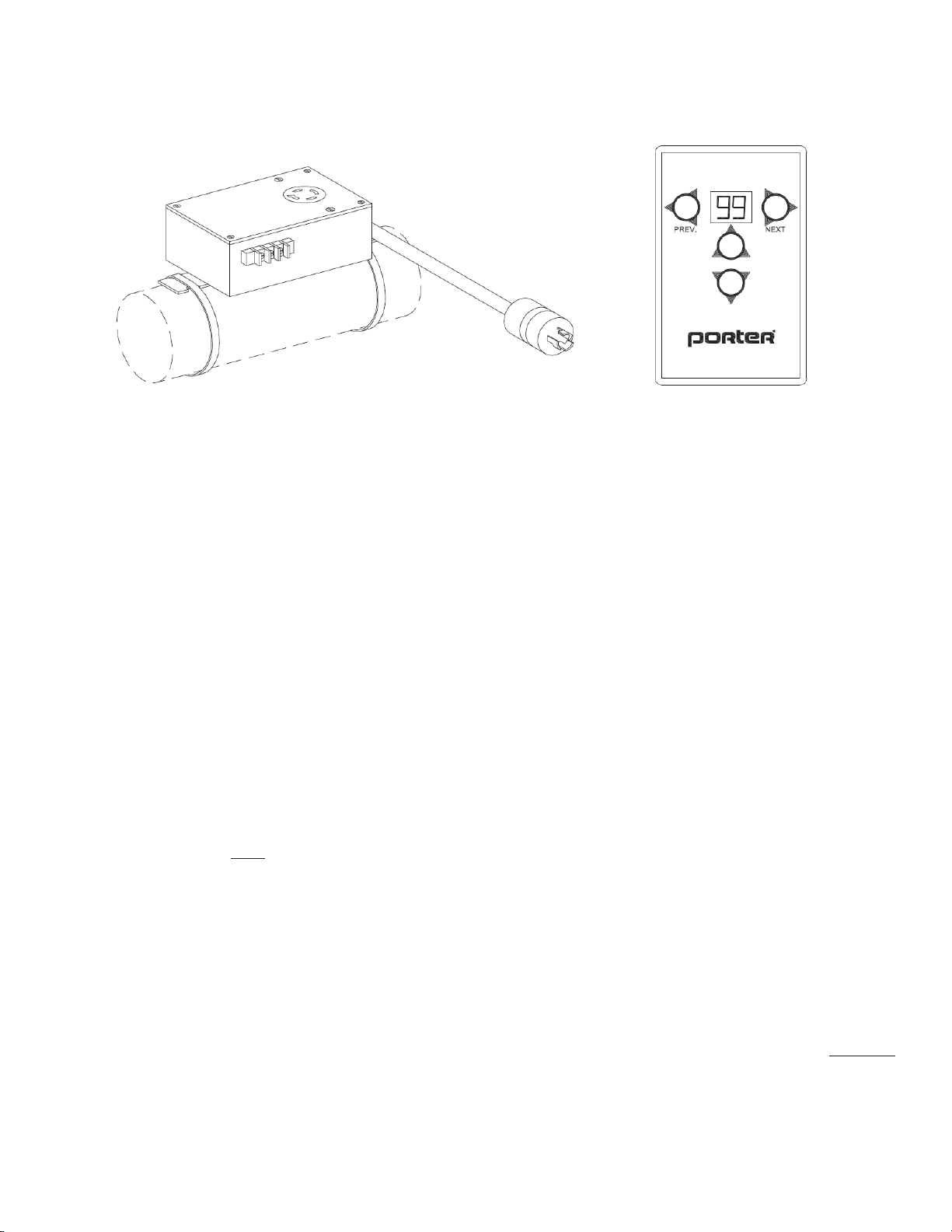
- Check the 9-volt battery in cordless controller.
- Check to ensure that power is available at all winches. A fuse or circuit breaker may have opened the circuit without your
knowledge.
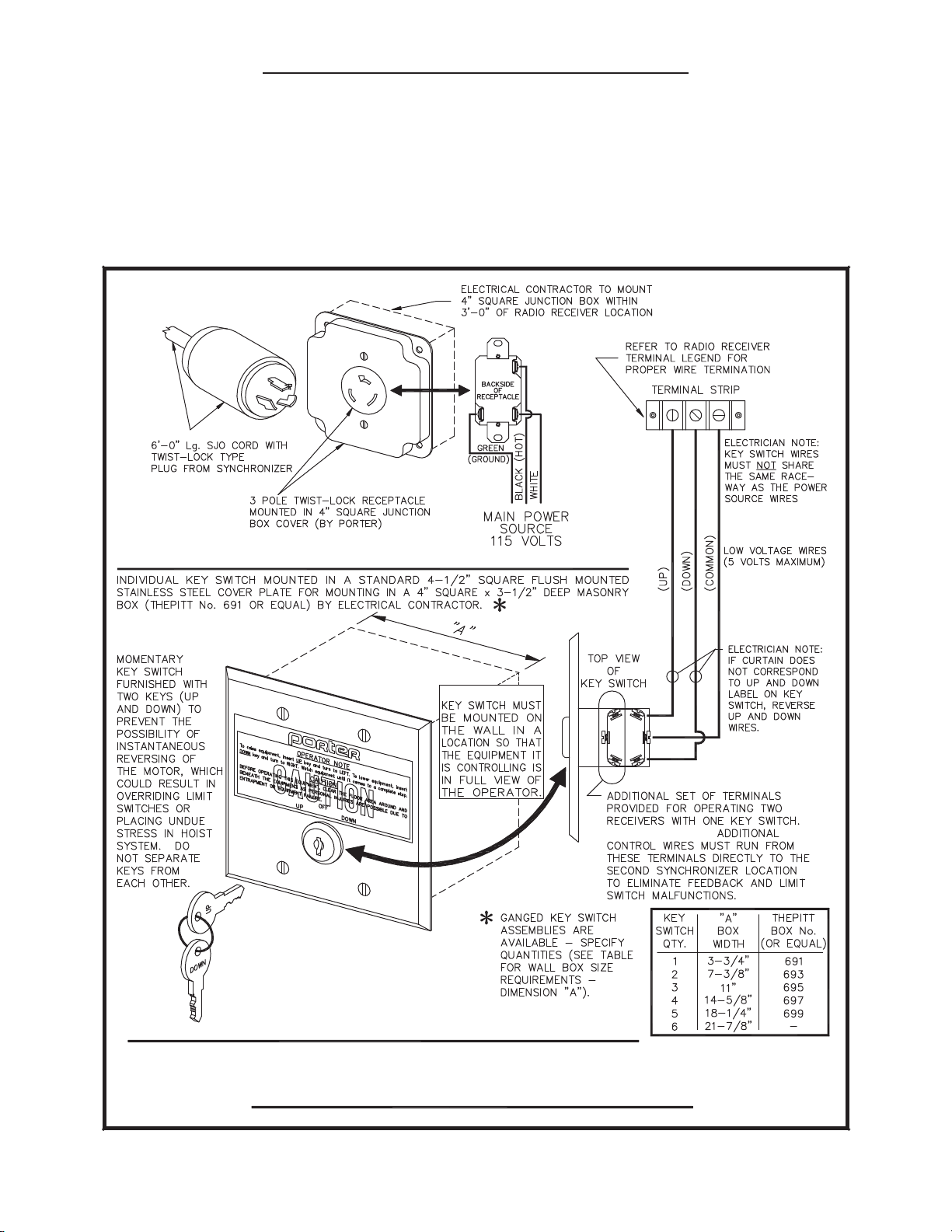
- Check that all plugs are seated firmly in their respective receptacles.
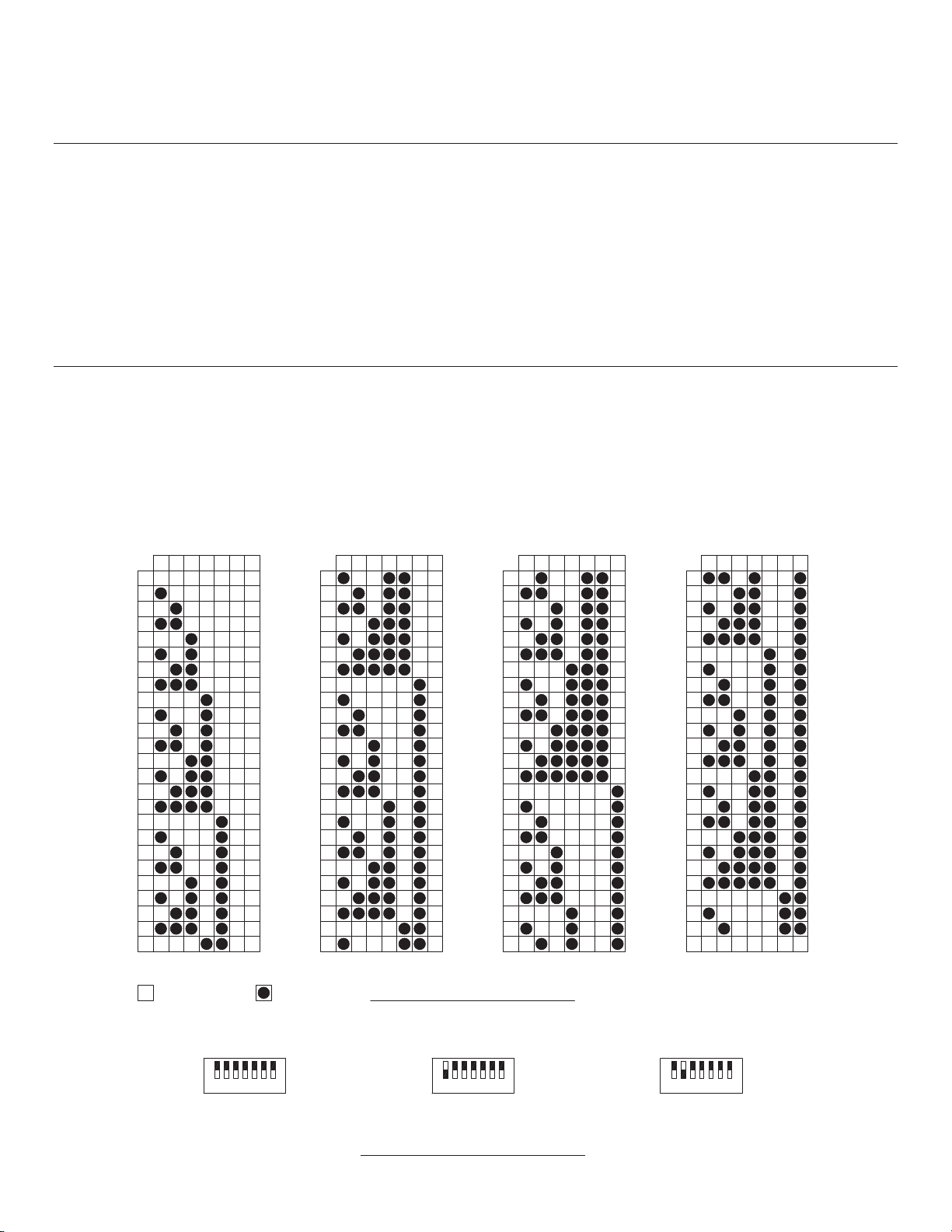
- Verify that the selected equipment to operate corresponds with LED address setting on the Sportsonic£II transmitter.
WARNING
NEVER operate unit with individuals standing on the floor, in bleachers, etc. in the area of the unit being operated.
Operator must stand within full view (within 50 feet) of the unit being operated.
Should any unusual noise or sudden movement of the unit develop during the up or down cycles, halt operation immediately until
unit is checked by a trained technician, and the problem has been corrected.
Cordless controller must always be in the possession of a responsible, trained adult aware of the possible structural damage or
injuries that may occur as the result of improper operation or malfunction.
LIMITED 1-YEAR WARRANTY ON SPORTSONIC
£
II PRODUCTS
Porter Athletic warrants Sportsonic£II products to be free from defective material and workmanship for a period of one (1) year from
original date of purchase at retail. Porter Athletic agrees to repair or replace, at its sole discretion, a defective Sportsonic£II product if
returned to Porter Athletic within the warranty period and accompanied by proof of purchase.
If service is required under this warranty:
1. Call or write to Porter Athletic, Inc. for a Return Merchandise Authorization number to be affixed to returned packaging. (This
RMA number will also be your reference number).
2. Return defective unit, postage or freight prepaid, to:
Porter Athletic, Inc.
601 Mercury Drive
Champagin, Illinois 61822
3. Enclose dated proof of purchase.
4. Enclose check or money order for $2.00 to cover handling and return postage.
5. Make sure all return authorization number labels are affixed to all packages being returned.
6. Porter Athletic, Inc. is not responsible for shipping damage. Units to be returned should be packed carefully.
This warranty does not extend to any Sportsonic£II products which have been subject to misuse, neglect, accident, incorrect wiring,
or to use in violation of operating instructions furnished by us, nor other than an authorized service agency or Porter Athletic factory.
This warranty does not cover any incidental or consequential damages and is in lieu of all other warranties expressed or implied, and
no representative or person is authorized to assume for us any other liability in connection with the sale or our products.
Some states do not allow limitations on how long an implied warranty lasts, and/or the exclusion or limitation of incidental or
consequential damages, so the above limitations or exclusions may not apply to you. This warranty gives you specific rights, and you
may also have other rights, which vary from state to state.
If you have any questions, please call our Customer Service Department at (800) 637-3090.

11
THE OWNER OF THIS EQUIPMENT MUST SAVE THESE
INSTRUCTIONS FOR FUTURE REFERENCE,
AND TO ORDER REPLACEMENT PARTS

12
Porter Athletic Equipment Company
601 Mercury Drive, Champaign, IL U.S.A., 61822
www.porterathletic.com
(888) 277-7778
THIS WARNING IS GIVEN IN COMPLIANCE
WITH CALIFORNIA’S PROPOSITION 65:
WARNING
This product contains chemicals known to the
State of California to cause cancer, birth defects
or other reproductive harm.
WARNING: Cancer and Reproductive Harm –
For more information go to www.p65warnings.ca.gov
F
This manual suits for next models
2
Table of contents
Popular Remote Control manuals by other brands

Daikin
Daikin OM-GS02-1011 operating manual

Proxi
Proxi gate user manual

smart & green
smart & green PEBBLE 1 user manual

Norman
Norman SmartDial user manual

Mitsubishi Electric
Mitsubishi Electric Mr.Slim PAR-30MAA installation manual

Universal Remote Control
Universal Remote Control UR2-DTA operating instructions