Portfolio 00689 User manual

19
ITEM #0810817
MODEL #00689
Español p. 9
Serial Number Purchase Date
Questions, problems, missing parts? Before returning to your retailer, call our customer
service department at 1-800-643-0067, 8 a.m. - 6 p.m., EST, Monday - Thursday,
8 a.m.-5 p.m., EST, Friday.
BM1910
ATTACH YOUR RECEIPT HERE
ARTÍCULO
MODELO #00689
Fecha de compra
¿Preguntas, problemas, piezas faltantes? Antes de volver a la tienda, llame a nuestro
Departamento de Servicio al Cliente al 1-800-643-0067 de lunes a jueves de 8 a.m. a
6 p.m., y los viernes de 8 a.m. a 5 p.m., hora estándar del Este.
ADJUNTE SU RECIBO AQUÍ
Número de serie
200-WATT
POWER PACK
BLOQUE DE ALIMENTACIÓN
DE 200 VATIOS
#0810817
PORTFOLIO®and PORTFOLIO & Design™ are
trademarks or registered trademark of LF, LLC.
All rights reserved.
PORTFOLIO®y PORTFOLIO & Design™ son
marcas o marcas registradas de LF, LLC. Todos
los derechos reservados.

32
PACKAGE CONTENTS
PART DESCRIPTION QUANTITY
ATransformer 1
A
This transformer has a 200-watt circuit that powers up to 200 watts of light. To determine
the maximum number of fixtures that can be safely connected to this transformer, add the individual
wattage of all the fixtures. The total wattage of the fixtures must not exceed 200 watts output capacity.
CALCULATING LIGHTING CAPACITY
HARDWARE CONTENTS (shown actual size)
AA BB CC
Mounting Template
(not actual size)
Qty. 1
Anchor
Qty. 2
Phillips Screw
Qty. 2
SAFETY INFORM ATION
NOTE
This equipment has been tested and found to comply with the limits for a Class B digital device,
pursuant to Part 15 of the FCC Rules. These limits are designed to provide reasonable protection
against harmful interference in a residential installation. This equipment generates, uses and can
radiate radio frequency energy and, if not installed and used in accordance with the instructions, may
cause harmful interference to radio communications. However, there is no guarantee that interference
will not occur in a particular
installation. If this equipment does cause harmful interference to radio or
television reception, which can
be determined by turning the equipment off and on, the user is
encouraged to try to correct the interference
by one or more of the following measures: Reorient or
relocate the receiving antenna; Increase the separation between the equipment and receiver;
Connect the equipment into an outlet on a circuit different from that to which the receiver is
connected; Consult the dealer or an experienced radio/TV technician for help.
PREPARATION
Before beginning installation of product, make sure all parts are present. Compare parts with package
contents list and hardware contents list. If any part is missing or damaged, do not attempt to
assemble the product.
Estimated Assembly Time: 30 minutes
SAFETY INFORMATION
WARNING
Please read and understand this entire manual before attempting to operate or install the product.
• The transformer is not suitable for use with submersible luminaries or pumps.
• This transformer is suitable for outdoor use ONLY.
• This transformer is for use with low-voltage landscape lighting systems ONLY.
CAUTION
combination shall be determined by UL or other inspection authorities having jurisdiction.
rosegaragsahcusaeradesolcnenanirosroodni,skceddoownoremrofsnarttnuomTONOD•
crawl spaces.
• DO NOT repair or tamper with cord or plug.
• DO NOT use extension cords.
• DO NOT submerge the transformer in water.
• DO NOT connect two or more transformers together.
• DO NOT use the transformer with a dimmer switch.
• DO NOT install the transformer within 10 ft. of a pool, spa or fountain.
• Transformer MUST be mounted to a structure or a transformer stand in an upright position. DO NOT
lay the transformer on the ground after connecting it to a circuit.
• DO NOT bury the connectors or cables at depth greater than 6 in.
• DO NOT exceed the maximum wattage of the transformer capacity (200 watts).
• ONLY plug the transformer cord into a covered 120-volt Class A Type GFCI (ground fault circuit
interrupter) receptacle with a hooded flush type cover plate marked “WET LOCATION”.
T
ools Required for Assembly (not included): Phillips Screwdriver, Drill, 3/16 in. Drill Bit, and Wire
Strippers.

54
2
AA
BB
3. For low-voltage cable connections, split one end of
the low-voltage cable (not included) approximately
2 in., and strip about 3/4 in. of insulation off each wire.
Twist each side of wire so the copper is not frayed.
3
2 in.
3/4 in.
Note: Using the correct gauge cable is essential for
obtaining proper lighting performance. For use
with SPT-3, SPT-2, underground low energy
circuit outdoor type cable (Minimum 25 in.
length). See chart:
Hardware Used
1
Mounting Template x 1
CC 12 in.
CC
output terminal:
Combined Wattage of all
fixtures Recommended Cable Gauge Using 12V Recommended Cable Length
14 Less than 200 ft
12 Less than 300 ft
Less than 200W
ASSEMBLY INSTRUCTIONS
1. Select location near a 120-volt covered GFCI outlet.
Using mounting template (CC), mark holes for
transformer (A) at desired location.
Note: The mounting template must be minimum 12 in.
off the ground level.
5
A
m
4
4.
5. Lay a length of low-voltage cable in the general area
where the lights are to be installed. Distribute light
fixtures (not included) as evenly as possible along the
low-voltage cable.
Note: The first fixture should be a minimum of 10 ft.
away from the transformer (A).
ASSEMBLY INSTRUCTIONS
10 ft
Hardware Used
Anchor x 2
AA
BB Phillips Screw x 2
2. Drill holes at depth of about 1.2 in. using 3/16 in.
drill bit (not included). Install anchors (AA) and Phillips
screws (BB), leaving enough space for the transformer
(A) to hang on the the screws.
Note: Do not attach transformer (A) to the wall at this
time.
Loosen the terminal screws located on the bottom of the
transformer (A) and insert one of the pre-stripped wires
under the terminal clamping plate and securely tighten
the terminal screw. Repeat this process for the other side
of the wire, inserting it into the second wire terminal.
CAUTION: To reduce the risk of fire, electrical shock or
damage to the transformer (A), ensure there
is no wire insulation under the terminal
clamping plate and the screws connecting
the cable to the transformer terminals are
securely tightened.
A

6 7
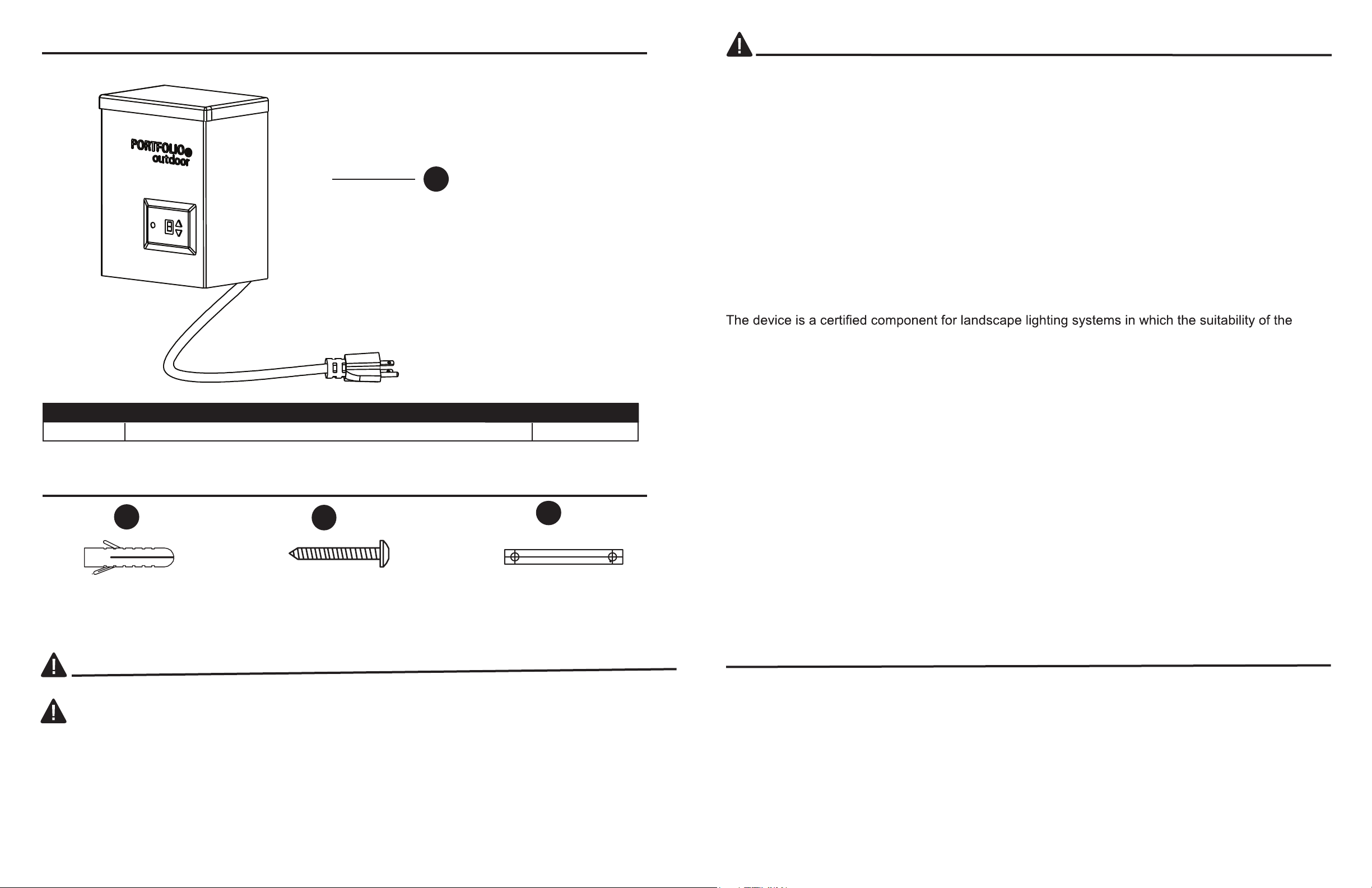
7. Mount the transformer (A) to the wall by hanging the
transformer (A) on the Phillips screws (BB) by means
of the keyhole slots located on the back.
7
OPERATING INSTRUCTIONS
•
Check for overload or short circuits (wires touching) along the cable.
• Check that fixtures are correctly installed on the cable and that there are no short circuits.
Make all repairs before pressing reset button and operating the lighting system.
6 12VAC OUTPUT
ASSEMBLY INSTRUCTIONS
OPERATING INSTRUCTIONS
1. After properly installing the transformer (A), turn on the
electrical source. There are two buttons for operation.
By pressing either button, it will turn to another working
mode. Push either button repeatedly to scroll through
different selections.
“O”--ON (lights stay on until manually turned off).
“A” --AUTO (lights turn on at dusk and off at dawn.)
“1” - “9” -- TIMING (lights turn on at dusk and off after
the selected number of hours.)
CAUTION:
If the manual circuit breaker trips, there is a risk of fire. Reset the unit by pressing the reset
button located on the bottom of the transformer after checking the following:
• Cable is correctly inserted in the cable terminals at the bottom of the transformer and no
wire insulation is under the terminal clamping plate.
If you want to test the photo eye during the day, plug the transformer and cover the photo eye so the
photo eye does not receive any light). Press the setting button to “A”, making sure the photo eye is
completely covered, and your light fixtures will turn on. Uncover the photo eye and your lighting
fixtures will shut off automatically.
Note:
There will be a 30-60 second delay between the lights turning on/off once the photo eye is
covered/uncovered.
TROUBLESHOOTING
1. The transformer is not plugged
in and turned on.
2. Low-voltage cables are not
connected to the transformer
properly.
4.
The transformer is overloaded.
2. Ensure the wires are inserted
properly into the cable terminals
and the terminal screws are
securely tightened.
5. The manual circuit breaker has
tripped.
5. Push the reset button on the
bottom of the transformer to reset
the circuit breaker.
3. Fixture connector is not properly
installed on the low-voltage
cable.
3. Make sure the connect pins
pierce wire insulation and make
proper contact with the wire.
1. Plug the transformer into the
outlet and turn the transformer on.
Fixture doesn’t work
PROBLEM POSSIBLE CAUSE CORRECTIVE ACTION
4. Check the total wattage of all
connected fixtures. Total wattage
must not exceed 200 watts.
Note: If the first light connection does not result in the
light turning on, refer to the troubleshooting section
on page 7. When the transformer (A) is on, an
audible hum may be heard. This is normal and does
not affect the performance of the transformer (A).
6. Plug the transformer into the outlet and turn the
transformer on (refer to operating instructions below).
Connect the light fixtures to the low-voltage cable (not
included) using fixture connectors, and test the system
before finalizing installation. Once testing is completed
and the system is operational, the cable may be covered
with landscape material (mulch, rock, etc.) or buried up to
6 in. deep.
PHOTO EYE
SETTINGS
BUTTON
1
BB
A

8
REPLACEMENT PARTS LIST
AA BB CC
For replacement parts, call our customer service department at 1-800-643-0067, 8 a.m. - 6 p.m.,
EST, Monday - Tursday, 8 a.m. - 5 p.m., Friday.
PART DESCRIPTION PART #
AA
BB
CC
Phillips Screw
Mounting Template
Anchor
Printed in China
WARRANTY
of one year from the date of purchase. If within this period the product is found to be defective in
material or workmanship, the product must be returned, with a copy of the bill of sale as proof of
purchase, to the original place of purchase. The manufacturer will, at its option, repair, replace, or
refund the purchase price to the original purchaser/consumer. This warranty does not cover the
fixture becoming damaged due to misuse, accidental damage, improper handling and/or installation
and specifically excludes liability for direct, incidental or consequential damages. As some states do
not allow exclusions or limitations on an implied warranty, the above exclusions and limitations may
not apply. This warranty gives you specific rights and you may also have other rights that vary from
state to state.
The manufacturer warrants the transformer against defects in materials and workmanship for a period
309100-007900
309100-007900
309100-007900
Table of contents
Other Portfolio Power Pack manuals