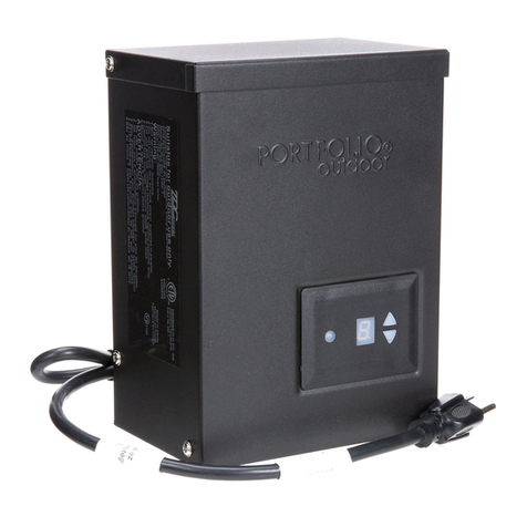
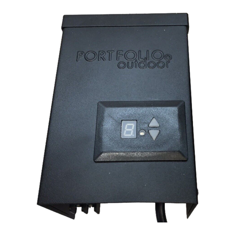
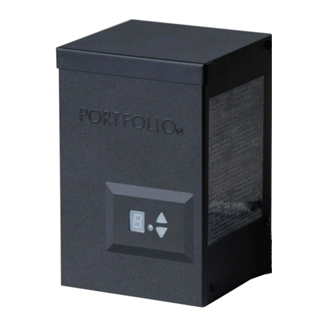
Portfolio 00742 User manual

Portfolio®
is
a registered trademark
of
LF,
LLC. All Rights Reserved.
ATTACH
YOUR
RECEIPT HERE
Serial Number
----
Purchase Date
----
ITEM #0534701
300-WATT
POWER PACK
MODEL#00742
Espanolp. 10
~
Questions, problems, missing parts? Before returning to your retailer, call our customer
f..i;iJ
service department at 1-800-643-0067, 8
a.m.-
6 p.m.,
EST,
Monday-
Thursday,
8 a.m.-5 p.m.,
EST,
Friday.
EB15301 Lowes.
co
m/portfol
io
1

PACKAGE CONTENTS
-·
PART DESCRIPTION QUANTITY
A Power Pack 1
B Fiber Optic Cable 1
HARDWARE CONTENTS (shown actual size)
Fiber Optic Cable
Holder
Qty.
1
<:::::
J
M3.5 Anchor
Qty.
1
M5 Anchor
Qty.
2
<(I
I
\\Ill
\II
I
\II
IC]
M3.5 x 20
mm
Screw
Qty.
1
~\\\\\\\\\\\\\\\\\~
lrH$7-----------~$~1
M5 x 35
mm
Screw Mounting Template
(not actual size)
Qty.
2
Qty.
1
Lowes.com/portfolio
2

A SAFETY INFORMATION
Please read and understand this entire manual before attempting to operate or install the product.
A
wARNING
• This power pack
is
for use with low-voltage landscape lighting systems ONLY.
• This power pack
is
suitable for outdoor use ONLY.
• The power pack is suitable for use with submersible luminaries or pumps.
• Do NOT mount power pack
on
wood decks, indoors or
in
an enclosed area such as garages or crawl
spaces.
•
DO
NOT repair or tamper with cord or plug.
•
DO
NOT use extension cords.
•
DO
NOT submerge the power pack
in
water.
•
DO
NOT connect two or more power packs together.
•
DO
NOT use the power pack with a dimmer switch.
•
DO
NOT install the power pack within
10ft.
of a pool, spa or fountain.
• Power pack MUST be mounted to a structure or a power pack stand
in
an upright position. Do NOT
lay the power pack on the ground after connecting
it
to a circuit.
•
DO
NOT bury the connectors or cables at depth greater than 6
in.
• ONLY plug the power pack cord into a covered 120-volt Class A Type GFCI (ground fault circuit
interrupter) receptacle with a hooded flush type cover plate marked "WET LOCATION".
CAUTION
The device is a certified component for landscape lighting systems
in
which the suitability
of
the
combination shall be determined by UL or other inspection authorities having jurisdiction.
CALCULATING LIGHTING CAPACITY
This power pack has (2) 150-watt circuits that power up to 300 watts of light. To determine the
maximum number of fixtures that can be safely connected to this power pack, add the individual
wattage of
all
the fixtures. The total wattage of the fixtures must not exceed 150 watts for each terminal
output capacity.
NOTE
This equipment has been tested and found to comply with the limits for a Class B digital device,
pursuant to Part 15 of the FCC Rules. These limits are designed to provide reasonable protection
against harmful interference
in
a residential installation. This equipment generates, uses and can
radiate radio frequency energy and, if not installed and used
in
accordance with the instructions, may
cause harmful interference to radio communications. However, there
is
no guarantee that interference
will not occur
in
a particular installation. If this equipment does cause harmful interference to radio or
television reception, which can be determined by turning the equipment off and
on,
the user is
encouraged to try to correct the interference by one or more of the following measures: Reorient or
relocate the receiving antenna; Increase the separation between the equipment and receiver; Connect
the equipment into an outlet
on
a circuit different from that to which the receiver is connected; Consult
the dealer or an experienced radio/TV technician for help.
PREPARATION
Before beginning installation of product, make sure all parts are present. Compare parts with package
contents list and hardware contents list. If any part
is
missing or damaged, do not attempt to
assemble the product.
Estimated
Assembly
Time: 30 minutes
Tools Required for Assembly (not included): Phillips Screwdriver, Drill, 3/16
in.
Drill
Bit,
and Wire
Strippers.
Lowes.
co
m/portfol
io
3
ASSEMBLY
INSTRUCTIONS
1.
Select location near a 120-volt covered GFCI outlet.
Using mounting template (DD), mark holes for
power pack (A) at desired location.
Note: The mounting template must be minimum 12
in.
off the ground level.
Hardware Used
~
Mounting Template ll-f$tt--------ti$ft-ll x 1
2.
Drill holes at depth
of
about 1.2
in.
using 3/16
in.
drill bit (not included). Install M5 anchors (BB) and
M5 x 35 mm screws (CC), leaving enough space for
the power pack (A) to hang on the screws.
Note: Do not attach power pack (A) to the wall at this
time.
Hardware Used
ID
M5 Anchor
~
x2
0 M5 x 35 mm Screw (\\\\\\"\\\\\\\\1\ID
x2
3.
For low-voltage cable connections, split one end
of
the low-voltage cable (not included) approximately
2
in.,
and strip about 3/4
in.
of
insulation off each wire.
Twist each side
of
wire so the copper
is
not frayed.
Note: Using the correct gauge cable is essential for
obtaining proper lighting performance. For use
with SPT-3, SPT-2, underground low energy
circuit outdoor type cable (Minimum 25
in.
length). See chart:
4
12
in.
2
in.
Lowes.
co
m/portfol
io

ASSEMBLY INSTRUCTIONS
Recommended
installation
configurations
for
each
output terminal:
Combined Wattage
of
all Recommended Cable Using
12V
Recommended Cable Length
fixtures Gauge
Less than 2 X 16
300W
(2
X 150W) 2 X 14
2 X 12
4.
Loosen the terminaI screws located on the bottom of the
power pack (A) and insert one
of
the pre-stripped wires
under the terminal clamping plate and securely tighten
the terminal screw. Repeat this process for the other side
of the wire, inserting it into the second wire terminal.
CAUTION: To reduce the risk
of
fire, electrical shock
or
damage to the power pack (A), ensure there
is
no wire insulation under the terminal clamping
plate and the screws connecting the cable to
the power pack terminals are securely
tightened.
5.
Lay a length
of
low-voltage cable
in
the general area
where the lights are to be installed. Distribute light
fixtures (not included) as evenly as possible along the
low-voltage cable.
Note: The first fixture should be a minimum
of
10ft.
away from the power pack (A).
5
2 x Less than 150 ft
2 x Less than 250 ft
2 x Less than 350 ft
•
10ft
0\
• •
Lowes.com/portfolio

ASSEMBLY
INSTRUCTIONS
6.
Plug the power pack into the outlet and turn the
power pack
on
(refer
to
operating instructions below).
Connect the light fixtures to the low-voltage cable (not
included) using fixture connectors, and test the system
before finalizing installation. Once testing
is
completed
and the system
is
operational, the cable may be covered
with landscape material (mulch, rock, etc.) or buried up to
6
in.
deep.
Note: If the first light connection does not result
in
the
light turning
on,
refer to the troubleshooting section
on
page
8.
When the power pack (A)
is
on,
an
audible hum may
be
heard. This
is
normal and does
not affect the performance of the power pack
(A).
7.
Mount the power pack (A) to the wall by hanging the
power pack (A)
on
the M5 x 35
mm
screws (CC) by
means of the keyhole slots located
on
the back.
6
0
Lowes.
co
m/portfol
io

ASSEMBLY
INSTRUCTIONS
8.
When
selecting
a
location
for
the
fiber
optic
cable
(B),
make sure
it
will receive direct sunlight.
DO
NOT
mount
the fiber optic cable (B) where
it
could sense artificial
light, as that might cause the lighting system to shut off
unexpectedly. Drill hole at depth of about 0.8
in.
using
a 3/16
in.
drill bit at desired location
on
an outside wall
and insert M3.5 anchor (EE). Secure fiber optic cable
holder (AA) by inserting M3.5 x 20
mm
screw (FF)
through the fiber optic cable holder (AA) and into the
M3.5 anchor (EE).
Hardware Used
Fiber Optic Cable
,&
Holder
~
X 1
M3.5 Anchor c: : : : : J X 1
M3.5 x 20
mm
Screw
<{\\\\\\\1\\\\\\IIJ
X 1
9.
Insert
fiber
optic
cable
(B)
into
the
photo eye socket
on
the bottom of the power pack (A). Push
in
firmly
until you hear a "click". Make sure the fiber optic cable (B)
is
never crimped
in
any way.
If you want to test the photo eye during the day, plug the
power pack (A) into a GFCI outlet and cover the end of
the fiber optic cable (B) with the preassembled black
plastic cover so the end of the fiber optic cable does not
receive any light. Press the power pack setting button
to
"A".
The light fixtures will turn
on.
Uncover the end of
the fiber optic cable (B) and the lights should shut off
automatically.
Note: There will be a 30-60 second delay between the
lights turning on/off once the end of the fiber optic
cable (B)
is
covered/uncovered.
7
Photo Eye Socket
Black Plastic
Cover
Lowes.com/portfolio

OPERATING INSTRUCTIONS
1.
After properly installing the power pack
(A),
turn
on
the
electrical source. There are two buttons for operation.
By pressing either button,
it
will turn to another working
mode. Push either button repeatedly to scroll through
different selections.
"0"
--ON (lights stay
on
until manually turned off).
"A"
--AUTO (lights turn
on
at dusk and off at dawn.)
"1"-
"9"
--TIMING (lights turn
on
at dusk and off after
the selected number of hours.)
ll
Hour
2 2 Hour
3 3 Hour
"'4
Hour
S 5 Hour
6 6 Hour
1 7 Hour
B8 Hour
9 9 Hour
R
Auto
On/Off
nDusk-to-Dawnn
1C11
Manual
On/Off
CAUTION: If the manual circuit breaker trips, there
is
a risk of fire. Reset the unit by pressing the reset
button located
on
the bottom of the power pack after checking the following:
• Cable
is
correctly inserted
in
the cable terminals at the bottom of the power pack and no
wire insulation
is
under the terminal clamping plate.
• Check for overload or short circuits (wires touching) along the cable.
• Check that fixtures are correctly installed
on
the cable and that there are no short circuits.
Make all repairs before pressing reset button and operating the lighting system.
TROUBLESHOOTING
PROBLEM POSSIBLE CAUSE CORRECTIVE ACTION
Fixture doesn't work
1. The power pack
is
not plugged
in
and turned
on.
2.
Low-voltage cables are not
connected to the power pack
properly.
3.
Fixture connector
is
not properly
installed
on
the low-voltage
cable.
4.
The power pack
is
overloaded.
5.
The manual circuit breaker has
tripped.
8
1.
Plug the power pack into the
outlet and turn the power pack
on.
2.
Ensure the wires are inserted
properly into the cable terminals
and the terminaI screws are
securely tightened.
3.
Make sure the connect pins
pierce wire insulation and make
proper contact with the wire.
4.
Check the total wattage of all
connected fixtures. Total wattage
must not exceed 150 watts per
terminal output capacity.
5.
Push the reset button
on
the
bottom of the power pack to reset
the circuit breaker.
Lowes.com/portfolio

WARRANTY
The manufacturer warrants the power pack against defects
in
materials and workmanship for a period
of
one year from the date
of
purchase. If within this period the product
is
found to be defective
in
material
or
workmanship, the product must be returned, with a copy of the bill of sale as proof
of
purchase, to the original place
of
purchase. The manufacturer will, at its option, repair, replace,
or
refund the purchase price to the original purchaser/consumer. This warranty does not cover the
fixture becoming damaged due to misuse, accidental damage, improper handling and/or installation
and specifically excludes liability for direct, incidental
or
consequential damages. As some states do
not allow exclusions
or
limitations on an implied warranty, the above exclusions and limitations may
not apply. This warranty gives you specific rights and you may also have other rights that vary from
state to state.
REPLACEMENT PARTS LIST
For replacement parts, call our customer service department at 1-800-643-0067, 8
a.m.-
6 p.m.,
EST,
Monday-
Tursday, 8 a.m. - 5 p.m., Friday. G
Fiber
AA
Fiber Optic Cable Holder
BB M5 Anchor
CC M5 x 35 mm Screw
DD
EE
Cb
FF M3.5 x 20 mm Screw
II
II
9
e
iJ
e
c:::::::::l
~
. ~
~
CI\\NIUN\1\\\I~
<!lllllllllllll
Printed
in
China
Portfolio® is a registered
trademark
of
LF,
LLC.
All rights reserved.
Lowes.com/portfolio

ARTICULO #0534701
300
VA
TIOS DE POTENCIA
Portfolio®
es
una marca registrada de
LF,
LLC.Todos los derechos reservados.
ADJUNTE SU RECIBO AQUf
Numero de serie Fecha de compra
----
PAQUETE
MODELO #00742
®l_Preguntas, problemas, piezas faltantes? Antes de volver a
Ia
tienda, llame a nuestro
Departamento de Servicio
al
Cliente al1-800-643-0067 de lunes a jueves de 8 a.m. a
6 p.m., y los viernes de 8 a.m. a 5 p.m., hora estandar del Este.
Lowes.com/portfolio
10

CONTENIDO DEL PAQUETE
-·
PART DESCRIPTION
A Bloque de alimentacion
B Cable de fibra
ADITAMENTOS (se muestran
en
tamano real)
Soporte para cable
de fibra optica
Cant. 1
<:::::
J
Ancla de
expansion
M3.5
Cant. 1
Ancla de
expansion
M5
Cant. 2
<(I
I
\11\\1
II\IllI
(Jj
Tornillo
M3.5
x20
mm
Cant. 1
<(\\\\\\\\\\\\\\\\\\
~
11
Tornillo
M5x35
mm
Cant. 2
G
QUANTITY
1
1
I$
$1
Plantilla para montaje
(nose
muestra en
tamano real)
Cant. 1
Lowes.com/portfolio

A INSTRUCCIONES DE SEGURIDAD
Lea y comprenda completamente este manual antes de intentar usar o instalar
el
producto.
A ADVERTENCIA
• Este bloque de alimentaci6n es SOLO para usa con sistemas de iluminaci6n para
el
jardfn de bajo
voltaje. ,
• Este bloque de alimentaci6n es adecuado SOLO para usa en exteriores.
•
El
bloque de alimentaci6n es adecuado para
el
usa con luminarias y bombas sumergibles.
• No monte
el
bloque de alimentaci6n en terrazas de madera,
en
interiores o en un area cerrada como
garajes o subsuelos.
• NO repare
ni
modifique
el
cable o
el
enchufe.
• NO utilice extensiones electricas.
• NO sumerja
el
bloque de alimentaci6n en agua.
• NO conecte dos o mas bloque de alimentaci6n
al
mismo tiempo.
• NO utilice
el
bloque de alimentaci6n con un atenuador de intensidad.
• NO instale
el
bloque de alimentaci6n
en
un radio de 3.05 m de una piscina, un spa o una fuente.
•
El
bloque de alimentacion DEBE montarse en una estructura o una base para bloque de alimentacion
en una posicion vertical. NO coloque
el
bloque de alimentacion en
el
suelo luego de conectarlo a
un circuito.
• NO entierre los conectores
ni
los cables a una profundidad mayor que 15,24
em.
• SOLAMENTE enchufe
el
cable del bloque de alimentacion en un tomacorriente de 120 voltios
Clase A Tipo GFCI (interrupter de circuito par falla a tierra) con una placa de cubierta tipo capuchon
al
ras con
Ia
inscripcion" PARA LUGAR HUMEDO".
PRECAUCION:
El
dispositive es un componente certificado del sistema de iluminaci6n para el jardin donde
Ia
aptitud
de
Ia
combinacion sera determinada par UL o par otras autoridades de inspeccion que tengan
jurisdiccion.
CALCULO
DE
LA
CAPACIDAD DE ILUMINACION
Este bloque de alimentacion tiene (2) circuitos de 150 vatios que proporcionan hasta 300 vatios de
iluminacion. Para determinar
Ia
cantidad maxima de lamparas que pueden conectarse de manera
segura a este bloque de alimentacion, sume los vatajes individuales de todas las lamparas.
El
vataje
total de las lamparas no debe superar los 150 vatios de
Ia
capacidad de salida de cada terminal.
NOTA: Este equipo ha sido probado y se ha verificado que cumple con los lfmites para un dispositive
digital clase
B,
conforme a
Ia
seccion 15 de las reglas de
Ia
FCC. Estos lfmites se han disenado para
proporcionar una proteccion razonable contra
Ia
interferencia perjudicial en una instalacion residencial.
Este equipo genera, utiliza y puede irradiar energfa de radiofrecuencia
y,
si
no se instala y se usa de
acuerdo con las instrucciones, puede causar interferencia perjudicial a las comunicaciones de radio.
Sin embargo,
nose
garantiza que
nose
produciran interferencias en una instalacion
en
especial.
Si
este equipo genera una interferencia perjudicial para
Ia
recepcion de radio o television, que se puede
determinar apagando y encendiendo
el
equipo, se recomienda
al
usuario que intente corregir
Ia
interferencia con una o mas de las siguientes medidas: Reoriente o reubique
Ia
antena de recepcion.
Aumente
Ia
separaci6n entre
el
equipo y
el
receptor. Conecte
el
equipo a un tomacorriente de
un
circuito distinto
al
que usa
el
receptor. Solicite ayuda
al
concesionario o a un tecnico con experiencia
en radio/TV.
PREPARACION
Antes de comenzar a instalacion
el
producto, asegurese de tener todas las piezas. Compare las piezas
con
Ia
lista del contenido del paquete y
el
diagrama anterior. No intente ensamblar
el
producto
si
falta
alguna pieza o
siestas
estan danadas. Comunfquese con
el
Departamento de Servicio
al
Cliente para
obtener piezas de repuesto.
Tiempo
aproximado
de
ensamblaje:
30
minutos
Herramientas necesarias para
el
ensamblaje
(nose
incluyen): Destornillador Phillips, taladro, broca
para taladro de 3/16" y pinzas pelacables. Lowes.com/portfolio
12

INSTRUCCIONES DE ENSAMBLAJE
1. Seleccione una ubicaci6n cerca de
un
tomacorriente
con interrupter de puesta a tierra (GFCI, par sus siglas
en ingles) cubierto de 120 voltios. Con
Ia
plantilla de
montaje (DD) marque orificios para
el
bloque de
alimentaci6n
en
Ia
ubicaci6n deseada.
Nota: Debe estar a 30
em
sabre
el
nivel del suelo.
Aditamentos utilizados
~
Plantilla de montaje
18$E:=:=:=:=ii>81
x 1
2.
Taladre orificios a una profundidad de alrededor de
3,05
em
con una broca para taladro de 3/16 pulg (no se
incluye). lnstale las ancla de expansion M5 (BB) y los
tornillo M5 x 35 mm (CC) y deje suficiente espacio para
que
el
bloque de alimentaci6n (A) cuelgue del tornillo.
Nota: No fije
el
bloque de alimentaci6n (A) a
Ia
pared en
este punta.
Aditamentos utilizados
ID
Ancla de expansiOn M5
~
x 2
0 Tornillo M5 x 35
mm
<1\\\\\U\\\\\\\\\\ID x 2
3.
Para
Ia
conexi6n de cables de bajo voltaje, separe
un
extrema del cable de bajo voltaje
(nose
incluye) de
aproximadamente 5,08
em
y pele aproximadamente
1,91
em
del aislamiento de cada cable. Gire cada lado
del cable de modo que
el
cobre no se deshilache.
Nota: Es crucial utilizar
el
calibre de cable correcto para
obtener
el
rendimiento lumfnico apropiado. Para su
usa con cable tipo SPT-3, SPT-2, subterraneo, de
bajo voltaje y para en exteriores. (longitud mfnima
de 7,62 m). Consulte
Ia
tabla.
13
30
em
5,08
em
Lowes.com/portfolio

INSTRUCCIONES
DE
ENSAMBLAJE
Recomendaciones
de
configuraciones
de
instalaci6n para cada terminal de salida:
Vataje combinado de todas Calibre de cable
las lamparas recomendado
2 X 16
Menos que 300 vatios 2 X 14
(150 vatios x 2) 2 X 12
4.
Suelte los tornillos del terminal ubicados en
Ia
parte
inferior del bloque de alimentaci6n (A) e inserte uno de
los cables pelados previamente debajo de
Ia
placa de
sujeci6n del terminal y apriete firmemente
el
tornillo del
terminal. Repita este proceso para
el
otro lado del cable
e insertelo
en
el
segundo terminaI del cable.
PRECAUCION: Para reducir
el
riesgo de incendio,
descarga electrica o dana
al
bloque de alimentaci6n
(A),
asegurese
de que
no
haya aislamiento de cable
debajo de
Ia
placa de sujeci6n del
terminal y que los tornillos que conectan
el
cable a los terminales del bloque de
alimentaci6n esten fuertemente
apretados.
5.
Coloque
un
tramo de cable de bajo voltaje en
el
area
general donde se instalaran las luces. Distribuya los
ensambles de luz
(nose
incluyen)
lomas
parejo que
pueda a
lo
largo del cable de bajo voltaje.
Nota:
La
primera
lam
para debe estara par lo menos
3,05 m de distancia del bloque de alimentaci6n
(A).
14
Usa del largo recomendado
del cable
12
V
2 x Menos que 45,72 m
2 x Menos que 76,2 m
2 x Menos que 106,68 m
•
3,05 m
0\
• •
Lowes.com/portfolio

INSTRUCCIONES
DE
ENSAMBLAJE
6.
Enchufe el bloque de alimentaci6n en
el
tomacorrientes y
encienda el bloque de alimentaci6n (consulte las
instrucciones de operaci6n que aparecen a continuaci6n).
Conecte los ensambles de luz al cable de bajo voltaje (no
se incluyen) con conectores de ensambles y pruebe
el
sistema antes de terminar
Ia
instalaci6n. Una vez que
haya completado
Ia
prueba y el sistema este operacional,
se debe cubrir
el
cable con material de paisajismo
(compuesto organico, roca, etc.) o entierrelo a una
profundidad de 15,24
em.
Nota: Si
Ia
luz
nose
enciende al conectarla par primera
vez, consulte
Ia
secci6n de soluci6n de problemas
en
Ia
pagina 17. Es posible que cuando el
bloque de alimentaci6n (A) esta encendido, se
escuche un zumbido. Esto es normal y no afecta
el
....._
______________
__,
rendimiento del bloque de alimentaci6n (A).
7.
Monte
el
bloque de alimentaci6n (A) en
Ia
pared; para
ella, cuelgue el bloque de alimentaci6n (A) en los
tornillos M5 x 35 mm (CC) mediante las ranuras con
forma de cerradura ubicadas en
Ia
parte posterior.
15
Lowes.com/portfolio

INSTRUCCIONES DE ENSAMBLAJE
8.
AI
seleccionar una ubicacion para el cable
de
fibra optica
con
sensor
fotoelectrico (B), asegurese
de
que
recibira
luz solar directa durante el dfa. NO coloque el cable
de
fibra optica con sensor fotoelectrico (B) donde podrfa
percibir luz artificial, ya
que
esto podrfa provocar
que
el
sistema
de
iluminacion se apague inesperadamente.
Taladre un orificio con una profundidad
de
aproximadamente 2,03
em
con una broca para taladro
de
3/16" en
Ia
ubicacion deseada en
Ia
pared exterior y
coloque un ancla de expansion M3.5 (EE).
Asegure
el
soporte para cable
de
fibra optica (AA), para esto inserte
un tornillo
M3.5
x
20
mm (FF)
par
el soporte para cable
de
fibra optica (AA) y dentro del ancla
de
expansion
M3.5 (EE).
Aditamentos utilizados
Soporte para cable
de
fibra optica
Ancla
de
expansion
Tornillo M3.5 x
20
mm
X 1
<::
::: J X 1
<C\11
\Ill
\Ill
I
11\lj
X 1
9.
lnserte el cable
de
fibra optica con
sensor
fotoelectrico
(B) en el socket del sensor fotoelectrico en
Ia
parte
inferior del bloque
de
alimentacion (A). Empuje con
firmeza hastaofr un clic.
Asegurese
de
que el cable
de
fibra optica (B) con sensor fotoelectrico nunca tenga
pliegues ni este ondulado en ningun modo.
Si desea probar el
sensor
fotoelectrico durante el
dfa, enchufe el bloque
de
alimentacion (A) en un
tomacorriente con interrupter de puesta a tierra
(GFCI, par sus siglas en ingles) y cubra el extrema
del cable
de
fibra optica (B) con
Ia
cubierta negra
de
plastico preensamblada para
que
el extrema del
cable
de
fibra optica (B) no reciba
nada
de
luz.
Presione el baton
de
configuracion del
bloque
de
alimentacion a "A". La lampara se encendera.
Descubra el extrema del cable
de
fibra optica (B);
las lamparas deben apagarse automaticamente.
Portalampara del
sensor fotoeh§ctrico
'\
Cubierta
negra\
de plastico O
Nota: Luego de cubrir o descubrir el extrema del cable de fibra optica (BB), habra un retraso
de
30 a
60
segundos entre el encendido o apagado de las luces.
Lowes.com/portfolio
lfeHife]l[
eJ
16

INSTRUCCIONES
DE
FUNCIONAMIENTO
1. Despues de
Ia
instalaci6n correcta del bloque de
alimentaci6n, active
Ia
fuente electrica. Existen dos
botones de operaci6n. Cada vez que presione algun
bot6n, cambiara a otro modo de funcionamiento.
Presione repetidamente para realizar las diversas
selecciones.
"O":ENCENDIDO (las luces permanecen encendidas
hasta que se apaguen manualmente).
"A":
AUTOMATICO (las luces se encenderan
al
anochecer y se apagaran
al
amanecer mediante
el
cable de fibra 6ptica).
"1"
a
"9":
TEMPORIZADOR (las luces se encenderan
al
atardecer y se apagaran despues de
Ia
cantidad de
horas seleccionadas).
PRECAUCION:
I 1 Hora
2 2 Hora
3 3 Hora
'-1
4 Hora
S 5 Hora
E.
6 Hora
l 7 Hora
8 8 Hora
g 9 Hora
l8J
•
R Encendido I apagado automatico
1\
v
des
de
el
anochecer hasta
el
amanecer
o manual de encendido I apagado
0' bot6n de
configuraci6n
~
Si
el
interrupter de circuito manual se activa, existe riesgo de incendio. Presione
el
bot6n de reinicio
ubicado
en
Ia
parte inferior del bloque de alimentaci6n para reiniciar
el
dispositive y revise
lo
siguiente:
•
El
cable esta insertado correctamente
en
los terminales del cable ubicados en
Ia
parte inferior del
bloque de alimentaci6n y no hay aislamiento de cable debajo de
Ia
placa de sujeci6n del terminal.
• Controle
Ia
sobrecarga o los cortocircuitos (los cables se tocan entre sf) a
lo
largo del cable.
• Controle que las
lam
paras esten correctamente instaladas
en
el
cable y que no haya cortocircuitos.
Haga todas las reparaciones antes de presionar
el
bot6n de reinicio y de operar
el
sistema de
iluminaci6n.
SOLUCION
DE
PROBLEMAS
PROBLEMA CAUSA POSIBLE ACCION CORRECTIVA
La
lampara no funciona
1.
El
bloque de alimentaci6n no
esta enchufado y encendido.
2.
Los cables de bajo voltaje no
estan conectados
al
bloque de alimentaci6n de
forma adecuada.
3.
El
conector de
Ia
lampara no
esta instalado correctamente
en
el
cable de bajo voltaje.
4.
El
bloque de alimentaci6n
esta sobrecargado.
5.
El
interrupter de circuito
manual se activo.
17
1.
Enchufe
el
bloque de alimentaci6n
al
tomacorriente y luego enciendalo.
2.
Asegurese de que los cables esten
insertados de forma correcta en los
terminales de los cables y que los
tornillos de los terminales esten
firmemente apretados.
3.
Asegurese de que las clavijas de
conexi6n atraviesen
el
aislamiento
del cable y esten en contacto con
el
cable de forma adecuada.
4.
Revise
el
vataje total de todas las
lamparas conectadas.
El
vataje total
de
Ia
capacidad de salida de cada
terminaI
no
debe superar los 150
vatios.
5.
Presione
el
bot6n de reinicio ubicado
en
Ia
parte inferior del bloque de
alimentaci6n para reiniciar
el
interrupter de circuito.
Lowes.com/portfolio

GARANTiA
El
fabricante garantiza que este bloque de alimentacion no presentara defectos en los materiales
ni
en
Ia
mana de obra par
un
perfodo de
un
ana a partir de
Ia
fecha de compra.
Si
dentro de este perfodo
el
producto presenta defectos en
el
material o
Ia
mana de obra, se debe devolver
el
producto, junto con
una copia del recibo de venta como prueba de
Ia
compra,
allugar
donde se compro.
El
fabricante, a
su
eleccion, reparara, reemplazara o devolvera
el
manto de
Ia
compra
al
comprador original. Esta garantfa
no cubre danos
en
el
ensamble debido a mal usa, dana accidental, manipulacion o instalacion
inadecuada y/o excluye especfficamente toda responsabilidad par danos directos, accidentales o
resultantes. Debido a que
algunos
estados
no
permiten exclusiones o limitaciones en una garantfa
implfcita, las exclusiones y limitaciones anteriores pueden no aplicarse. Esta garantfa le otorga derechos
especfficos pero podrfa tener tambie otros derechos que varfan segun
el
estado.
LISTA DE PIEZAS DE REPUESTO
Para piezas de repuesto, llame a nuestro Departamento del Servicio
al
Cliente al1-800-643-0067,
de lunes a jueves de 8
a.
m.
a 6
p.
m.
y los viernes de 8
a.
m.
a 5
p.
m.,
hora estan dar del Este.
PIEZA DESCRIPCION
B Cable de fibra
AA
Soporte para cable de fibra optica
BB
Ancla de expansion M5
cc Tornillo M5 x 35
mm
DD
Plantilla para montaje
EE
Ancla de expansion M3
FF
Tornillo M3.5 x 20
mm
PIEZA#
990619-0013BK
3091
00-008000
3091
00-008000
3091
00-008000
3091
00-008000
3091
00-008000
3091
00-008000
18
0
.nuummmm'""'ID
I
Ill
Ill
I
c::::::::l
lmpreso en China
Portfolio
®est
una marca registrada
de
LF,
LLC. Todos los derechos
reservados.
Lowes.com/portfolio
Table of contents
Languages:
Other Portfolio Power Pack manuals