PortKeys BM5IIIWR User manual

Service Hotline: 18820958861
Email: [email protected]om
Website: www.portkeys.com
Company Address:1406, 14th Floor, Block D, Building 3,
Cloud Park, Longgang District, Shenzhen, Guangdong, China
Factory Address: 2nd Floor, Building A, Jingjiang Industrial Park,
NO.101, Shangwei Road, Longhua District, Shenzhen,Guangdong, China

Warning
Warnings
6.1
Function Interface
Function Interface Gesture Switching
Function Introduction
Custom Function Keys Settings
Basic Operation
2.1
2.2
2.3
2.4
Camera Control Interface Gesture Switching
Camera Model Settings
Bluetooth Connection
Function Usage
WIFI Connection
Camera Control Interface
4.1
4.2
4.3
4.4
4.5
Motor Control Interface Gesture Switching
Motor Control
Motor Control Interface
5.1
5.2
Product Information
Product Introduction
Packing List
Basic Parameters
Signal Specifications
1.2
1.3
1.4
1.1
Settings Interface Gesture Switching
Image Settings
Image and Menu Flip Settings
System Settings
Volume Settings
Version Settings
Settings Interface
3.1
3.2
3.3
3.5
LUT Output Settings 3.4
3.6
3.7
3.8
3D LUT Settings
3.9
Signal Source Settings
Contents

Product Information 1.1
5.5”91.4MM
145.4MM
Power
Switch
HDMI
Input
Audio
Headphone
Output
1/4" Threaded Insert
USB Upgrade
Port
Camera Control
Interface
7-24V Power Terminal
Focus Follow
Control Interface Battery Plate
Lock
2.4GHz
Antenna
SDI Input/
Output
Sliding Menu
EXIT / Long press for 3 seconds
to switch the state of touch control
IndicatorCustom Function Keys
37.8MM
Operating temperature range: 0 ℃~ 40 ℃
Product Introduction

Product Information 1.2
Packing List
BM5IIIWR Monitor X1
LANC Control Cable 0.4m X1
TYPE-C Control Cable 0.4m X1
Warm Prompt Card X1
Safety Box X1
L-Type Antenna X2
Power Cord 1m (Aviation
Connector - D-TAP) X1
Power Cord 0.4m (Aviation
Connector - DC) X1
U Disk(Manual,3D LUTs,
Firmware Inside) X1

Product Information 1.3
Size
Dimension
Viewing Angle
Brightness
Resolution
Contrast Ratio
Weight
Color
Backlight
Material
Input Voltage
Max Power
Signal Input
Signal Output
Headphone
Menu Language
Power Input / Output
Signal Conversion
Camera Control Interface
Motor Control Interface
Support Battery Model
Upgrade Firmware / Load LUT
Fan
Antenna
5.5"
145.4x91.4x37.8mm
178°H/178°V
2200nit
1920x1080
1000:1
383g
10bit(8+2 FRC)
WLED
Aluminum Alloy + Toughened Glass
DC 7~24V
14W
3G SDI、HDMI
3G SDI
Output
简体中文/English
4pin Aviation Connector
HDMI IN to SDI OUT
CAMERA REMOTE
Focus Puller
SONY NP-F970/F960/F750/F550
USB-A
Yes
2.4G
Basic Parameters

Supported input resolution and frame rate
1920×[email protected],24Hz,25Hz,29.97Hz,30Hz,50Hz,59.94Hz,60Hz
1920×[email protected],24Hz,25Hz,29.97Hz,30Hz
1920×1080i@50Hz,59.94Hz,60Hz
1280×720p@50Hz,59.94Hz,60Hz
720×576p&720×576i@50Hz
720×480p&720×480i@50Hz,59.94Hz,60Hz
HDMI Signal
Supported input/output resolution and frame rate
1920×1080p@50fps,59.94fps,60fps
1920×1080p@50Hz,59.94Hz,60Hz YUV422
1920×[email protected],24Hz,25Hz,29.94Hz,30Hz YUV444/YUV422/RGB444
1920×[email protected],24Hz,25Hz,29.97Hz,30Hz YUV444/YUV422/RGB444
1920×1080i@50Hz,59.94Hz,60Hz YUV444/YUV422/RGB444
1280×720p@50Hz,59.94Hz,60Hz YUV444/YUV422/RGB444
720×[email protected] YUV422
720×576i@50Hz YUV422
SDI Signal
Signal Specifications
Product Information 1.4

Function Interface 2.1
(the function setting interface)
Swipe right on any interface to adjust to
the function setting interface;
[Function interface gesture switching]
Off Low
HDMI 18.1V
50
Contrast
50
Brightness
50 30
Sharpness Tint
50
Chroma

Function Interface 2.2
[Function Introduction]
1. Software Function;
2. Add Function Icon;
3. Switch HDMI/SDI Signal;
4. 3D LUT ON/OFF;
5. Screen Brightness (1-10);
6. Fan Strength (Low /High);
7. Battery Level;
Off Low
HDMI 18.1V
43
1
2
5 6 7

Function Interface 2.3
2
Check
Field
HDR(HLG) 3D LUT
Image
Crop
Guides Cross Hair Grids Peaking False Color
Zebra UnderScan VectorScop Luma
Histogram
RGB
Histogram
RGB
Waveform
Waveform
(All)
Time Code Audio
Meters
Luma
Waveform
Image
Capture
Image
Overlay
6. After F keys setting is completed, F1-F4 keys on the monitor
can be used to turn on/off the functions(Picture 4);
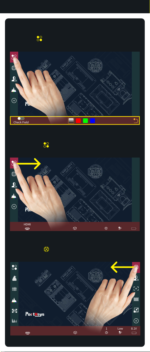
5. The first four functions are F1-F4 shortcut functions by
default. You can swipe left/ right to enter the fucntion
menu to change the custom functions(Picture 3);
(Picture 2)
1. Click “ ”add shortcut functions to the left and right sides;
If the function icons on the left and right have been added
(Picture 2);You can swipe down in the shortcut function title
area to continue adding.
2. Select the function icon to replace;
3. Select the function icon and click“ ”to delete;
4. “ ”Return key;
(Picture 3)
[Custom Function Keys Settings]
1
(Picture 1)
34
Peaking Sensitivity
Colour
Style
6
Grayscale Level
100%
5
Check
Field
HDR(HLG) 3D LUT
Image
Crop
Guides Cross Hair Grids Peaking False Color
Zebra UnderScan VectorScop Luma
Histogram
RGB
Histogram
RGB
Waveform
Waveform
(All)
Time Code Audio
Meters
Luma
Waveform
Image
Capture
Image
Overlay
2
6
(Picture 4)

Function Interface 2.4
Swipe the icon“ ”to the left and enter the function menu,
you could replace or delete functions(Picture 7);
(Picture 7)
Off Low
HDMI 18.1V
Long press “ ”,the function parameter setting shows at the
bottom(Picture 5);
(Picture 5)
Check Field
Swipe the icon“ ”to the right and enter the function menu,
you could replace or delete functions(Picture 6);
(Picture 6)
Off Low
HDMI 18.1V
[Basic Operation]

Setting Interface 3.1
Swipe left on any interface to adjust to
the system settings interface;
( the system settings interface)
[Settings interface gesture switching]
50
Contrast
50
Brightness
50 30
Sharpness Tint
50
Chroma
Off Low
HDMI 18.1V

Setting Interface 3.2
2
50
Contrast
50
Brightness
50 30
Sharpness Tint
50
Chroma
2
[Image Settings]
1. Click “ ” ;
2. Parameter setting information;
3. Parameter setting information(Next page );
4. Display the number of the page of Image parameter setting;
Swipe left or right in the bottom information area to switch
pages;
1
1.00X 1
Backlight
6500K
Color TemperatureAnamorphic
3
4

Setting Interface 3.3
1
1
HDMI SDI
2
1. Click “ ” ;
2. Signal source setup information;
[Signal Source Settings]

Setting Interface 3.4
1. Click “ ” ;
2. LUT output and 1080P->I and other setting information;
2
[LUT Output Settings]
SDI
Output 1080P->ILoad LUT Out 3G LevelA/B Out
Auto
1

Setting Interface 3.5
1
2
1
Display Flip Mode V FlipH Flip Osd Flip Mode H Flip V Flip
[Image and Menu Flip Settings]
1. Click “ ” ;
2. Image and menu flip setting information;

设置界面 3.6
1. Click “ ”;
2. System parameter setting information;
3. System parameter setting information(Next page);
1
2
1
English
OSD-Language System Reset
Low
OSD-Transparancy Fan
Low
Detect Data Source
After LUT
[System Setting]
1
3
1
Screen Color Cali.. Gesture ZoomingBlack Level

Setting Interface 3.7
Reset LUTStored from USB USB Looks
3D LUT
2
1
[3D LUT Setting]
1. Click“ ”;
2. 3D LUT setting information;

Setting Interface 3.8
2
1
Volume
6
1. Click“ ”;
2. Volume information;
[Volume Setting]

Setting Interface 3.9
1. Click“ ”;
2. View version information and upgrades;
[Version Setting]
Update(USB)
2
BM5-V3WR.15.43.C18.B23
Version Information
1

Camera Control Interface 4.1
[Camera control interface gesture
switching]
Swipe down on any interface can be adjusted to
the camera control settings interface;
(the camera control settings interface)
CxxxLong10toRec..
Z CAM E2(LANC)
Canon(LANC)BMPCC(LANC)BMPCC(BLE)Wi-Fi / USB
Off Low
HDMI 18.1V
Table of contents
Other PortKeys Camera Accessories manuals