Porvair Sciences MiniVap Gemini User manual

Page 1
V 1.1 –August 2017
U s e r I n s t r u c t i o n M a n u a l
U s e r I n s t r u c t i o n
M a n u a l

Page 2
V 1.1 –August 2017
U s e r I n s t r u c t i o n M a n u a l
The information in this user guide, including any apparatus, methods, techniques and concepts
described herein, are the property of Porvair Sciences Limited or its Licensees and may not be
copied, disclosed or used for any purpose not expressly authorised by its owners thereof.
This document is for information only; the manufacturer accepts no liability for errors contained
herein or for incidental or consequential damages with the furnishing, performance or use of
this material.
Since Porvair Sciences Limited, constantly strives to improve all of its products, we reserve the
right to modify equipment and user guides without prior notice.
No part of this guide may be reproduced in any form or by any means (including storage and
retrieval or translation into a foreign language) without the prior agreement and written consent
of Porvair Sciences Limited.
Copyright © 2003 –2015 Porvair Sciences Limited
All Rights Reserved
Specifications subject to change without notice. E&OE.

Page 3
V 1.1 –August 2017
U s e r I n s t r u c t i o n M a n u a l
Contents
Introduction Page 4
Installation Page 5
Microplate Requirements Page 5
Health & Safety Page 6
Specifications & System Requirements Page 8
What’s in the Box Page 9
Product Overview Page 10
Connecting the Gas & Power Supply Page 12
Fitting / Changing Needle Head Page 13
Operating Instructions Page 16
Adjusting the Platform Page 17
Temperature Setting Page 18
Setting Inlet Operating Pressure Page 21
Setting System Gas Flow Page 21
Sample Concentration Using MiniVap Gemini Page 22
Over Temperature Thermal Cut –Out Page 22
Cleaning Information Page 23
Changing Mains Protection Fuse Page 26
Fault Finding Page 27
Identifying Your MiniVap Gemini Page 28
Declaration of Conformity Page 29
Spare Parts & Accessories Page 30
Warranty & Returns Page 31

Page 4
V 1.1 –August 2017
U s e r I n s t r u c t i o n M a n u a l
Introduction
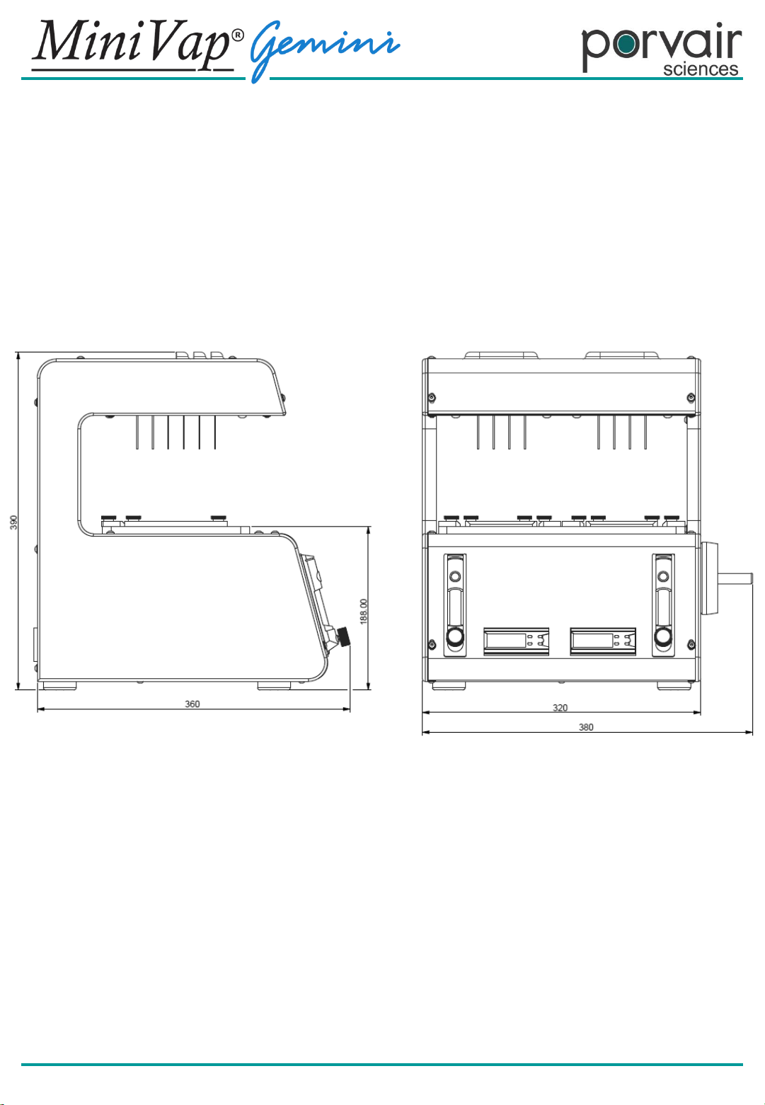
The MiniVap Gemini has been developed as a blow down sample concentrator, to allow
evaporation of solvents, from microplates in minutes, rather than hours. This model is specifically
designed to accommodate two microplates at a time by featuring a double positioned platform.
The instrument eliminates the traditional “bottleneck” of solvent evaporation prior to analysis or
reconstitution in buffer. It has been designed to be used with ANSI/SBS format 96 well plates
(conforming to the standards mentioned on the next page). The instrument when fitted with
compatible straight or spiral needle heads, which offers improved drying efficiency, can be used
with 96 well plates. All evaporator heads are easily interchangeable. The device will
accommodate either 24, 48, or 96 well plates, with straight needles, or spiralled needles (96 plate
only).
The MiniVap Gemini blows heated gas (typically Nitrogen) into the wells and accommodates both
deep and shallow well plates. The platform containing the well plates, is settable in elevation to
suit well plate dimensions and dry-down protocol.
This product has been configured to be simple to install, operate and maintain. Installation
requires connection to a gas supply of nitrogen or clean dry air and a suitable electrical supply.
Safe operation is ensured as the CE marked unit fits into fume cupboards, or may be integrated
into a dedicated fume extraction unit.

Page 5
V 1.1 –August 2017
U s e r I n s t r u c t i o n M a n u a l
Installation
Before use, carry out the following steps:
• Visually inspect MiniVap Gemini for damage.
• Check that correct needle head is supplied and inspect for damage.
• Ensure a suitable power cord is supplied.
• Ensure that gas and electrical supplies are correct – see Specifications & System
Requirements.
• Place MiniVap Gemini on a flat surface with a fume hood or well-ventilated area
• Connect the MiniVap Gemini to gas and electrical supplies – see Connecting the Gas &
Power Supply.
• Fit the Needle Head – see Fitting / Changing Needle Head.
• Carry out adjustments (if needed) of the MiniVap Gemini – see Adjustments.
Report all damaged or missing components to your supplier or distributor immediately.
The MiniVap Gemini can be used with microplates that, as a minimum, conform to the following
standards:
ANSI/SBS 1-2004: Microplates –Footprint dimensions
ANSI/SBS 4-2004: Microplates –Well positions
Microplate Requirements

Page 6
V 1.1 –August 2017
U s e r I n s t r u c t i o n M a n u a l
Risk of Electric Shock
Moving Equipment
WARNING
Refer to accompanying documentation
Earth Protective Conductor
Mains Switch Symbols
DANGER - Hot Surface/Area
Health & Safety
It is Important that the MiniVap Gemini is installed and operated in such a way that all applicable
Heath and Safety requirements are met. It is the users responsibility to ensure that all relevant
Health and Safety Regulations are identified and complied with. Failure to do so, may result in
damage to the equipment and could cause personal injury. In particular, the user should study the
contents of this guide carefully before handling or operating this equipment.
All users should be fully trained and have a full operational knowledge of the equipment.
Under no circumstances will the supplier of this equipment be liable for any incidental, consequential
or any special damages of any kind whatsoever, including but not limited to lost profits arising from,
or in anyway connected with the use of this equipment or this instruction manual.
If the unit is opened or tampered with in any way, the units warranty is invalidated immediately.
WARNING SYMBOLS in accordance with IEC 417
I - 0
I = ON 0 = OFF
!

Page 7
V 1.1 –August 2017
U s e r I n s t r u c t i o n M a n u a l
Health & Safety
Environmental Requirements:
Temperature Range: Operating 15⁰C to 40⁰C Storage 0⁰C to 40⁰C
Relative Humidity: Operating 10% to 80% Storage 10% to 80%
Statement: WARNING - Do not operate this instrument in an atmosphere containing explosive gases.
Statement: WARNING - Only approved, supplied mains cord must be used with this instrument.
Statement: WARNING - If an extension lead is required, the lead MUST be earthed.
Statement: VOLTAGE –The MiniVap Gemini is supplied for direct connection to normal 115VAC
or 230VAC supply, with a variation in supply that gives a voltage range of 108VAC to 250VAC.
•The provided covers MUST be used at ALL times during the operation of the unit.
•At no time should the plates be inserted whilst the unit is in its application state.
•The use of solvents on the unit is not recommended.
•The air supply must be removed and the electrical supply disconnected, prior to the removal of any
covers.
The Mains Plug supplied with the MiniVap Gemini unit, is fitted with the following fuse:
Only refit the correct type of Fuse. Must be IEC127 approved for use in EC Countries.
Must be C.S.A. or UL listed or recognised for use in Canada or the United States of America.
Porvair Sciences Limited accepts no responsibility for the misuse of this equipment.
Supply Fuse fitted in plug Fuse fitted in MiniV
ap
Gemini
230VAC U.K 13 Amp IEC Main inlet to rear of
unit is twin fused, Live &
Neutral fuse. (2 x T10AH
250V)
230VAC Europe No fuse
115VAC No fuse

Page 8
V 1.1 –August 2017
U s e r I n s t r u c t i o n M a n u a l
Power Supply: 115 -240 - V AC 50/60Hz
Fuse Rating: 2 x 10 Amp Anti-surge (T10AH 250V)
Dimensions: 182mm x 442mm x 454mm (W x H x D)
Weight: 19.5Kg
Gas Input: 8mm Inlet
Min Operating Pressure: 4 bar (60 psi)
Max Operating Pressure: 7 bar (100 psi)
Flow: 60 L/min - 200 L/min
Min Operating Temp: 15⁰C
Max Working Temp: 60⁰C
Protection: IP 40
Specifications & System Requirements
Optimum Conditions
Pressure: 5.5 bar (80 psi)
Flow: 140 L/min
Gas Supply Information
A suitable clean, dry, regulated gas supply should be connected to the instrument using 8mm
tubing. Use of a filter / separator in addition to supply regulator is strongly recommended. Typical
gases suitable for use with the MiniVap Gemini are Nitrogen and compressed air.
For samples that are easily oxidised it is strongly recommended that Nitrogen is used. The gas can
be supplied from cylinders/bottles, via in-house systems, local compressor (air) or from a gas
generator (Nitrogen).

Page 9
V 1.1 –August 2017
U s e r I n s t r u c t i o n M a n u a l
What’s in the Box
Before installing your MiniVap Gemini, please check that all the required contents are in the
box. See below for a full list of items.
1 x UK Power Lead 1 x EU Power Lead
1 x US Power Lead
1 x MiniVap Gemini Unit

Page 10
V 1.1 –August 2017
U s e r I n s t r u c t i o n M a n u a l
Product Overview
The MiniVap Gemini can be used in integration with other machinery; please take note of the
dimensions below for accommodating the size of the unit. All dimensions are in mm.

Page 11
V 1.1 –August 2017
U s e r I n s t r u c t i o n M a n u a l
Product Overview
Lifting plate
carrier
(position 1)
Needle head
Lifting plate
carrier
(position 2)
Hand wheel (for
raising & lowering
platform)
System gas
flow control
valve 2
System gas
flow control
valve 1
Gas
temperature
controller 1 Gas
temperature
controller 2

Page 12
V 1.1 –August 2017
U s e r I n s t r u c t i o n M a n u a l
Connecting the Gas & Power Supply
Connecting the Gas Supply
Check that the gas supply is within the system requirements.
The gas supply should be connected to the universal connector female 8mm (internal diameter) on
the rear of the unit. The connecting tube is a one-touch connection.
Gas pressure should not exceed 7 bar (100 PSI). Exceeding this pressure may damage the unit.
Connecting the Power Supply
The MiniVap Gemini uses a standard Euro inlet, which is fused and switched prior to inserting
the connector. Check that the correct voltage is being applied.

Page 13
V 1.1 –August 2017
U s e r I n s t r u c t i o n M a n u a l
BEFORE USING MINIVAP GEMINI CARRY OUT THE FOLLOWING STEPS:
When unpacking your MiniVap Gemini unit, visually inspect the needle array for correct pitch.
•96 well pitch (distance between pins) should be 9.00mm
This maybe checked by offering up a standard 96 well plate.
Check visually, that no obvious damage has occurred during shipping.
Once you have correctly followed the instructions on connecting MiniVap Gemini to gas and
power supplies, the unit is ready for use.
96 Well Head
Fitting / Changing Needle Head

Page 14
V 1.1 –August 2017
U s e r I n s t r u c t i o n M a n u a l
Fitting / Changing Needle Head
Before removing / changing the needle head, disconnect the unit from any electrical
supplies and gas. Also ensure MiniVap Gemini has cooled down sufficiently if used.
•Remove the safety guard.
•To remove the needle head, remove the four fixing screws, using the Allen key provided.
Turning the unit on it’s side may make this process easier (ensure it is placed on a suitable
surface and a cloth is used if necessary for protection).
•Carefully remove the head, avoid bending or damaging needles.
•Inspect gasket for tears and replace if needed.
•When replacing the needle head, great care must be taken to ensure that the gasket is
present and fitted correctly. For ease of fitting; the needle head will fit either way round.
Fixing screw

Page 15
V 1.1 –August 2017
U s e r I n s t r u c t i o n M a n u a l
Disassembled needle head showing 96 spiral needles:
Fitting / Changing Needle Head
Manifold
gasket
Manifold plate /
Needle carrier
Needle Head
Comprising of 24 or 96
spiralled or straight
needles mounted in
the manifold plate /
needle carrier
Please Note: Spare needle heads are available from Porvair
Sciences. In order to fit these to Minivap Gemini, it will be
necessary to first remove the spring clips on the two captive bolts
supplied as part of each head. The bolts will be in an incorrect
position, as supplied, and must first be re-located before the head
can be fitted to Minivap Gemini. A flat-head screwdriver is
supplied with each spare head to assist you to remove the spring
clips.

Page 16
V 1.1 –August 2017
U s e r I n s t r u c t i o n M a n u a l
Operating Instructions
Once the MiniVap Gemini is correctly connected to gas and mains power supplies and a suitable
needle head is installed, as described in the previous sections, the unit is ready to be set up for
use.
This involves the following steps:
•Adjusting the platform
•Platform lifting and lowering
•Temperature setting
•Setting inlet operating pressure
•Setting system gas flow
•Sample concentration using MiniVap Gemini
Turn the power on at the IEC power inlet at the rear of the instrument; the temperature controllers
will display the previously set temperature and ambient temperature of the gas manifold.
Important note: Ensure that the system gas flow control valve is closed otherwise the unit will
start to heat up and dispense gas prematurely.

Page 17
V 1.1 –August 2017
U s e r I n s t r u c t i o n M a n u a l
Adjusting the Platform
The MiniVap Gemini has an adjustable platform, which has adjustment bars that can be moved for
accommodating different samples and optimal positioning.
•Adjustment is carried out by loosening the location thumb screws (done by hand), positioning a
microplate by moving the adjustment bars (sides and rear) and re-tightening the screws.
•Check that the needles are centrally located above each well by raising the platform and
visually aligning the microplate to the needles. This is done by turning the hand wheel anti-
clockwise. If the plate is not located properly, move the carrier to correctly align the plate.
•Raise the platform slowly, checking position of the needles, until they are inserted almost to the
full depth of the wells. Recheck the position periodically during this process and adjust if
necessary. This is particularly important with spiralled needles which could potentially collide
with the side of the wells if inserted beyond the vertical sections of the wells. It may be easier to
loosen all the adjustment bars and gently move the microplate ensuring that it can move freely
without touching the tips of the needles.
Important note: The MiniVap Gemini works by using both positions simultaneously; (gas will run
through both needle heads) therefore if the second plate carrier is not in use ensure that a needle
head is fitted to keep the machine running consistently.
Operating Instructions
Loosen thumb
screws to move
adjustment bars
Rotate anti-
clockwise to lift
plate carrier

Page 18
V 1.1 –August 2017
U s e r I n s t r u c t i o n M a n u a l
Temperature Setting
Operating Instructions
Set / required
temperature
Gas manifold
temperature
For adjusting
temperature and
maintenance functions
For access to
temperature setting
and maintenance
functions
No user functions
Important note: Only press the keys as outlined in these instructions. Pressing key ‘U’ has no effect
during normal operation –no user functions available. Incorrect pressing of either keys ‘P’ or ‘U’ may
result in undocumented / error screens. The display will return to the default screen if no keys
approximately 15 –20 seconds.

Page 19
V 1.1 –August 2017
U s e r I n s t r u c t i o n M a n u a l
Temperature Setting
Once the gas supply is established and the mains power is switched on at the IEC inlet at the
rear of the instrument the temperature controller will display the following screen at start up.
Operating Instructions
After a few seconds the screen will return to its default display: -
Any new unit, may show a negative temperature on power-up (from cold).
This will align itself, once the target temperature has been reached and is perfectly
acceptable.
Gas manifold temperature
Set / required temperature

Page 20
V 1.1 –August 2017
U s e r I n s t r u c t i o n M a n u a l
Temperature Setting
Press key ‘P’, the screen will display:
Adjust temperature setting using keys:
Do not press any keys for approximately 30 seconds . The screen will return to the default
display, shown below:
Important note: The instrument will not start to heat up if the gas flow is less than 25 L/min –
see following sections for setting operating pressure and system gas flow.
Operating Instructions
Table of contents
Other Porvair Sciences Laboratory Equipment manuals
Popular Laboratory Equipment manuals by other brands

Heathrow Scientific
Heathrow Scientific Mini Stirrer 1L instruction manual

Applied Biosystems
Applied Biosystems 7900HT user guide

NEW BRUNSWICK SCIENTIFIC
NEW BRUNSWICK SCIENTIFIC C-24 Guide to operations

Fisherbrand
Fisherbrand HandyStep S operating manual

Beckman Coulter
Beckman Coulter SX4400 Instructions for use

Ametek
Ametek TAYLOR HOBSON FORM TALYSURF i PRO Series Operator's guide