Porvair Sciences MiniVap User manual

In
s
s
tru
c
c
tion Man
u
u
al

2
Issue5–January2014
The information in this user guide, including any apparatus, methods, techniques and
concepts described herein, are the property of Porvair Sciences Limited or its Licensees and
may not be copied, disclosed or used for any purpose not expressly authorised by its owners
thereof.
This document is for information only; the manufacturer accepts no liability for errors
contained herein or for incidental or consequential damages with the furnishing, performance
or use of this material.
Since Porvair Sciences Limited, constantly strives to improve all of its products, we reserve
the right to modify equipment and user guides without prior notice.
No part of this guide may be reproduced in any form or by any means (including storage and
retrieval or translation into a foreign language) without the prior agreement and written
consent of Porvair Sciences Limited.
Copyright © 2003 – 2014 Porvair Sciences Limited
All Rights Reserved
Specifications subject to change without notice. E&OE.

3
Issue5–January2014
Contents
Page
Introduction 4
Installation 5
Microplate Requirements 5
Caution Notes 6
Warning symbols used 7
Environmental requirements 7
System requirements 8
Connecting the MiniVap 9
Fitting / Changing the Needle Head 10
Operating Instructions 12
Operating Instructions – Overview of display screen 13
Operating Instructions – Platform adjustment 13
Operating Instructions – Temperature setting 14
Operating Instructions – AL1 displayed 15
Operating Instructions – Setting Inlet Operating Pressure 16
Operating Instructions – Setting System Gas Flow 16
Sample concentration using MiniVap 17
Recalibrating temperature controller 18
MiniVap over temperature thermal cut-out 22
Specifications 23
Schematic 23
Declaration of Conformity 24
Spare Parts and Accessories 25
Troubleshooting 26
Identifying your MiniVap 26
Maintenance – Cleaning the instrument 27
Maintenance – Cleaning / Examining needles 27
Maintenance – Changing mains protection fuse 29
Warranty and Returns 30

4
Issue5–January2014
Introduction
Porvair Sciences Limited has introduced the compact, stand-alone blow down sample concentrator, to
allow evaporation of solvents from microplates in minutes, rather than hours.
The instrument eliminates the traditional “bottleneck” of solvent evaporation prior to analysis or
reconstitution in buffer. It has been designed to be used with ANSI/SBS format 96 well plates
(conforming to the standards noted below). The instrument when fitted with compatible straight or
spiral needle heads, which offers improved drying efficiency, can be used with 96well plates. It can
optionally be supplied with a 24 well straight needle head to allow evaporation of samples stored in
standard 3.5ml (Ø13.75mm) glass vials when used in conjunction with a suitable carrier plate. A
polypropylene adaptor block designed to hold 48 standard 1.5ml HPLC vials (Chromacol/Agilent type)
is available with a matching 48 well head with straight needles. All evaporator heads are easily
interchangeable.
The samples concentrator blows heated gas (typically Nitrogen) into the wells and will accommodate
both deep and shallow well plates. The location of the needle array is fixed. The platform containing
the well plate can be manually elevated to suit well plate dimensions and to optimise dry-down of
samples.
The concentrator has been configured to be simple to install, operate and maintain. Installation requires
connection to a gas supply and an electrical supply. Safe operation is ensured as the CE marked unit
fits into fume cupboards, or may be integrated into a dedicated fume extraction unit.

5
Issue5–January2014
Installation
Before use, carry out the following steps:
•Visually inspect MiniVap for damage
•Check that correct needle head is supplied and inspect for damage
•Ensure transformer is supplied (if required) and a suitable power cord is available
•Ensure that the hand wheel, used for raising and lowering the platform (plate carrier),
on the right side of the instrument moves freely.
•Ensure that gas and electrical supplies are correct – see System Requirements
•Place MiniVap on a flat surface in a fume hood or well-ventilated area
•Connect the MiniVap to gas and electrical supplies – see Connecting the MiniVap
•Fit the Needle Head – see Fitting / Changing Needle Head
•Carry out adjustment of the MiniVap – see Operating Instructions
Report all damaged or missing components to your supplier or distributor immediately.
Microplate requirements
The MiniVap can be used with 96 well microplates that, as a minimum, conform to the
following standards:
ANSI/SBS 1-2004: Microplates – Footprint dimensions
ANSI/SBS 4-2004: Microplates – Well positions

6
Issue5–January2014
Caution Notes
It is important that the MiniVap is installed and operated in such a way that all applicable Health and
Safety requirements are met. It is the user’s responsibility to ensure that all relevant Health and Safety
Regulations are identified and complied with. Failure to do so may result in damage to the equipment
and could cause personal injury. In particular, the user should study the contents of this guide carefully
before handling or operating this equipment.
Under No circumstances will the supplier of this equipment be liable for any incidental, consequential or
any special damages of any kind whatsoever, including but not limited to lost profits arising from, or in
any way connected with the use of this equipment or this instruction manual.
Warranty is invalidated if the unit is opened or tampered with, in any way, without
prior authorisation of Porvair Sciences or the manufacturer.
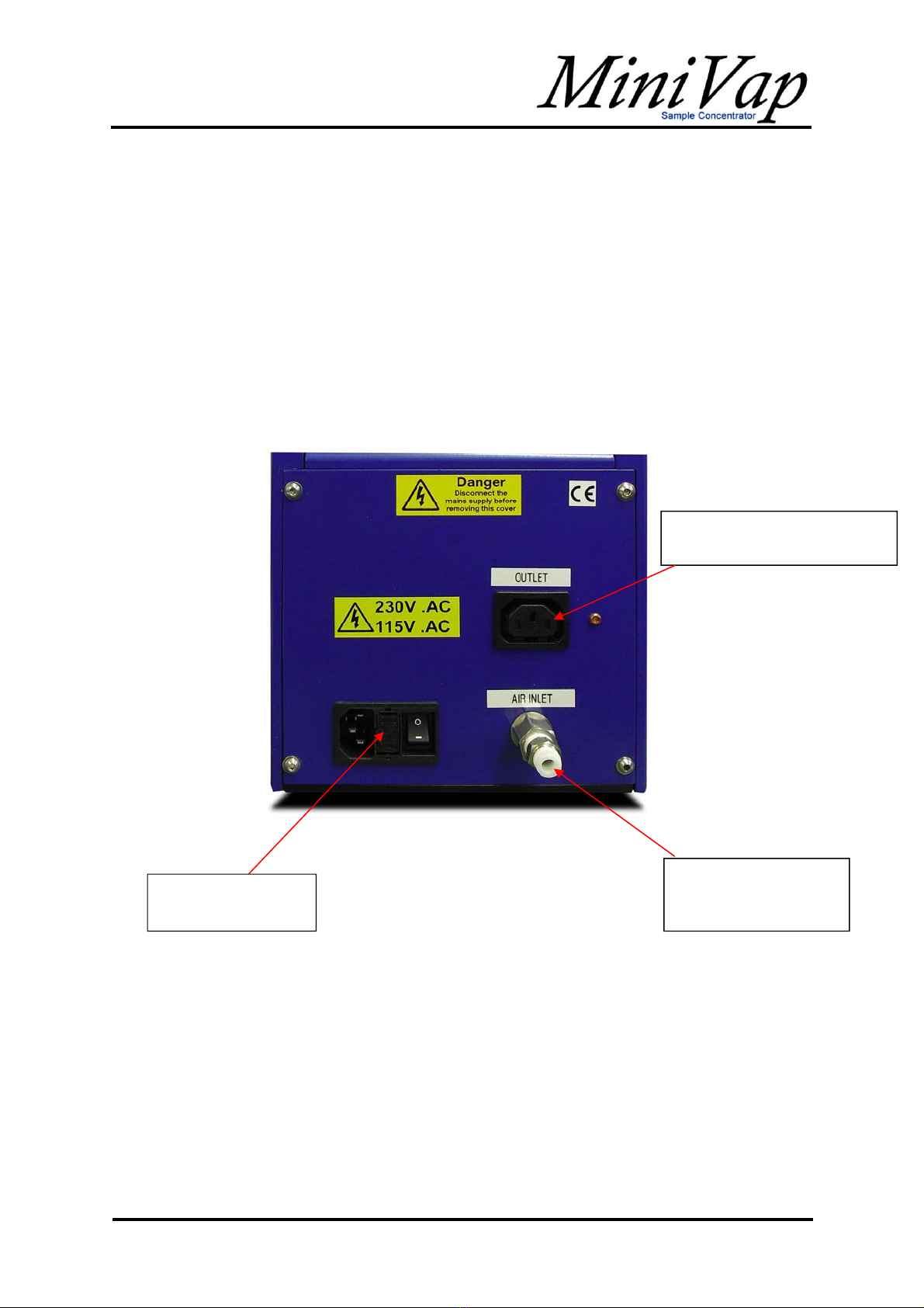
Warning: The MiniVap operates on Dual Voltage mains supply,
either 115V or 230V 50Hz or 60Hz
Warning: Only approved, supplied mains cord set must be used with this instrument.
Refer to System Requirements section for more information.
Warning: If it is required to use an extension lead, the lead must be earthed.
Operational controls
•The height of the platform must be controlled to prevent damage to needles or
microplate
Special requirements
•The instrument is designed to operate at a maximum temperature of 60ºC. Certain
components will become HOT during normal operation of this equipment. Please be
aware of all warning signs relating to hot surfaces
•The instrument must be used in a well-ventilated area. Use of fume extractor or use
in a fume cupboard is recommended.

Issu
War
n
In acco
r
RISK
O
WARNI
Refer t
o
DANG
E
PROT
E
MAINS
I = ON
Envi
T
e5–Januar
y
n
ing S
y
r
dance wit
h
O
F ELECT
R
NG
o
accompa
n
E
R – HOT
S
E
CTIVE CO
N
SWITCH
S
i
ronm
e
T
emperat
u
R
elative H
u
y
2014
y
mbol
s
h
IEC 417
R
IC SHOC
K
n
ying docu
m
S
URFACE
/
N
DUCTOR
S
YMBOLS
O = OFF
e
ntal r
e
u
re range
u
midity (n
o
s
Use
d
K
m
entation
/
HOT ARE
A
TERMINA
L
e
quire
m
o
n-conden
s
d
A
L
m
ents
s
ing)
Operating
Storage
Operating
Storage
I –
O
10ºC –
3
0ºC –
4
10 –
10 –
O
3
0ºC
4
0ºC
8
0%
8
0%
7

8
Issue5–January2014
System Requirements
Gas supply
A suitable clean, dry, regulated gas supply should be connected to the instrument using 6mm
tubing. Use of a filter / separator in addition to supply regulator is strongly recommended.
Typical gases suitable for use with the MiniVap are Nitrogen and compressed air. For
samples that are easily oxidised it is strongly recommended that Nitrogen is used. The gas
can be supplied from cylinders/bottles, via in-house systems, local compressor (air) or from a
gas generator (Nitrogen).
Pressure: 2 bar (30 psi) – 5.3 bar (80 psi)
Flow: 25L/Min – 100 L/min
Optimum conditions: 70 L/min at 5 bar (75 psi)
Warning: Gas pressure must not exceed 5.3 bar (80 psi). Exceeding this pressure may
result in damage to the instrument.
Electrical supply
The MiniVap operates from and electrical supply of 115/240 volts.
The MiniVap utilises a standard fused and switched IEC connector
The MiniVap is supplied with power cords for U.K., U.S.A. and Europe. If the plug fitted is
not suitable for the available supply DO NOT modify it. A suitable power lead should be
available from a reputable local supplier.
The mains inlet on the MiniVap should be fitted with the following fuse:
Supply Fuse fitted in plug Fuse fitted in MiniVap
230VAC U.K
13 Amp IEC Main inlet to rear of
unit is twin fused, Live &
Neutral fuse. (2 x T5AH
250V)
230VAC Europe
No fuse
115VAC
No fuse
Only fit the correct type of fuse.
In Europe, ensure that the fuse is IEC 127 approved.
In Canada and U.S.A ensure that the fuse is CSA or UL listed or recognised for use

9
Issue5–January2014
Connecting the MiniVap
Check gas supply is within system requirements
Connect gas supply using 6mm connector. If a different fitting is required; remove the
existing push-fit adapter using two spanners (one to remove the fitting, the other to constrain
rotation of the bulkhead fitting. Alternative adapters will require a ¼” BSP thread.
MiniVap runs on Dual Voltage main supply 115/230V.
Gas supply inlet (6mm
or ¼” fitting, dependant
on supply)
PowerOutletVoltage,aligned
withInletPowerVoltage
Switched / fused
IEC
power inlet

I
s
Fitti
n
Import
a
Statem
To fit a
N
•
D
•
C
m
N
s
sue5–Jan
u
n
g / C
h
a
nt Note
ent:
N
eedle Hea
d
D
isconnect
f
C
arefully pla
m
anifold – s
e
N
eedle head
Lo
c
po
s
u
ary2014
h
angin
g
The foll
a needl
Conce
n
on Mini
V
It may
b
laid on
i
placed
o
d
to the ins
t
fr
om gas a
n
ce supplie
d
e
e pictures
installed on
c
ation dowel
/
s
ition for he
a
scre
w
Gasket
g
Nee
d
o
wing pictu
e
head to
e
n
trator. Illus
t
V
ap).
b
e easier to
i
ts side. Pl
e
o
n the surf
a
t
rument, ca
r
d electrical
d
gasket ov
e
below:
gas manifol
d
/
alternative
a
d retaining
w
s
located on d
d
le He
a
u
res illustrat
e
ither a Min
t
rations sh
o
carry out t
h
e
ase ensur
e
a
ce to prot
e
r
ry out the
f
supplies, t
o
er
the two l
o
d
d
owels
a
d
e the proc
e
iVap or an
o
w Ultravap
h
e followin
g
e
that a sui
t
e
ct both it a
n
f
ollowing st
e
o
minimise
r
o
cation do
w
Note: B
o
heads m
a
have mo
It is not
n
screws t
h
Dependi
n
manifold
retaining
corners
(
illustrati
o
Normal
Gas m
a
dure used
f
Ultravap S
with splas
h
g
operation
s
t
able soft cl
o
n
d the Ultra
e
ps:
r
isk during
t
w
els on the
u
o
th older instr
u
a
nufactured b
r
e screw hole
s
n
ecessary to fi
h
an noted in t
h
n
g on the des
i
it may be ne
c
screws in dia
g
alternative po
n)
position for
h
a
nifold
f
or fitting
ample
h
guard ins
t
s
with the U
oth or tissu
a
vap if this i
s
t
he next st
e
underside
o
uments and n
b
efore mid-20
0
s
than illustra
t
i
t more retaini
n
h
e instruction
s
i
gn of the hea
c
essary to ins
e
gonally oppo
s
o
sition noted i
n
h
ead retaini
n
Spla
s
alled. (Not
u
l
t
ravap
e
is
s
done.
e
ps
o
f the gas
eedle
0
9 may
t
ed.
n
g
s
.
d
/ gas
e
rt the
s
ite
n
n
g screws
h guard
10
u
sed

Issue5–
A
l
h
e
January201
•
C
s
p
•
T
•
R
To rem
o
followin
g
•
A
•
D
•
U
N
•
C
•
•
F
ternative po
s
e
ad retainin
g
Issue5–J
a
4
C
arefully pl
s
ocket hea
d
p
laced in t
h
T
ighten so
c
R
econnect
o
ve a need
l
g steps:
A
llow instr
u
D
isconnect
U
sing Allen
N
eedle He
a
C
arefully r
e
Inspect ga
s
Fit new / cl
e
s
ition for
g
screws
a
nuary2014
ace Needl
e
d
screws a
n
h
e centre h
o
c
ket screws
gas and el
e
l
e head, ty
p
u
ment to co
o
from gas a
key (Hex
w
a
d. Retain
t
e
move the
h
s
ket for tear
e
aned hea
d
MiniVa
p
e
Head on t
o
n
d Allen ke
y
o
les at the f
r
securely
e
ctrical sup
p
p
ically for cl
e
o
l, if it has
b
nd electric
a
w
rench) su
p
t
he screws
h
ead – avoi
d
s
and repla
d
as instruc
t
p
illustrating
o
o
p of the g
a
y
(Hex wre
n
r
ont and b
a
p
lies
e
aning, rep
a
b
een in use
a
l supplies,
p
plied; rem
o
for re-fittin
g
d
bending
o
ce if requir
e
t
ed above
o
ptional 24
w
gas man
i
a
sket and fi
x
n
ch) provid
e
a
ck of the n
e
a
ir or repla
c
to minimis
e
o
ve the soc
k
g
the head.
o
r damagin
g
e
d
w
ell Needle
H
i
fold.
x
it in positi
o
e
d. The scr
e
edle head.
c
ement, ca
r
e
risk durin
g
k
et screws
r
g
needles
H
ead installe
d
o
n using th
e
r
ews shoul
d
.
r
ry out the
g
the next s
t
retaining th
d
on
e
d
be
t
eps
e
11

12
Issue5–January2014
Operating Instructions
Once the MiniVap is correctly connected to gas and mains power supplies and a suitable
Needle Head is installed, as described in the previous sections, the unit is ready to be set
up for use.
This involves the following steps:
•Platform adjustment
•Temperature setting
•Setting Inlet Operating Pressure
•Setting System Gas Flow
•Sample concentration using MiniVap
Turn the power on at the IEC power inlet at the rear of the instrument; the temperature
controller will display the previously set temperature and ambient temperature of the gas
manifold.
Important note: Ensure that the system gas flow control valve is closed otherwise the
unit will start to heat up and dispense gas prematurely
Moving platform
Needle head
Hand wheel for
raising and lowering
platform
Gas temperature
controller
System gas
flow control
valve

Issue5–Ja
n
Overvie
w
Important
Platform
a
Gas m
a
Set / r
e
Moving pl
n
uary2014
w
of displa
y
note:
a
djustmen
t
a
nifold temp
e
e
quired temp
atform
Side a
d
y
screen
Only pres
s
Pressing
k
functions
a
result in u
n
screen if n
t
e
rature
erature
d
justment ba
r
s
the keys a
ey ‘U’ has
n
a
vailable. I
n
n
document
e
o
keys app
r
r
s
a
s outlined i
n
o effect d
u
n
correct pr
e
e
d / error s
c
r
oximately
1
n
these ins
t
u
ring norm
a
e
ssing of ei
t
c
reens. Th
e
1
5 – 20 se
c
t
ructions.
a
l operation
her keys ‘
P
e
display wi
l
c
onds.
N
t
– no user
P
’ or ‘U’ ma
y
ll return to
t
N
o user funct
For ad
j
tempera
maintenan
c
For ac
c
temperature
maintenan
c
Hand w
h
and lo
w
Rear ad
y
t
he default
ions
j
usting
ture and
c
e functions
c
ess to
setting and
c
e functions
h
eel for raisi
n
w
ering platfor
j
ustment ba
r
13
n
g
m
r

Issue5–
J
To avoi
d
used s
h
MiniVa
p
To corr
e
•
L
c
•
P
•
R
•
V
•
S
a
•
R
•
R
a
p
w
s
m
n
•
L
Tempe
r
Once t
h
rear of
t
After a
f
A
ny ne
w
This wil
TLK32
J
anuary201
4
d
damage
t
h
ould be se
t
p
is fitted wi
e
ctly positi
o
L
oosen bot
c
ounter-clo
c
P
lace Micr
o
R
aise platf
o
V
isually ali
g
S
ecure in
p
a
nd tighten
R
echeck p
o
R
aise the
p
a
lmost to t
h
p
rocess an
d
w
hich coul
d
s
ections of
m
ove the
m
n
eedles. S
L
ower the
p
r
ature sett
i
h
e gas sup
p
t
he instrum
e
f
ew second
w
unit (132
3
l align itsel
f
4
t
o either Ne
t
on the mo
v
th adjustab
o
n the micr
o
h rear and
s
c
kwise.
o
plate on m
o
rm using h
g
n plate so
p
osition by
m
ing the knu
o
sition and
a
p
latform slo
w
h
e full dept
h
d
adjust if
n
d
potentiall
y
the wells.
I
m
icroplate e
n
ecure in p
o
p
latform to i
t
i
ng
p
ly is establ
i
e
nt the tem
s the scree
3
3 On), ma
y
f
, once the
t
edle Head
o
v
ing platfor
m
le bars mo
u
o
plate, carr
y
s
ide adjust
m
o
ving platf
o
and wheel
t
hat the ne
e
m
oving loc
a
r
led retaini
n
a
djust if re
q
w
ly, checki
n
h
of the well
s
n
ecessary.
y
collide wit
h
I
t may be e
a
n
suring tha
t
sition once
t
s home po
i
shed and t
h
p
erature c
o
n will retur
n
y
show a n
e
t
arget temp
o
r sample
p
m before s
e
u
nted on th
e
y
out the fol
m
ent bars
b
o
rm inside
a
until needl
e
e
dles are p
o
a
tion bars u
n
n
g by rotati
n
q
uired
n
g position
o
s. Rechec
k
This is par
t
h
the side
o
a
sier to loo
s
t
it can mo
v
this check
sition usin
g
h
e mains p
o
o
ntroller will
n
to its defa
u
e
gative te
m
erature ha
s
K32
Set / requi
r
Gas m
a
p
lates, the
p
e
tting the in
e
moving p
l
l
owing step
b
y rotating
k
a
djustment
b
e
s are just
a
o
sitioned c
e
n
til they ar
e
n
g clockwis
e
o
f the need
k
the positi
o
icularly im
p
f the wells i
s
en all the
a
v
e freely wit
is carried o
g
the hand
w
o
wer is swi
t
display the
u
lt display:
-
m
perature o
n
s
been rea
c
r
ed tempera
t
a
nifold temp
p
osition of t
h
s
trument.
T
atform – a
s
s
:
k
nurled reta
i
b
ars
a
bove the t
o
e
ntrally abo
v
just touchi
n
e
l
es, until th
e
o
n periodic
a
ortant with
f
inserted b
a
djustment
hout touchi
u
t
w
heel.
t
ched on at
following s
-
n
powe
r
-up
hed and is
t
ure
erature
h
e micropl
a
T
o allow thi
s
s
illustrated
ining scre
w
o
p of the pl
a
v
e each w
e
ng the mic
r
e
y are inse
r
a
lly during t
h
spiralled n
e
b
eyond the
v
bars and g
e
ng the tips
the IEC inl
e
s
creen at st
a
(from cold
)
perfectly o
k
a
te to be
s
, the
above.
w
s
a
te
e
ll
oplate
r
ted
h
is
e
edles
v
ertical
e
ntly
o
f the
e
t at the
a
rt up.
)
.
k
ay.
14

Issue5–
J
Press k
Adjust t
Do not
p
The sc
r
Importan
This inf
o
AL1 di
s
If key ‘
P
the foll
o
with th
e
Do not
p
The sc
r
J
anuary201
4
ey ‘P’, the
s
emperatur
e
p
ress any
k
r
een will ret
u
tnote:
o
rmation on
ly
s
played (T
L
P
’ is incorre
o
wing scree
e
MiniVap.
p
ress any
k
r
een will ret
u
4
s
creen will
d
e
setting usi
k
eys for ap
p
u
rn to the d
The inst
r
the gas
f
following
pressur
e
ly
applies to
L
K32)
ctly presse
d
n will be di
s
k
eys for ap
p
u
rn to the d
d
isplay
ng ke
p
roximately
efault displ
a
r
ument will
n
low is less
t
sections f
o
and syste
m
TLK32 Disp
l
d
after setti
n
s
played. T
h
p
roximately
efault displ
a
ys
30 second
s
a
y, shown
b
n
ot start to
t
han 25 L/
m
or
setting o
p
m
gas flow.
l
a
y
n
g the tem
p
h
is function
30 second
s
a
y, shown
b
s
b
elow:
heat up if
m
in – see
p
erating
p
erature,
is not use
d
s
b
elow:
Note: Fo
r
and TLK-
3
will show
a
ambient g
Typic
a
To set te
m
P
P
P
T
d
t
e
To set te
m
P
P
W
T
d
t
e
r older instru
m
3
1 controllers
a single line
d
g
as manifold t
e
a
l single line
d
m
perature usi
n
P
ress ‘P’ key
P
ress k
e
P
ress ‘P’ key
t
T
he display wi
d
efault screen
emperature o
f
m
perature usi
n
P
ress ‘P’ key
P
ress k
e
W
ait15-20 se
c
T
he display wi
d
efault screen
emperature o
f
m
ents with TL
K
the default s
c
isplay indicati
e
mperature:
d
isplay (TLK-
3
n
g TLK-38;
e
ys to adjust
v
t
o save value
ll return to th
e
indicating cu
r
f
the gas man
n
g TLK-31;
e
ys to adjust
v
c
onds
ll return to th
e
indicating cu
r
f
the gas man
15
K
-38
c
reen
ng the
3
8)
v
alue
e
r
rent
ifold
v
alue
e
r
rent
ifold

Issue5–
J
Sett
i
To obtai
n
adjustin
g
Note:
To set
u
•
E
•
A
T
o
o
•
T
o
Warnin
Setting
The Mi
n
perfor
m
gas flo
w
Once t
h
maxim
u
valve t
o
clockwi
s
Once t
h
to heat
will star
t
The dia
high ga
s
sample
without
J
anuary201
4
i
ng Inl
e
n
optimum
p
g
the Syste
m
u
p the Inlet
E
nsure Sy
s
A
djust sup
p
T
he instru
m
o
ptimum p
e
o
f 5 bar (7
5
T
he gas su
o
ptimum p
r
g:
System G
n
iVap is de
s
m
ance a set
t
w
meter.
h
e system i
n
u
m that can
o
give the d
e
s
e.
h
e flow rate
the gas an
d
t
to rise.
meter of th
e
s
flow rate
s
disturbanc
e
the risk of
c
Decrea
s
Increa
s
4
e
t Ope
r
p
erformanc
e
m
Gas Flo
w
This se
t
shown
o
Due to
i
pressu
r
Operating
P
s
tem Gas F
l
p
ly system
r
m
ent will op
e
e
rformance
5
psi)
pply syste
m
r
essure of
5
Gas pr
e
pressu
r
as Flow
s
igned to w
o
t
ing of 70 L
/
n
let pressu
r
be maintai
n
e
sired flow
r
exceeds 2
5
d
the temp
e
e
needles
h
s
(> 75 L/mi
n
e
. This all
o
c
ross conta
s
egasflow
s
egasflow
r
ating
e
it is nece
s
w
– see follo
t
ting is carr
i
o
n the syst
e
i
nternal pre
r
e through i
n
P
ressure, c
a
l
ow Meter
v
r
egulator to
e
rate with o
it is recom
m
m
should be
bar (75 ps
i
e
ssure mus
t
r
e may resu
o
rk with a g
/
min is reco
r
e is set to
5
n
ed, adjust
r
ate by turn
5
L/min the
er
ature indi
c
h
as been o
p
n
) to be us
e
ws quicker
mination.
S
y
Press
u
s
sary to co
r
o
wing secti
o
i
ed out at t
h
e
m gas flo
w
ssure and
d
n
dividual n
e
a
rry out th
e
v
alve is full
y
a value of
b
o
pe
r
ating pr
e
m
ended th
a
set to the
m
i
) cannot b
e
t
not excee
d
u
lt in damag
g
as flow bet
w
o
mmended.
5
bar (75 p
s
the syste
m
n
ing the val
v
instrument
c
ated on th
e
p
timised to
a
e
d while mi
n
sample co
n
y
stem gas fl
o
u
re
r
rectly set t
h
o
n.
h
e supply r
e
w
meter.
d
istribution
e
edles.
e
following
s
y
closed (tu
r
b
etween 3
b
e
ssures as
a
t the regul
a
m
aximum s
e
achieved
o
d
5.3 bar (
8
e to the ins
w
een 25 a
n
This is the
s
i), or the
gas flow
v
e counter-
will start
e
display
a
llow
n
imising
n
centration
o
w valve
h
e gas sup
p
e
gulator an
d
l
osses this
i
tep:
r
n clockwis
e
b
ar (45 psi)
low as 2 b
a
a
to
r
is set t
o
u
stainable
p
or
maintain
e
8
0 psi). Ex
c
tr
ument.
n
d 100 L/mi
n
value sho
w
p
ly to the in
s
d
is not the
v
is not the g
a
e
)
and 5 bar
(
a
r (30 psi)
b
o
supply a
p
p
ressure if
t
e
d.
c
eeding thi
s
n. For opti
m
w
n on the s
y
s
trument b
e
v
alue
a
s
(
75psi).
b
ut for
p
ressure
t
he
s
m
um
y
stem
16
e
fore

17
Issue5–January2014
Sample Concentration using MiniVap
To proceed with sample concentration using the MiniVap carry out the following steps:
•Set temperature and gas flow as described in previous sections
•Wait for instrument to reach the set temperature
•Place the microplate containing samples in correct position on platform
•Raise the moving platform by turning the hand wheel, located on right side of the
instrument, counter-clockwise until the needles are approximately 4mm from the top
of the plate or the sample.
•Allow the MiniVap to concentrate the sample adjusting the position of the moving
platform periodically, if required.
•On completion; lower moving platform to its home position by turning the hand wheel
clockwise.
•Remove microplate with concentrated sample.

18
Issue5–January2014
Recalibrating Temperature Controller
Even though the temperature settings have been set under controlled laboratory conditions,
it is recognised that they may need to be adjusted to compensate for local environmental
conditions. By carrying out the following procedure the operator may introduce an „offset‟
temperature adjustment to suit actual conditions.
Important Note: The following procedure must be carried out by a suitably qualified
technician. Failure to follow these instructions exactly, or the
adjustment of other undocumented parameters, could render the
instrument inoperable resulting in the instrument being returned to the
manufacturer for repair and re-calibration.
Important Note: Please consult your suppliers or Porvair Sciences directly if you
require to carry out recalibration of older TLK-38 or TLK-31
temperature controllers.
For example: If the temperature displayed is 60°C and the temperature measured from the needles is
55°C then an offset of „5‟will typically be required.
After adjustment the temperatures must be allowed to stabilise for a few minutes before checking. All
gas temperature measurements should be carried out using a suitable calibrated thermo-probe. For
further information, please contact your supplier or Porvair Sciences direct.
K32
Press and hold ‘P’ for 3 seconds.
Hold ‘Up’ Arrow until 1400 is reached.
Press ‘P’
Press ‘U’ eleven times until ‘cAL’ is displayed.

19
Issue5–January2014
Press ‘P’ twice to enter Calibration Mode and display ‘ALo’
You can now edit the calibration setting. This should be carried out at 40 L/min
Once settings are changed, press ‘P’ once, then ‘U’ once.
This will show ‘cAL’. Now turn the unit off and re-power.
If re-adjustment is required, repeat the steps above.

Issue5–
J
TLK
3
From t
h
Press
a
Press k
Using th
e
of the b
u
the valu
e
Press k
Press t
h
J
anuary201
4
3
2
h
e default d
i
a
nd hold ke
y
ey ‘P’, the
s
e
butto
n
u
tton. Keep
e
is oversh
o
ey ‘P’, the
s
h
e butto
n
4
i
splay, sho
w
y
‘P’, the s
c
s
creen will
d
n
, scroll the
the button
o
t use the
s
creen will
d
n
once. Th
e
w
n below:
c
reen will di
s
d
isplay:
display to
s
depressed
button u
d
isplay:
e
screen di
s
s
play:
s
how ‘381’.
to scroll r
a
ntil the scr
e
s
plays:
The valu
e
a
pidly throu
g
e
en display
s
will increa
s
g
h the avai
s
:
s
e for each
i
lable settin
press
gs. If
20
Table of contents
Other Porvair Sciences Laboratory Equipment manuals
Popular Laboratory Equipment manuals by other brands

Witeg
Witeg Wisd WiseTherm WHM operating manual

Thermo Scientific
Thermo Scientific SpeedVac SRF110 Installation and operation manual

Ivoclar Vivadent
Ivoclar Vivadent PrograPrint Clean Short instructions

SciCan
SciCan statim 2000 G4 Operator's manual

PASCO
PASCO SE-3607 Product guide

BIO RAD
BIO RAD Mini-PROTEAN II Assembly guide