Posital Fraba IXARC OCD-EEC1B-1213-C12V-PRM User manual

Version 2020-12-02 Page 1 UME-xCx-EEC1
ABSOLUTE IXARC ROTARY ENCODER WITH ETHERNET/IP INTERFACE
USER MANUAL
IXARC ABSOLUTE ROTARY ENCODER WITH ETHERNET/IP INTERFACE
USER MANUAL
IXARC ABSOLUTE ROTARY ENCODER WITH ETHERNET/IP INTERFACE
USER MANUAL
IXARC ABSOLUTE ROTARY ENCODER WITH ETHERNET/IP INTERFACE
USER MANUAL
IXARC ABSOLUTE ROTARY ENCODER WITH ETHERNET/IP INTERFACE

Version 2020-12-02 Page 2 UME-xCx-EEC1
ABSOLUTE IXARC ROTARY ENCODER WITH ETHERNET/IP INTERFACE
USER MANUAL
Imprint
POSITAL GmbH
Zeppelinstraße 2,
D-50667 Köln
Telefon +49 (0) 221 96213-0
Fax +49 (0) 221 96213-20
Internet http://www.posital.com
E-Mail info@posital.eu
Copyright
The company POSITAL GmbH claims copyright
on this documentation. It is not allowed to modi-
fy, extend, copy, or hand over to a third party
this documentation without written approval by
the company POSITAL GmbH. Nor is any liabil-
ity assumed for damages resulting from the use
of the information contained herein. Further, this
publication and features described herein are
subject to change without notice.
Alteration of Specifications reserved
Technical specifications, which are described in
this manual, are subject to change due to our
permanent strive to improve our products.
Disclaimer of Warranty
POSITAL GmbH makes no representations or
warranties, either express or implied, by or with
respect to anything in this manual. Furthermore,
POSITAL shall not be liable for any implied war-
ranties of merchantability and fitness for a par-
ticular purpose or for any indirect, special, or
consequential damages.
Document information
File name: UME-xCx-EEC
Date: Version 2020-12-02
Version number: 1.2
Author: HBA
Phone Service
For technical support, questions, and sugges-
tions for improving our products and documenta-
tions call our telephone line +49 (0) 221-96213-
0.

Version 2020-12-02 Page 3 UME-xCx-EEC1
ABSOLUTE IXARC ROTARY ENCODER WITH ETHERNET/IP INTERFACE
USER MANUAL
IXARC Absolute ROTARY ENCODER WITH
ETHERNET/IP Interface________________1
1. Introduction________________________ 5
1.1 Control and Information Protocol (CIP)____ 5
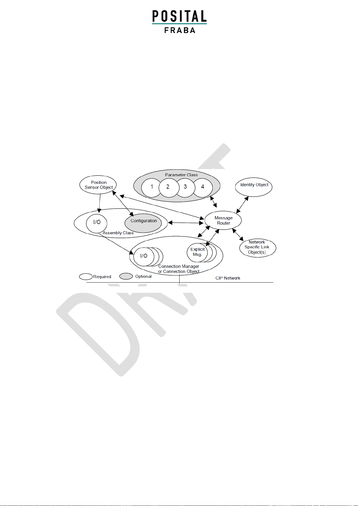
1.2 Object model ________________________ 6
2. Data Transmission ___________________ 6
2.1 Implicit Messaging I/O Connection_____ 7
2.1.1 I/O Assembly Instances_______________ 8
2.1.1.1 Data Attribute Format ______________ 8
2.1.2 Data Mapping ______________________ 9
2.1.3 Data Mapping (Parameter) ___________ 10
2.1.3.1 Data Offset ______________________ 10
2.1.4 Connection Path ___________________ 11
2.2 Explicit Messaging _________________ 12
2.2.1 CIP Common Services for Position Sensor
Objects (Class 0x23hex) __________________ 12
2.2.2 Position Sensor Objects _____________ 13
2.3 TCP/IP Interface Object_____________ 14
2.3.1 Status Instance Attribute (01hex)_______ 15
2.3.2 Configuration Instance Attribute (02hex) 16
2.3.3 Configuration Control Inst. Attribute (04hex)
_____________________________________ 16
2.3.4 Physical Link Object (05hex) ___________ 17
2.3.5 Interface Configuration (06hex) ________ 17
2.3.6 Host Name________________________ 17
2.4 Ethernet Link Object _______________ 18
2.4.0 Instance Attributes _________________ 19
Control Bits ____________________________ 22
Example ______________________________ 22
Use on Transmit data size double (4 bytes)
00000064 for Auto-negotiation = disable on 100
MBaud _______________________________ 22
2.4.1 Interface Flags _____________________ 23
2.4.2 Common Services __________________ 23
2.4.3 Link Object Instances _______________ 24
2.5 Setting parameters with scanners ____ 24
2.5.1 Read out position value _____________ 25
2.5.2 Set preset value____________________ 25
2.5.3 Get preset value ___________________ 26
3 Diagnostics________________________ 27
4 Programmable Parameters___________ 29
4.1 Direction Counting ___________________ 29
4.2 Scaling Function Control_______________ 29
4.3 Resolution per Revolution _____________ 29
4.4 Total Resolution _____________________ 30
4.5 Preset Value ________________________ 30
4.6 Velocity Format _____________________ 31
4.7 Velocity Filter _______________________ 31
4.8 Endless Shaft________________________ 31
4.9 Parameter Control Priority _____________ 32
4.10 Available Alarms and Warnings ________ 32
4.11 Device Level Ring ___________________ 33
5. Installation _______________________ 34
5.1 Electrical connection _________________ 34
5.2 Ethernet cables ______________________ 34
6 Power On_________________________ 35
7 Installation________________________ 35
7.1 Rockwell configuration tools ________ 35
7.1.1 Setting IP-Address (BOOTP/DHCP) _____ 35
7.1.2 Configuration RSLinx Classic™_________ 38
7.1.3 RSNetWorx™ ______________________ 40
7.1.4 Configuration RSLogix 5000 __________ 43
7.2 VLAN Configuration over a Layer 3 Switch
__________________________________ 51
8 FAQ _____________________________ 52
9 Glossary __________________________ 53
10 Revision index ____________________ 55

Version 2020-12-02 Page 4 UME-xCx-EEC1
ABSOLUTE IXARC ROTARY ENCODER WITH ETHERNET/IP INTERFACE
USER MANUAL
List of Tables
Table 1: Communication Messages 7
Table 2: I/O Assembly Instances 8
Table 3: Data Attribute Format 9
Table 4: Data Mapping 9
Table 5: Assembly Instance Configuration: 7, size 14
Bytes 10
Table 6: Data Offset 10
Table 7: Connection Path 11
Table 8: CIP Position Sensor Objects –Save / Restore
12
Table 9: CIP Position Sensor Objects –Instance
Attributes 13
Table 10: TCP/IP Interface Objects Overview 14
Table 11: TCP/IP Interface Objects –Attribute 01hex
15
Table 12: TCP/IP Interface Objects –Attribute 02hex
16
Table 13: TCP/IP Interface Objects –Attribute 04hex
16
Table 14: TCP/IP Interface Objects –Attribute 05hex
17
Table 15: TCP/IP Interface Objects –Attribute 06hex
17
Table 16: TCP/IP Interface Objects –Host Name 17
Table 17: Ethernet Link Objects Overview 18
Table 18: Ethernet Link Objects –Instance Attributes
19
Table 19: Ethernet Link Objects –Control Bits 22
Table 20: Ethernet Link Objects –Interface Flags 23
Table 21: Ethernet Link Objects –Common Services
23
Table 22: Link Object Instances 24
Table 23: Module Status Indicator Stat1/Stat2 27
Table 24: Network Status Indicator Stat2 28
Table 25: Direction Counting 29
Table 26: Direction Counting Bits 29
Table 27: Scaling Function Control 29
Table 28: Scaling Function Control Bits 29
Table 29: Resolution per Revolution 29
Table 30: Total Resolution 30
Table 31: Preset Value 30
Table 32: Velocity Format 31
Table 33: Velocity Filter 31
Table 34: Endless Shaft 32
Table 35: Reserved Error! Bookmark not defined.
Table 36: Parameter Control Priority 32
Table 37: Alarms 33
Table 38: Warnings 33
Table 39: Data Pin Assignment 34
Table 40: Power Supply Pin Assignment 34
Table 41: Ethernet cable RJ45-M12 crossed 34
Table 42: Ethernet cable RJ45-M12 straight 34
Table 43: Ethernet cable M12-M12 crossed 34
Table 44: Rotary Switches Allowed IP Addresses 37
Table 45: Example of VLAN IP Addresses Allocation
51
Table 46: Glossary 55
Table 47: Revision Index 55
List of Figures
Figure 1: Setup of an Ethernet Data Package on Layer
2................................................................................. 5
Figure 2: CIP OSI Layers........................................... 5
Figure 3: Ethernet/IP Object Model............................ 6
Figure 4: Data Transmission in Ethernet/IP................ 6
Figure 5: Generic Module Communication Parameters
................................................................................... 7
Figure 6: Diagnostic LEDs.........................................27
Figure 7: Endless Shaft.............................................32
Figure 8: Device level Ring .......................................33
Figure 9: Ethernet Connector....................................34
Figure 10: Power Supply Connector .........................34
Figure 11: IP Address Rotary Switches.....................37
Figure 12: VLAN Setup .............................................51

Version 2020-12-02 Page 5 UME-xCx-EEC1
ABSOLUTE IXARC ROTARY ENCODER WITH ETHERNET/IP INTERFACE
USER MANUAL
1. Introduction
Absolute rotary encoders provide a definite value
for every possible position. All these values are
reflected on either code discs, either Hall-effect
sensors, depending on the used technology. In the
case of an optical encoder, the beams of infrared
LEDs are sent through code discs and detected by
Opto-Arrays. For a magnetic one, a rotating mag-
net attached to the shaft creates a field whose
direction is measured by the Hall-effect sensor.
The output signals are electronically amplified, and
the resulting value is transferred to the interface.
The absolute rotary encoder has a maximum reso-
lution of 65,536 steps per revolution (16 bits). The
multiturn version can detect up to 16,384 revolu-
tions (14 bits). Therefore, the largest resulting
resolution is 30 bits = 1,073,741,824 steps. The
standard singleturn version is 13 bits, the standard
multiturn version 25 bits.
The integrated Ethernet interface of the absolute
rotary encoder supports all necessary EtherNet/IP
functions.
The protocol supports the programming of the
following additional functions in several ways:
1. Code sequence (complement)
2. Resolution per revolution
3. Total resolution
4. Preset value
5. IP-Address
6. DLR
The functioning of the absolute rotary encoders
under general aspects of the EtherNet/IP interface
is guaranteed. The data will be transmitted in a
standard Ethernet frame in the data section (see at
the bottom of this side the pink field with the blue
frame).
The MAC address of each encoder is available on
the type label.
The IP address can be programmed with DHCP or
BOOTP via the configuration tools of the PLC.
The physical interface support auto negotiation
and auto crossing.
General information’s about EtherNet/IP are avail-
able at:
www.ethernetip.de (German)
https://www.odva.org/technology-standards/key-
technologies/ethernet-ip/ (English)
EtherNet/IP data
Figure 1: Setup of an Ethernet Data Package on Layer 2

Version 2020-12-02 Page 5 UME-xCx-EEC1
ABSOLUTE IXARC ROTARY ENCODER WITH ETHERNET/IP INTERFACE
USER MANUAL
1.1 Control and Information Protocol (CIP)
The EtherNet/IP specification defines the Applica-
tion Layer and the Physical Layer. The Data Link
layer is based on the CAN-specification. For the
optimal industrial control will be defined two different
messaging types. I/O messaging (Implicit Messag-
ing) and explicit messaging. With Implicit Messag-
ing, I/O data are exchanged in real time whereas
Explicit Messaging is mostly used for device config-
uration.
CIP (Common Industrial Protocol) make for the user
available four essential functions:
•Unique control service
•Unique communication service
•Unique allocation of messaging
•Common knowledge base
Figure 2: CIP OSI Layers

Version 2020-12-02 Page 6 UME-xCx-EEC1
ABSOLUTE IXARC ROTARY ENCODER WITH ETHERNET/IP INTERFACE
USER MANUAL
1.2 Object model
EtherNet/IP describes all data and functions of a
device considering an object model. By means
of that object-oriented description, a device can
be completely defined with single objects. An
object is defined across the centralization by
associated attributes (e.g. process data), its
functions (read or write access of a single attrib-
ute) as well as by its defined behaviors. The
absolute rotary encoder supports the Encoder
Device Type: 22hex. This is programmable, see
chapter 4.1. All parameters will be used with Big
Endian notation.
Figure 3: Ethernet/IP Object Model

Version 2020-12-02 Page 6 UME-xCx-EEC1
ABSOLUTE IXARC ROTARY ENCODER WITH ETHERNET/IP INTERFACE
USER MANUAL
2. Data Transmission
The data transmission within the EtherNet/IP net-
work is realized by implicit or explicit messaging.
Explicit messages are split in unconnected and
connection-based versions. Unconnected mes-
sages will be used by EtherNet/IP scanners.
Figure 4: Data Transmission in Ethernet/IP

Version 2020-12-02 Page 7 UME-xCx-EEC1
ABSOLUTE IXARC ROTARY ENCODER WITH ETHERNET/IP INTERFACE
USER MANUAL
Input Only
It is possible to open 5 implicit and 15 explicit connections with the encoder. Input Only connections can
only work if all of the parameters are set in the PLC accordingly to the encoder parameters.
Assembly
Config
Output Instance
Input Instance
Connection Manager
Config
Connection Point 1
Connection Point 2
Input Only
0x7Ahex (122)
0x69hex (105)
0x01 Position value
0x03 Position value + velocity
Table 1: Communication Messages
Figure 5: Generic Module Communication Parameters

Version 2020-12-02 Page 8 UME-xCx-EEC1
ABSOLUTE IXARC ROTARY ENCODER WITH ETHERNET/IP INTERFACE
USER MANUAL
2.1 Implicit Messaging I/O Connection
Provide dedicated, special-purpose communica-
tion paths between a producing application and
one or more consuming applications for the
purpose of moving application-specific data. This
is often referred to as implicit messaging. Class
0 and 1 are supported.
2.1.1 I/O Assembly Instances
Instance
Type
Name
1
Input
Position Value 32 bits unscaled
2
Input
Position Value 32 bits scaled and Warning Flag 8 bits
3
Input
Position Value 32 bits and Velocity 32 bits
120
Input
Position Value 32 bits, Velocity Value 32 bits, Acceleration Value 32 bits and
Warning Flag 8 bits
121
Input
Position Value 32 bits, Velocity Value 32 bits, Acceleration Value 32 bits, Tem-
perature Value 32 bits and Warning Flag 8 bits
122
Output
Direction Counting Toggle 8 bits, Scaling Function Control 8 bits, Measuring Units
per Revolution 32 bits, Total Measuring Range 32 bits, Velocity Format 16 bits,
Velocity Filter 8 bits, Parameter Control Priority 8 bits
Table 2: I/O Assembly Instances
2.1.1.1 Data Attribute Format
Instance
Byte
Bit 7
Bit 6
Bit 5
Bit 4
Bit 3
Bit 2
Bit 1
Bit 0
1
0
Position Value (low Byte)
1
2
3
Position Value (high Byte)
2
0
Position Value (low Byte)
1
2
3
Position Value (high Byte)
4
Warning
Alarm
3
0
Position Value (low Byte)
1
2
3
Position Value (high Byte)
4
Velocity Value (low Byte)
5
6
7
Velocity Value (high Byte)

Version 2020-12-02 Page 9 UME-xCx-EEC1
ABSOLUTE IXARC ROTARY ENCODER WITH ETHERNET/IP INTERFACE
USER MANUAL
Instance
Byte
Bit 7
Bit 6
Bit 5
Bit 4
Bit 3
Bit 2
Bit 1
Bit 0
120
0
Position Value (low Byte)
1
2
3
Position Value (high Byte)
4
Velocity Value (low Byte)
5
6
7
Velocity Value (high Byte)
8
Acceleration Value (low Byte)
9
10
11
Acceleration Value (high Byte)
12
Warning
Alarm
121
0
Position Value (low Byte)
1
2
3
Position Value (high Byte)
4
Velocity Value (low Byte)
5
6
7
Velocity Value (high Byte)
8
Acceleration Value (low Byte)
9
10
11
Acceleration Value (high Byte)
12
Temperature Value (low Byte)
13
14
15
Temperature Value (high Byte)
16
Warning
Alarm
Table 3: Data Attribute Format
2.1.2 Data Mapping
Data Component
Name
Class
Instance
Number
Attribute
Name
Number
Name
Number
Position Value Unscaled
Position Sensor
23hex
1
Position Value unscaled
03hex
Velocity
Position Sensor
23hex
1
Velocity
18hex
Acceleration
Position Sensor
23hex
1
Acceleration
1Dhex
Warning flag
Position Sensor
23hex
1
Warning flag
7Chex
Temperature Value
Position Sensor
23hex
1
Temperature Value flag
7Dhex
Table 4: Data Mapping

Version 2020-12-02 Page 10 UME-xCx-EEC1
ABSOLUTE IXARC ROTARY ENCODER WITH ETHERNET/IP INTERFACE
USER MANUAL
2.1.3 Data Mapping (Parameter)
On every Forward Open Request, the following
parameters will be sent from the controller to the encoder.
Configuration Parameter
Name
Class
Instance
Number
Attribute
Name
Number
Name
Number
Direct Counting Toggle
Position Sensor
23hex
1
Direct Counting Toggle
0Chex
Scaling Function Control
Position Sensor
23hex
1
Scaling Function Control
0Ehex
Measuring units per
Revolution
Position Sensor
23hex
1
Measuring Units per Span
10hex
Total Measuring Range
in measuring units
Position Sensor
23hex
1
Total Measuring Range in
measuring units
11hex
Velocity Format
Position Sensor
23hex
1
Velocity Format
19hex
Velocity Filter
Position Sensor
23hex
1
Velocity Filter
70hex
Parameter Control
Priority
Position Sensor
23hex
1
Parameter Control Priority
71hex
Table 5: Assembly Instance Configuration: 7, size 14 Bytes
2.1.3.1 Data Offset
Instance
Byte
Offset
Bit 7
Bit 6
Bit 5
Bit 4
Bit 3
Bit 2
Bit 1
Bit 0
122
0
Direction Counting Toggle
1
Scaling Function Control
2
Measuring Units per Revolution (low Byte)
3
4
5
Measuring Units per Revolution (high Byte)
6
Total Measuring Range in Measuring Units (low Byte)
7
8
9
Total Measuring Range in Measuring Units (high Byte)
10
Velocity Format (low Byte)
11
Velocity Format (high Byte)
12
Velocity Filter
13
Parameter Control Priority
Table 6: Data Offset

Version 2020-12-02 Page 11 UME-xCx-EEC1
ABSOLUTE IXARC ROTARY ENCODER WITH ETHERNET/IP INTERFACE
USER MANUAL
2.1.4 Connection Path
Is made of a byte stream that defines the appli-
cation object to which a connection instance
applies. This path will be created in the configu-
ration tools and is available in the EDS file too.
This path will be sent to the encoder during
power up. For some tools it is necessary to use
the connection path as a parameter:
[20] [04] [24 7A] [24 69] [24 01] [80 07 00 01 00100000 00200000 1F04 01 00]
Segment
Groups
Segment
Description
Application Path
20 04
Assembly object class
24 7A
Instance segment type with Assembly Instance
0x7Ahex (122) (Configuration)
24 69
Assembly Instance 0x69hex (105) (Output
controller to encoder)
24 01
I/O Assembly Instance 1 (Position value)
80 07
Data segment with lenght of 6 Bytes
00 01 00100000 00200000 1F04 01 00
Configuration Data, see chapter 2.1.3.1 for
details
Table 7: Connection Path

Version 2020-12-02 Page 12 UME-xCx-EEC1
ABSOLUTE IXARC ROTARY ENCODER WITH ETHERNET/IP INTERFACE
USER MANUAL
2.2 Explicit Messaging
Provide generic, multi-purpose communication
paths between two devices. These connections
often are referred to as just Messaging Connec-
tions.
Explicit Messages provide the typical re-
quest/response-oriented network communications.
Class 2 and 3 are supported.
2.2.1 CIP Common Services for Position Sensor Objects (Class 0x23hex)
Save / Restore
Supported Service Code
Service Name
Comment
05hex
Reset
Boot up of the encoder, the programmed parameter
from the customer will use again
0Ehex
Get_Attribute_Single
Read out attribute from the encoder
10hex
Set_Attribute_Single
Write attribute to the encoder
15hex
Restore
Restore the saved parameters. Use instance 0 of
position sensor class to restore all configuration
parameters at once. To restore a single parameter,
use instance 1 of position sensor class with attribute
number as argument (see next table).
16hex
Save
Save the parameters from chapter 2.1.3 in the non-
volatile memory. Use instance 0 of position sensor
class to save all configuration parameters at once.
Table 8: CIP Position Sensor Objects –Save / Restore

Version 2020-12-02 Page 13 UME-xCx-EEC1
ABSOLUTE IXARC ROTARY ENCODER WITH ETHERNET/IP INTERFACE
USER MANUAL
2.2.2 Position Sensor Objects
Instance Attributes (Get: read, Set: write + read) // Class Code: 23hex
Attrib. ID
Access
Name
Data Type
Description
0Ahex
Get
Position Value Unsigned
DINT
Unscaled position (32 bits)
0Chex
Set
Direction Counting Toggle
Boolean
Controls the code sequence
clockwise or counterclockwise
0Ehex
Set
Scaling Function Control
Boolean
Scaling function on/off
10hex
Set
Measuring units per Span
UDINT
Resolution for one revolution
11hex
Set
Total Measuring Range in
Measuring Units
UDINT
Total resolution
18hex
Get
Velocity Value
DINT
Current speed in format of attrib-
ute 19hex and 2Ahex
19hex
Set
Velocity Format
ENGUINT
Format of the velocity attributes
1Dhex
Get
Acceleration Value
DINT
Current acceleration in steps/s2
70hex
Set
Velocity Filter
DINT
Fine = 0, Normal = 1, Coarse = 2
71hex
Set
Parameter Control Priority
USINT
Choice between PLC or NVM
configuration
7Chex
Get
Warning Flags
WORD
Internal parameters exceeded
7Dhex
Get
Temperature Value
DINT
Value of the encoder’s tempera-
ture un °C
Table 9: CIP Position Sensor Objects –Instance Attributes

Version 2020-12-02 Page 14 UME-xCx-EEC1
ABSOLUTE IXARC ROTARY ENCODER WITH ETHERNET/IP INTERFACE
USER MANUAL
2.3 TCP/IP Interface Object
The TCP/IP Interface Object provides the mech-
anism to configure a device’s TCP/IP network
interface. With these parameters it is possible for
example to read or write the device’s IP Address
and Network Mask.
Class Code: F5hex
Attribute
ID
Access
Name
Data Type
Description
01hex
Get
Status
DWORD
Interface status, details in chapter
2.3.1
02hex
Get
Configuration Capability
DWORD
Interface capability flags, details in
chapter 2.3.2
03hex
Set
Configuration Control
DWORD
Interface control flags, details in
chapter 2.3.3
04hex
Get
Physical Link Object
STRUCT of:
Path to physical link object
Path size
UINT
Size of path
Path
Padded EPATH
Logical segments identifying the
physical link object
05hex
Set
Interface Configuration
STRUCT of:
TCP/IP network interface configu-
ration
IP Address
UDINT
The device’s IP address
Network Mask
UDINT
The device’s network mask
Gateway
UDINT
Default gateway address
06hex
Set
Host Name
STRING
10hex
Set
Select ACD (ACSI)
BOOLEAN
Not Supported
11hex
Set
Last Conflict Detected
(ACSI)
STRUCT of:
Not Supported
Add Activity
USINT
Remote MAC
Array of 6
USINT
ArpPdu
Array of 28
USINT
13hex
Set
Encapsulation Inactivity
Timeout
UINT
Number of seconds of inactivity
before connection is closed
Table 10: TCP/IP Interface Objects Overview

Version 2020-12-02 Page 15 UME-xCx-EEC1
ABSOLUTE IXARC ROTARY ENCODER WITH ETHERNET/IP INTERFACE
USER MANUAL
2.3.1 Status Instance Attribute (01hex)
Bit(s)
Called
Definition
0-3
Interface
Configuration
Status
Indicates the status of the
Interface Configuration
attribute.
0 = The Interface Configuration attribute has not
been configured.
1 = The Interface Configuration attribute contains
valid configuration obtained from BOOTP, DHCP or
nonvolatile storage.
2 = The Interface Configuration attribute contains
valid configuration, obtained from hardware settings
(e.g.: pushwheel, thumbwheel, etc.)
3-15 = Reserved for future use.
4
Mcast
Pending
Indicates a pending configuration change in the TTL Value and/or Mcast Config
attributes. This bit shall be set when either the TTL Value or Mcast Config attrib-
ute is set and shall be cleared the next time the device starts.
5
Interface
Configuration
Pending
Indicates a pending configuration change in the Interface Configuration attribute.
This bit shall be 1 (TRUE) when Interface Configuration attribute are set and the
device requires a reset in order for the configuration change to take effect (as
indicated in the Configuration Capability attribute). The intent of the Interface
Config Pending bit is to allow client software to detect that a device’s IP
configuration has changed, but will not take effect until the device is reset.
6-31
Reserved
Reserved for future use and shall be set to zero.
Table 11: TCP/IP Interface Objects –Attribute 01hex

Version 2020-12-02 Page 16 UME-xCx-EEC1
ABSOLUTE IXARC ROTARY ENCODER WITH ETHERNET/IP INTERFACE
USER MANUAL
2.3.2 Configuration Instance Attribute (02hex)
Bit(s)
Called
Definition
0
BOOTP Cli-
ent
1 (TRUE) indicates that the device is capable of obtaining its network configura-
tion via BOOTP.
1
DNS Client
Not Supported
2
DHCP Client
Not Supported
3
DHCP-DNS
Update
Not Supported
4
Configuration
Settable
1 (TRUE) indicates that the Interface Configuration attribute is settable. Some
devices, for example a PC or workstation, may not allow the Interface Configura-
tion to be set via the TCP/IP Interface Object.
5
Hardware
Configurable
1 (TRUE) shall indicate the IP Address member of the Interface Configuration
attribute can be obtained from hardware settings (e.g., pushwheel, thumbwheel,
etc.). If this bit is FALSE the Status Instance Attribute (1), Interface Configuration
Status field value shall never be 2 (The Interface Configuration attribute contains
valid configuration, obtained from hardware settings).
6
Interface
Configuration
Change Re-
quires Reset
1 (TRUE) shall indicate that the device requires a restart in order for a change to
the Interface Configuration attribute to take effect. If this bit is FALSE a change in
the Interface Configuration attribute will take effect immediately.
7-31
Reserved
Reserved for future use and shall be set to zero.
Table 12: TCP/IP Interface Objects –Attribute 02hex
2.3.3 Configuration Control Inst. Attribute (04hex)
Bit(s)
Called
Definition
0-3
Startup Con-
figuration
Determines how the device shall obtain
its initial configuration at start up.
0 = The device shall use the interface
configuration values previously stored
(for example, in non-volatile memory or
via hardware switches, etc).
1 = The device shall obtain its interface
configuration values via BOOTP.
2 = The device shall obtain its interface
configuration values via DHCP upon
start-up.
3-15 = Reserved for future use.
Table 13: TCP/IP Interface Objects –Attribute 04hex

Version 2020-12-02 Page 17 UME-xCx-EEC1
ABSOLUTE IXARC ROTARY ENCODER WITH ETHERNET/IP INTERFACE
USER MANUAL
2.3.4 Physical Link Object (05hex)
This attribute identifies the object associated with the
underlying physical communication interface (e.g.,
an 802.3 interface). There are two components to
the attribute: a path size (in UINTs) and a path. The
path contains a logical segment type class, and a
logical segment type instance that identifies the
physical link object. The maximum path size is 6 (in
the case of a 32-bit logical segment for each of the
class and instance).
The physical link object itself typically maintains link-
specific counters as well as any link specific configu-
ration attributes. If the CIP port associated with the
TCP/IP Interface Object has an Ethernet physical
layer, this attribute shall point to an instance of the
Ethernet Link Object (class code = F6hex). When
there are multiple physical interfaces that correspond
to the TCP/IP interface, this attribute shall either
contain a Path Size of 0 or contain a path to the
object representing an internal communications
interface (often used in the case of an embedded
switch).
For example, the path could be as follows:
Path
Meaning
0-3
[20] = 8-bit class segment type; [F6] = Ethernet Link Object class;
[24] = 8-bit instance segment type; [01] = instance 1.
Table 14: TCP/IP Interface Objects –Attribute 05hex
2.3.5 Interface Configuration (06hex)
Name
Meaning
IP Address
The IP address of the device. Value of 0 indicates that no IP address has been
configured. Otherwise, the IP address shall be set to a valid Class A, B, or C address and
shall not be set to the loopback address (127.0.0.1).
Network
mask
The network mask of the device. The network mask is used when the IP network has
been partitioned into subnets. The network mask is used to determine whether an IP
address is located on another subnet. Value of 0 indicates no network mask address has
been configured.
Table 15: TCP/IP Interface Objects –Attribute 06hex
2.3.6 Host Name
Name
Meaning
Host Name
ASCII characters. Maximum length is 64 characters. Shall be padded to an even number
of characters (pad not included in length). A length of 0 shall indicate no Host Name is
configured.
Table 16: TCP/IP Interface Objects –Host Name

Version 2020-12-02 Page 18 UME-xCx-EEC1
ABSOLUTE IXARC ROTARY ENCODER WITH ETHERNET/IP INTERFACE
USER MANUAL
2.4 Ethernet Link Object
Class Code: F6hex
Attribute
ID
Access
Name
Data Type
Description
Semantics of Values
01hex
Get
Revision
UINT
Revision of this object
The minimum value is 1.
Shall be 2 or greater if
instance attribute 6 is
implemented. Shall be 3
if any instance attributes
7-10 are implemented.
The maximum value is 3.
02hex
Get
Max Instance
UINT
Maximum instance num-
ber of an object currently
created in this class level
of the device
The largest instance
number of a created
object at this class hier-
archy level
03hex
Get
Number of In-
stances
UINT
Number of object in-
stances currently created
at this class level of the
device
The number of object
instances at this class
hierarchy level
Table 17: Ethernet Link Objects Overview
This manual suits for next models
2
Table of contents
Other Posital Fraba Media Converter manuals
Popular Media Converter manuals by other brands

RGBlink
RGBlink VENUS X1 user manual

Baumer
Baumer HUBNER BERLIN FOG 9 Operating and installation instructions

Blackrock Microsystems
Blackrock Microsystems CerePlex E Series Instructions for use

novotechnik
novotechnik MUP-410 instruction manual

IMC Networks
IMC Networks FiberLinX Installation and reference manual

Haivision
Haivision Makito HVS-ID-QS-MAKD-130 quick start guide