swissonic aD 96 User manual

Users
Manual

Users
Manual
Swissonic AG
P.O. Box 304
CH-8730 Uznach
Switzerland
Phone +41552858610
Fax +41552858615
www.swissonic.com
info@swissonic.com
Swissonic America
407 Stony Point RD
Santa Rosa
CA 95401
Phone 707 577 7691
Fax 707 577 7692
www.swissonic.com
infousa
@
swissonic.com
Statement of conformity
To whom it may concern
This letter is our statement of conformity to the appro-
priate CE certifications. Based on testing performed in
September 1999, our products, Swissonic AD96 and
Swissonic DA96 meet all pertinent worldwide
regulations, including CE. This certification is based on
test reports generated by EMC-Testcenter Zürich AG,
Zurich, Switzerland. Copies of the reports are available
upon request.
Uznach, September 15, 1999
Daniel Feusi
General Manager Swissonic AG

Connect your analog sources to the IN 1–4 connectors
from the rear panel. Connect your digital device to the
Adat out or AES/EBU ports from the rear panel. Power
the unit using the power supply found in the package.
Set the unit’s mode of operation by pressing the front
panel switches until the following indicators are lit:
Meters: -60…0 dB; Clock Source: int; Wordclock out:
x1; Output Resolution: 24 bits; Sample rate: as desired;
Adat format: S/MUX (if you use 88,2 or 96 kHz sample
rate) or CH 1–4 (if you use 44,1 or 48 kHz sample rate).
Wait for the Cal LED to turn off. Enjoy your 24/96
recording.
Never connect anything except an approved Music
Network power supply to the power jack. This is a
12V AC input and requires special care if you do not
have a power supply exactly like the one originally
packed with your unit.
This unit does not ground the chassis through the
power cord. Make sure that the unit is grounded either
to another chassis that is earth-grounded, or to the
grounding screw on an AC outlet.
The AD96 unit is a DVD-compatible, 4-channel, 24-bit
A/D converter capable of operation at 44,1 kHz, 48,0
kHz, 88,2 kHz and 96 kHz sample rates, with the
choice of internal or external clock. The unit provides
Adat and AES/EBU outputs, supporting the S/MUX
format for 24/96 operation over Adat connections. In
addition, a B/MUX (bitpacking) option enables full
24/96 data to be recorded on 16-bit MDMs.
The unit incorporates a flexible, low noise clocking
system, enabling it to generate or lock onto 44/48,
88/96 Wordclock or x256 Superclock signals and
convert between them.
A dither generator with psychoacoustic noise shaping
ensures mapping of the 24-bit converter data to lower
resolutions without compromising the extreme clarity
of the converters. The AD96 brings the 24/96 DVD
revolution within reach of every budget.
In the AD96 package you will find: One AD96 unit;
one 4 m optical fiber cable; one power adapter; this
manual; Warranty information.
n
True 24-bit analog-digital converters
n
7’th order, tri-level delta-sigma converter architecture
n
118 dB SNR and dynamic range
n
<0,00% distortion
Quick Start
Brief description
Package
contents
Features
4

n
4 balanced XLR inputs (+4 dB)
n
LED-bar input monitoring w. multiple metering modes
n
Low-noise L/C PLL system
n
BNC Wordclock in- and output (x1/x2/Superclock)
n
Conversion between Wordclock formats
n
44,1, 48,0, 88,2 and 96 kHz sampling rate
n
Adat optical output with B/MUX and
S/MUX format options
n
Dithering generator/noise shaper
for <24 bit output resolutions
n
Two AES/EBU outputs
n
Front panel settings stored into non-volatile memory
n
Sturdy 1HE all-steel half-rack case
1 Metering scale for the -60…0 metering mode.
The values are in dBFS.
2 Metering scale for the -15…0 metering mode.
The values are in dBFS.
3 Metering scale for the -25…–10 metering mode.
The values are in dBFS.
4 LED bar meters for the channels 1–4.
5 Meters. Use this button to change the metering
mode. The LEDs above it will display the current
metering mode. Available modes are:
n
Normal. The ledbar will display the amplitude of the channel
in dBFS, according to the metering scale1. In the range
-21…0 dBFS the scale provides a 3 dB step, whilst in the
range -60…-21dBFS the step is 5dB.
n
-15…0. The ledbar will display the amplitude of the channel
in dBFS, according to the metering scale 2. The range is
-15…0 dBFS with a 1dB step. The first green LED
(marked as –60) is a channel active indicator.
n
-25…-10. the ledbar will display the amplitude of the channel
in dBFS, according to the metering scale 3. The range is
-25…-10 dBFS with a 1 dB step. The first green LED (marked as
-60) is a channel active indicator. The red LED is an over indicator.
n
Overs. In this mode the ledbar will display the number of times
when the input signal for the respective channel reached values
over 0dB (and clipped). The scale used is exponential; for one
over a single led will light, for two (=21) two leds will light, while for
1024 (=210) eleven leds will light. In this mode the first green led is
still retained as a channel active indicator, while the red led is
retained as a over indicator. The rest of 14 leds allow the display
of values in the range 0…213 =8192. The internal overs counters
can be reset by pressing the CAL button.
Front Panel
Layout
1
2
3
45 6 7 9 118 10 12
5

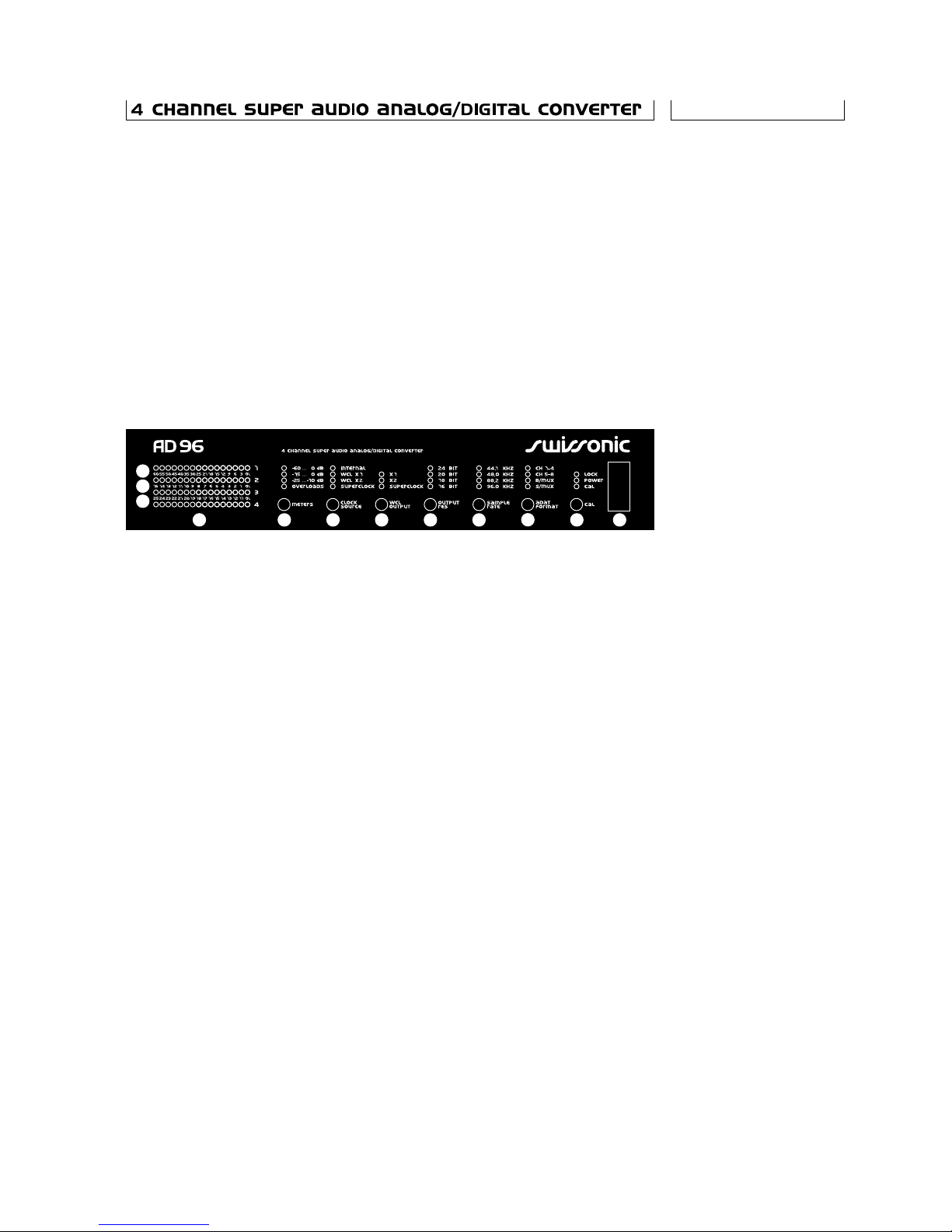
6 Clock source. Use this button to select the clock
source for the unit. The LEDs above it will display the
current clock source. The available clock sources are:
n
Internal. The unit will use it’s internal clock;
n
WCL x1. The unit will use the clock signal from the Wordclock
In connector. This clock must be in the 40 kHz…50 kHz range.
If the unit is set for 88/96kHz operation, it will multiply the
wordclock frequency by two before deriving it’s sample clock;
n
WCL x2. The unit will use the clock signal from the Wordclock
In connector. This clock must be in the 80 kHz…100 kHz range.
If the unit is set for 44/48kHz operation, it will divide the
wordclock frequency by two before deriving it’s sample clock;
n
Superclock. The unit will use the clock signal from the Wordclock
In connector. This clock must be 256 times the desired sample rate.
7 Wordclock output. Use this button to select
the clock format output on the Wordclock out
BNC socket on the rear panel. The LEDs above
it will display the current selection.
The available selections are:
n
x1. The unit will output a clock in the 40 kHz…50kHz range.
If the unit is set for 88/96 kHz operation, it will divide it’s internal
sample clock frequency by two before deriving the output;
n
x2. The unit will output a clock in the 80 kHz…100kHz range.
If the unit is set for 44/48kHz operation, it will multiply it’s internal
sample clock frequency by two before deriving the output;
n
Superclock. The unit will output a clock with a
frequency 256 times the internal sample rate.
8. Output resolution. Use this button to select the
desired output resolution. The LEDs above it will
display the current selection.
The available output resolutions are: 24 bits, 20 bits,
18 bits and 16 bits per sample.
The internal A/D converters always convert at 24 bit. Lower
resolutions are implemented using a dither generator with a
psycho-acoustic noise-shaping filter that minimizes the audibility
of the dithering process.
9 Sample rate. Use this button to select the desired
sample rate. The LEDs above it will display the
current selection. The available sample rates are
44,1, 48, 88,2 and 96 kHz. The sample rate
must be correctly selected even when the
unit operates on external clock.
10 Adat format. Use this button to select the desired
output Adat format. The LEDs above it will display
the current selection. The available formats are:
n
CH 1–4. This selection is available only with 44,1 and 48 kHz sample
rates. The unit will output the digital data on the Adat channel 1 to 4;
n
CH 5–8. This selection is available only with 44,1 and 48 kHz sample
rates. The unit will output the digital data on the Adat channel 5 to 8;
6

n
B/MUX. This is a special mode of recording that maps the full
24-bit data into multiple channels for use with recorders/systems
that only support 16-bit Adat resolution. For more information
see the Adat Formats section below;
n
S/MUX. This is the normal recording mode for 88,2 and 96 kHz
sample rates, providing the odd/even samples on alternate channels.
11 Calibrate. Use this button to initiate a calibration
cycle. During calibration the corresponding
LED will light. The unit automatically performs
a calibration cycle at power-on and every time the
CLOCK SOURCE or SAMPLE RATE are changed.
If the unit is set on external clock and not locked,
the CAL led will light continuously and the outputs
will be muted. A calibration cycle will automatically
be performed when the unit locks.
n
Lock LED. Indicates that the unit has locked to the external wordclock
input. It’s always turned off when internal clock operation is selected.
n
Power LED. Indicates that the unit is supplied with power and turned on.
12 Power switch. Turns the unit on and off. The front
panel settings are saved into non-volatile storage
when the power is turned off and subsequently
restored.
1 Earth terminal. Use this 4mm banana socket
to ground the chassis of the unit;
2 12 V AC jack. This is the power supply input.
Connect an approved power supply only;
3 Adat out Toslink optical connector. Keep it
plugged with a protective plug when not in use;
4 Wordclock out BNC connector. Use this output
if you need a master wordclock;
5 Wordclock in BNC connector. Supply here the
external wordclock;
6 AES/EBU output 1 XLR connector. Professional
format digital output of channels 1 and 2. See the
relevant section in the manual for interfacing with
coax units and/or Consumer format;
7 AES/EBU output 2 XLR connector. Professional
format digital output of channels 3 and 4.
8 Channel 1 input XLR. Fully balanced +4 dB analog
input. Pin 1=chassis ground, pin 2=positive, pin
3= negative. Clipping level: +20 dBu. See below
for interfacing with unbalanced / –10dB formats.
9–11 Channel 2–4 inputs XLR.
Rear Panel
Layout
7
1
234 5
67 911 8
10

Internal
clock
operation
External
clock
operation
1 Connect your analog source(s) using twisted
pair balanced cables provided with XLR connectors
to the INP1–INP4 inputs from the rear panel;
2 Supply the unit with power using the supplied
mains adapter through the jack marked +12 V AC
on the rear panel.
3 Connect the output marked as Adat out to your
digital equipment, using the supplied optic fiber
cable or similar, or to the AES/EBU outputs,
using a proper cable.
4 Power the unit using the Power button.
The Power led will light up.
5 Use the Clock Source button to select
internal clock operation, as shown by the
corresponding LED.
6 Use the Sample Rate button to adjust the
clock frequency at 44,1, 48,0, 88,2 or 96,0 kHz
as shown by the corresponding LEDs.
7 Use the Adat Format button to choose a recording
format that will match your selections of sample
rate and output resolution, and the capabilities
of your Adat machine.
8 After changing the sample rate and clock source,
the Cal LED will light momentarily, then turn off.
Once the LED turns off you can start recording.
Note: During the internal clock operation mode the
Lock LED is not lit, even if a valid external clock is
applied to the Wordclock input.
1 Connect your analog source(s) using twisted
pair balanced cables provided with XLR connectors
to the INP1–INP4 inputs from the rear panel;
2 Supply the unit with power using the supplied
mains adapter through the jack marked
+12 V AC on the rear panel.
3 Connect the output marked as Adat out to
your digital equipment, using the supplied optic
fiber cable or similar, or to the AES/EBU outputs,
using a proper cable.
4 Power the unit using the Power button.
The Power led will light up.
5 Use the Clock Source button to select external
clock operation, as shown by the corresponding
LED. If the clock source has a frequency of 44,1
or 48kHz, select x1 mode. If it has a frequency
of 88,2 or 96kHz, select x2 mode.
6 Use the Sample Rate button to adjust the clock
8

frequency at 44,1, 48,0, 88,2 or 96,0 kHz
as shown by the corresponding LEDs.
7. Use the Adat Format button to choose a recording
format that will match your selections of sample
rate and output resolution, and the capabilities
of your Adat machine.
8. Wait one or two seconds until the LOCK LED
lights up. This signals that the internal circuit has
successfully synchronized on your external clock.
9. After changing the sample rate and clock source,
the Cal LED will light momentarily, then turn off.
Once the LED turns off you can start recording.
When the unit is set on external clock and not
locked, the Cal LED will be continuously on,
and the outputs will be muted.
AD96 uses fully balanced, high CMR, transformerless
input buffers. In contrast with many cheap electronic
balanced configurations, AD96’s feature precision
matched «+» and «–» input impedances. This enables
the unit to preserve its high CMR and noise rejection
capabilities even with higher impedance sources
and/or long cable runs.
All inputs have protection circuits that clamp the
voltage to ±12,5 V. The input voltage range for both
«+» and «–» signals is ±12 V. There is no degradation
of performance anywhere within this range.
The balanced input configuration is used in professional
equipment for it’s ability to eliminate noise picked
by the long interconnects. Given the symmetrical
configuration of the balanced-line transmission chain,
all noise will couple equally in the two signal lines.
At the receiving end, the difference of the two input
voltages will always be the clean input signal. Any
asymmetry in the signal path will defeat the noise-
rejection of the balanced connection to a certain
degree, and should be avoided (Figure 1).
The differential input range of the AD96 is +20 dBu.
This means that a sinewave of +20 dBu amplitude
(7,75 Vrms) will produce a full-scale output signal
(0dBFS) digital output signal. This corresponds to a
peak differential input voltage of 11 V. Exceeding this
input level will cause the converter to clip (Figure 2).
Clipping obviously causes severe distortion of the
signal and should be always avoided. Clipping very
brief transients (1–2 samples -50us) is sometimes
Interfacing
with the AD96:
AD24 Analog
Inputs
Figure 1: Input
stage configuration.
AD96 Input
Levels
9
1
3
2
+12V Clamp
–12V Clamp
RFI
Filter
+
—
HighCMR
Diff Amp

considered acceptable. However, due to the high
dynamic range that the AD96 possesses, there is
no need to record at a level that will cause transient
clipping. A slight reduction in gain will avoid distorting
the signal and still leave ample dynamic range. Tran-
sient handling is best left for the mastering stage,
when the signal is finally mapped to 16 bits.
Unprocessed signal sources have peak to average
level ratios of up to 20 dB, so we recommend setting
the 0 VU level at -20 dBFS digital. Signals coming
from analog tape are already compressed, with a
lower peak to average ration. Higher line-up levels, up
to -14 dBFS for 0 VU, can be used.
For a balanced input, there are two possible clipping
situations:
nwhen the differential input voltage exceeds the
clip level, as described above;
nwhen the common mode plus half the differential
input voltage exceeds the maximum input voltage
range (±12 V for the AD 96).
The unit’s levels are selected to allow the full differen-
tial input voltage range plus a common mode range
of 6V to be accommodated without clipping. This
includes operation with one input tied to ground. A
larger common mode voltage will cause clipping. This
(rare) situation will not be signaled by the front-panel
Over LED, which is driven by a digital level detector.
The AD96 is designed to interface directly to pro-
fessional level (+4 dB) balanced output equipment.
The preferred type of connection is via a shielded,
twisted-pair cable, with the shield connected to the
chassis ground at both ends (Figure 3A). Connecting
the shield at both ends ensures proper protection
against RFI (radio-frequency interference), as well as
low frequency interference and should be employed
whenever possible.
Some balanced equipment uses TRS inch jacks
instead of the XLR connectors. They are equivalent,
Figure 2: Clipping
example.
Connecting
the AD96 to
balanced output
equipment
Figure 3: Preferred
balanced cable setup
10
Out of scale input signal
Clipped output signal
+ Clip level
– Clip level
red
black
shield
red
black
shield
red
black
shield
red
black
shield
Female 1 1
1
33
3
2 2
2
two conductor shielded twisted cable
Male
Male
A. XLR to XLR connection
. TRS to XLR connectionB

with the tip corresponding to pin 2 of the XLR («posi-
tive» or «hot» signal), the ring corresponding to pin 3
(«negative» or «cold» signal) and the sleeve corre-
sponding to pin 1 («ground» or «shield»). The cable
should be configured as shown in Figure 3B.
The input level of the AD96 is selected for compati-
bility to most «pro-level» output gear. There is one
notable exception: Some (older) analog tape machines
don’t have output level trims, and provide peak levels
well in excess of +20 dBu, especially when used with
high level recordings. For these cases, a passive
attenuator, or pad should be used.
At the other end of the spectrum, the «semi-pro»
(-10dB) gear will not have enough output to fully utilize
AD96’s dynamic range. AD96 provides a way to
increase the input buffer gain by circa 11 dB by chang-
ing jumpers from the PCB. Note, the «+4» really
means +4 dBu, while the «-10» means -10 dBV.
0 dBV equals roughly 3 dBu, so the difference be-
tween «+4» and «-10» is actually 11 dB.
To change gains, open the case and move the jumpers
corresponding to the channel for which you need a
gain boost from position 1-2 to position 2-3. The
jumpers are labeled JP1-8, corresponding to channels
1 to 4 (JP1 and 2 for channel 1, etc).
Mixing balanced and unbalanced equipment is generally
a bad idea, as the two systems aren’t compatible.
Such mixing is the most frequent cause of hum
in audio systems. However, in a non-ideal world, it
cannot usually be avoided.
The best way to do it, albeit the most expensive, is to
use an isolating transformer (Figure 4). It can also be
used to raise the signal to «pro» levels (+12 dB of
voltage gain is achieved by a 4:1 transformer).
The alternative to transformer coupling is to use a
special cable, set up as shown in Figure 5. If you get
hum, try the ground-lifted version in Figure 6. You will
almost certainly need to boost the input gain of
Level Matching
Connecting
to unbalanced
equipment
Figure 4: Using an
isolating transformer.
Figure 5: Unbalanced
to balanced cable
setup (preferred).
11
red
black
red
shield
two conductor shielded twisted cable
red
black
two conductor shielded twisted cable
Male
3
1
2
Male
A: RCA to XLR connection
B: TS to XLR connection
3
1
2
red
black
shield
black
Case lug
mat connect
to chassis
(not required)
Not
connected
to chassis
(plastic jack)
chassis
grounded
to pin1
earth grounded
metal enclosure
BalancedUnbalanced
1
2
3
Transformer

the AD96, as shown above, as most non-balanced
equipment has low output level.
Sometimes, balanced connections tend to hum.
This is either a grounding problem, or a ground loop
problem. For a detailed explanation, check the
«Where does the hum come from» application note.
In a nutshell, to eliminate the hum, try the following:
Check that all gear is properly earthed. Equipment
with a line plug is usually earthed through that. Check
the earth on the mains socket; Equipment with out-
board power supplies (like the AD96) is not earthed
via its power connection. It must be grounded else-
where, either through the cable shield to a properly
earthed unit, or directly, using the socket on the back.
Try toggling ground-lift switches on related units. Use
this step with caution and check thoroughly, as it can
induce problems in other parts of the system.
If all else fails, you may need to lift the shield on one
end of the interconnections. If you already have an
established shield-lifting practice, use that. If not, we
recommend lifting the ground at the transmitter end.
This will provide better RFI protection. Try the cable
configuration in Figure 7 A, B, C – in that order.
12
red
black
red
shield
two conductor shielded twisted cable
red
black
two conductor shielded twisted cable
Male
3
1
2
Male
A: RCA to XLR connection
B: TS to XLR connection
3
1
2
red
black
shield
black
1
3
2red
black
shield 3
1
2
red
black
shield
two conductor shielded twisted cable
Female Male
A: Shield connected to chassis contact on source equipment
1
3
2red
black
shield 3
1
2
red
black
shield
two conductor shielded twisted cable
Female Male
B: Shield connected via decoupling cap. C=1
1
3
2red
black
shield 3
1
2
red
black
shield
two conductor shielded twisted cable
Female Male
C: Shield lifted on source equipment
0nF film type
Figure 6: Unbalanced
to balanced cable
setup (ground lifted)
Avoiding hum
Figure 7: Hum fixing
techniques

The level meters of the AD96 were designed to sup-
port the user throughout the recording process: It
helps accurately set the recording level before record-
ing (using the high-resolution -15…0 and -25…-10
scales for lineup), monitor the level during recording
(using the high dynamic range –60..0 scale), and
ensure that no or limited clipping occurred (by check-
ing the overs counter after the recording).
The level meters use high-accuracy digital peak
detectors, and format the output according to the
front panel setting. With all settings, the leftmost LED
works as a channel active indicator, lit whenever the
signal exceeds -60 dBFS, while the rightmost red LED
works as an over indicator, lit when clipping occurs.
When using the three metering modes, each LED
lights when the peak signal level exceeds the level
written next to it. The thresholds are accurate to
0,1 dB.
An overs counter is maintained by the unit at all times.
Whenever the clipping limit is exceeded, the overs
counter is incremented. When the overs mode is
selected, the contents of the overs counter is dis-
played on an exponential scale; for one over a single
led will light, for two (21) two leds will light, while for
1024 ( 210) eleven leds will light. The 14 leds allow
the display of values in the range 0…213=8192.
When more than 8192 overs are detected, all leds
will light. The over counter is cleared when the unit is
powered up, and whenever the cal button is pressed.
The normal sequence of operations for recording will
be as follows: first, route a calibrated tone to the
AD96 inputs. Select the -25…-10 scale, and adjust
the level on the driving device until the LED corre-
sponding to the desired level (e.g. -20 dBFS) just
begins to light. Then select the normal (-60…0) scale
for monitoring the recording and press Cal to reset
the overs counter (and ensure maximum performance
of the ADCs). Start recording. At the end, select the
overs mode and check the numbers. If just 2–3 LEDs
are on, things are probably ok, but if more than a few
light, the recording level was clearly too high.
AD96 can work with either internal or external clocking.
Each mode of operation was designed to respond
to specific demands. When you use a single AD96
unit, that needs not be synchronous with another
equipment, the best performance is obtained using
the internal clock mode.
Level Meters
Clocking
13

If you need to synchronize one or more AD96 units,
or a combination of AD96 units and other equipment,
then you will need a master clock source for the whole
system. If you have such a clock source then all you
have to do is to set all AD96 units on external clock,
and feed them from the clock source.
If you do not have a master clock source, then one of
the AD96 units can provide it for you. For this unit set
the Clock source to internal. Choose the value of the
wordclock output by this unit depending on the other
equipment you want to synchronize. AD96 is able to
supply a wordclock of x1, x2, x256 or half the sample
rate. All other AD96 units must be set on external
clock operation using the sample multiplication factor
as the master unit. Use the table below to determine
what wordclock rates will an AD96 output or lock on to:
Wordclock Sample rate
setting 44,1 kHz 48,0 kHz 88,2 kHz 96,0 kHz
x1 44,1 kHz 48,0 kHz 44,1 kHz 48,0 kHz
x2 88,2 kHz 96,0 kHz 88,2 kHz 96,0 kHz
Superclock 11,289 MHz 12,288 MHz 22,579 MHz 24,576 MHz
The ability to operate at 88/96kHz while generating
and locking to 44/48kHz word clock signals becomes
essential when the unit’s Adat output is used, as most
Adat-compatible equipment does not support 88/96
word clocks, even if it can be made to process 88/96
data using the S/MUX feature.
For maximum flexibility, the input and output word-
clock formats are independently selectable. The AD96
can untangle any wordclock format problem.
A common requirement in larger installation is to
distribute the master clock from one unit to several
other. The Wordclock inputs and outputs of the AD96
were designed to simplify this as much as possible.
When using low-frequency (x1, x2) clocks, the output
of one AD96 can properly drive up to eight other units
using a simple bus configuration. No termination is
necessary if the cable length is kept below 10 m.
RG58U cable and BNC «T» connectors are all that is
required.
The higher frequencies of the Superclock mode preclude
the use of the bus configuration. A single unit can be
driven from the AD96 output. However, there is no
performance gain in using Superclock with the AD96,
so if several units must be synchronized to a Super-
Wordclock
frequencies accepted
or generated by
the AD96
Clock
distribution
14

clock source, one unit can be used to convert to x1 or
x2 mode and the output of that unit fed to the other.
Figures 8, 9, 10 and 11 show examples of clocking
configurations.
The AD96 will significantly reduce jitter present on it’s
Wordclock input before using that clock and will out-
put the «cleaned-up» version of the wordclock to the
respective output. See Figure 12 for the typical jitter
reduction characteristic.
The Adat lightpipe in itself is a good way of moving 8
channels of 24-bit, 44 or 48 kHz data from A to B. How
various pieces of gear interpret this data, that’s a dif-
ferent story. Original Adat MDMs only support 16 bit
of each channel, the same as older Adat soundcards.
The newer soundcards will input and output all 24bits.
Adat MDMs are available with 20-bit recording depth.
There are two sides of mapping 24/96 data to various
Adat equipment: mapping the sample rate and map-
ping the bit depth. To map the double sample rate, the
obvious solution of using two 48 kHz channels for
each 96kHz channel will work smoothly. This way, the
Figure 8: A single
AD96 is slaved to an
external 48 kHz clock
source (upper). The
AD96 can be used to
convert from a 96 kHz
source to the 48 kHz
needed by an Adat
MDM (lower).
Figure 9: Multiple units
are slaved to an exter-
nal clock source.
Figure 10: Multiple
units are synched
together, using the
first unit’s internal
clock as reference.
Figure 11: Daisy chain
configuration used
when locking to super-
clock.
Jitter reduction
ADAT and 24/96
Figure 12: Typical
jitter attenuation
characteristic
15
out
in
AD96
Wordclock
Clocksource = WCL x1
out
in
AD96
Wordclock
Clocksource = WCL x2
WCL out = x1
Clocksource
48 kHz
Clocksource
96 kHz 48 kHz
Adat MDM
Clocksource
96kHz
out
in
AD96
Wordclock
Clocksource = WCL x2
out
in
AD96
Wordclock
Clocksource = WCL x2
out
in
AD96
Wordclock
Clocksource = WCL x2
To other equipment
out
in
AD96
Wordclock
Clocksource = int
WCL out = x2
out
in
AD96
Wordclock
Clocksource = WCL x2
Clockmaster slave1
up to10 m
slave n (up to 8 units)
out
in
AD96
Wordclock
Clocksource = WCL x2
To other equipment
Clocksource
superclock
out
in
AD96
Wordclock
Clocksource = super
WCL out = super
out
in
AD96
Wordclock
Clocksource = super
WCL out = super
out
in
AD96
Wordclock
Clocksource = super
WCL out = super
To other equipment
Up to 5m Up to 5m
out
Jitterattenuation (dB)
0
5
10
15
20
25
30
35
0.1 1 10 100
Jitterfrequency (Hz)
1K

recording equipment operates without modification.
This solution has been specified to a high degree of
generality by the S/MUX standard. In short, the first
channel of 96kHz data goes to Adat channels 1 and 2,
the second to Adat channels 3 and 4 etc. The AD96
supports S/MUX by default whenever operating in
88/96 mode.
Mapping the bit depth can take two approaches. The
«exact» approach is to use a similar scheme and route
the lower 8 bits of each sample to a second channel.
This will again use two Adat channels for each input
channel. The AD96 supports this option with its
B/MUX feature.
Another way is to use the dithering/noise shaping
function of the AD96 and actually store a lower num-
ber of bits. While at 16 bits an increase in noise is
apparent, this is an excellent solution when 20 bits can
be stored. The difference between true 24 bits and
mapped 20 bits is virtually undetectable. This solution
has the advantage that it uses half the number of
channels and storage space.
The two methods can be used simultaneously, thus
allowing 24/96 recording on 16/48 equipment. When
B/MUX and S/MUX are used together, only two chan-
nels (1 and 2) are output on the Adat interface. Data
for channels 3 and 4 will still be available at the
AES/EBU output.
n
24/96 to computer interface. A straightforward
example of using the S/MUX feature. Each four
input channels use one Adat port. AD96 settings:
Sample rate: 88 or 96, B/MUX: off, S/MUX: on,
Output resolution: 24 bits.
n
24/48 to 16-bit recorder. Each four input channels
use one Adat port. AD96 settings: Sample rate:
44 or 48, B/MUX: on, Output resolution: 24 bits.
n
24/96 to 16-bit recorder. Only two channels are
supported on the Adat output. AD96 settings:
Sample rate: 88 or 96, B/MUX: on, S/MUX: on.
In this mode, an old Adat machine is transformed
into a dandy DVD mastering recorder. Audio goes
to Adat via the AD96, then at the mastering house
it gets loaded on the computer using their Adat
and a soundcard with compatible driver.
Compare the price to a 24/96 DAT.
n
24/96 to 20-bit recorder. Four channels can be
recorded for each Adat input. The 24-bit data is
dithered down to 20 bits before recording using
Application
examples
16

S/MUX. AD96 settings: Sample rate: 88 or 96,
B/MUX: off, S/MUX on, Output resolution: 20
bits. In 96 kHz mode, there’s plenty of non-audible
spectrum (between 20 and 40 kHz) to place the
dither, so the difference between this mode and
real 24 bits is non-decelable. AD96, together with
the matching DA96 and 20-bit MDMs can be used
to build a budget-conscious mutitrack recording
system with unmatched performance.
The unit provides two AES/EBU outputs, which trans-
mit the audio data from all channels at all times. The
frequency of operation of the AES/EBU outs always
equals the internal operation frequency of the AD96.
As shipped by the factory, the unit will output data in
the «professional» format, with 110 Ωbalanced, 5 Vp-p
signal level.
Jumpers inside the unit allow the «consumer» format
and/or output levels to be selected. To select con-
sumer format for both outputs, remove jumper JP13.
To select consumer levels and impedance (75 ohm,
0,5 Vp-p) place jumpers JP10 and 11 in the 2–3 posi-
tion. An adapter that transforms the balanced
AES/EBU out to the unbalanced S/PDIF coax inter-
face is shown in figure 14.
Figure 13: Mapping of
converter data to Adat
channels for various
operation modes.
AES/EBU
outputs
Figure 14: Adapter
cable for connecting to
S/P DIF.
Figure 15: Adapter
cable for AES/EBU
over 75 ohm coax.
17
Converter data
CH 1 CH 2 CH 3 CH 4
MSB MSB MSB MSBLSB LSB LSB LSB
CH 2 CH 3 CH 4 CH 5 CH 6 CH 7 CH 8
H 1, N+1
H 1, N
M 1, N+1
M 1, N
L 1, N+1
L 1, N
H 2, N+1
H 2, N
M 2, N+1
M 2, N
L 2, N+1
L 2, N
H 3, N+1
H 3, N
M 3, N+1
M 3, N
L 3, N+1
L 3, N
H 4, N+1
H 4, N
M 4, N+1
M 4, N
L 4, N+1
L 4, N
H 1, N
H 1, N
H 1, N
H 1, N
L1, N+1
M 1, N
M 1, N
M 1, N
M 1, N
L 1, N
L 1, N
H 2, N M 2, N L 2, N
H 2, N
H 1, N+1
H 1, N+1
M 2, N
M 2, N
M1,N+1
M1,N+1 H 2, N
M 3, N L 4, NH 3, N
H 3, N
H 2, N
M 3, N
M 2, N
M 2, N L 4, N H 2, N+1
H 4, N
M2, N+1
M 4, N
L 2, N+1
L 4, N
H 4, N M 4, N
H 2, N+1 M2,N+1
H 1, N M 1, N L 1, N
H 3, N
L 1, N
L 1, N
M 3, N L 3, N H 3, N+1
H 2, N
M3,N+1
M 2, N
L 1, N+1
L 2, N
L 2, N
L 3,N+1
H 3, N M 3, N
L 4, NH 4, N
L 4, N
L 2, N
M 4, N
L 3, N H 4, N
H4,N+1 M4, N+1
M 4, N
L 2, N+1
L 4, N
L 4, N
L4,N+1
CH1
000000000000
000000000000
0
0
0
0
0
0
0
0
0
0
0
00
0
0
0
0
0
0
0
0
0
0
0
Adat out
CH1–4
CH5–8
S/MUX
B/MUX
S/MUX
B/MUX
3
1
10 nF
film
75 Ωcoax
2
10 nF
film
75 Ωcoax
3
1220 Ω
2

Calibration
Some users prefer to use the professional format with
75ohm coax cable and BNC connectors, due to the
reduction in cost, ease of patching and more reliable
operation. The AD24 supports this mode as well. An
adapter from the balanced XLR to 75ohm BNC is
shown in figure 15. No jumper changes are required.
The high-resolution analog-digital converters used in
the AD96 need to be calibrated to minimize noise and
distortion. Calibration is required in the following situa-
tions:
n
after each power-on of the unit;
n
after each change of internal / external clock
n
source selection;
n
after each change of the sample rate between
44,1/48,0/88,2/96,0 kHz.
The AD96 will automatically perform a calibration
cycle whenever one of these events occur. It is
advised that the AD96 be calibrated after the device
has reached thermal equilibrium to maximize per-
formance. This is not required, but will give the peace
of mind of extracting the maximum performance for
that critical recording.
To initiate a calibration, press the Calibrate button and
wait until the Cal LED turns off. The unit automatically
performs a calibration cycle after power-on, or when
settings are changed, as indicated by the Cal LED.
During calibration, all outputs are muted. When the
unit is set on external clock and not locked, the Cal
LED is lit continuously, and the outputs are muted.
After locking, a calibration cycle is automatically per-
formed, then the outputs become active.
18

Resolution
Resolution: 24 bits
Resolution reduction: to 20, 18 or 16 bits
Using dithering with psycho-
acoustic noise shaping
Dynamic Performance
Dynamic Range 118 dB (A-weighted)
113 dB (unweighted)
Total Harmonic
Distortion + Noise -100 dB (-1 dBFS input level)
20…20000 Hz
(-95 dB -20 dBFS input level)
(-53 dB (-60 dBFS input level)
Total Harmonic Distortion: 0,001% (-1 dBFS input level)
Interchannel Phase
Deviation: 0,1 deg
Interchannel Isolation: 110 dB
Analog Inputs
Connector type: XLR, 1=GND; 2=Hot;
3=Cold, fully balanced
Full-scale differential
Input Voltage: +20 dBu
22 Vp-p
7,75 Vrms
Common Mode
Input Impedance: 6000 Ω
Differential Input
Impedance: 24000 Ω
Input Voltage Range: ±12 Volts each input
Common Mode
Rejection Ratio: 50 dB @ 120 Hz
35 dB @ 20 kHz
Gain options: Internal jumpers increase
gain by 11 dB, with a
corresponding decrease
in full-scale level
Specifications
19

Frequency Response
Passband: 20–44200 Hz @ -0,1dB,
FS=96,0 kHz
20–40600 Hz @ -0,1dB,
FS=88,2 kHz
20–22100 Hz @ -0,1dB,
FS=48,0 kHz
20–20300 Hz @ -0,1dB,
FS=44,1 kHz
Passband Ripple: 0,01 dB
Low cut frequency: 1,5 Hz -3dB
Stopband: 53,2 kHz @ FS= 96,0 kHz
49.0 kHz @ FS= 88,2 kHz
26.6 kHz @ FS= 48,0 kHz
24.5 kHz @ FS= 44,1 kHz
Stopband Attenuation: 117 dB
Group Delay: 350 s @ FS= 96,0 kHz
385 s @ FS= 88,2 kHz
700 s @ FS= 48,0 kHz
770 s @ FS= 44,1 kHz
Group delay variation
vs. Frequency: 0 s
Wordclock input
Type: BNC, optically isolated
Impedance: 10 kΩ
Input level: TTL
Lock range: 40–50 kHz, x1 mode
80–100 kHz, x2 mode
10,24–12,80,
20,48–25,60 MHz
Superclock mode
Wordclock output
Type: BNC
Impedance: 50 Ω
Output level: TTL
Short circuit current: 50 mA
Driving capability: up to 10m, up to 8 units
x1, x2 mode;
up to 5m, single unit
Superclock mode
20

Internal clock
Frequency error: <100 ppm over
temperature range
Jitter: <50 ps rms
PLL section
Static phase error: <100 ns over
temperature range
Internally generated jitter: <100 ps rms
Jitter attenuation: 25 dB @ 500 Hz
40 dB @ 5000 Hz
AES/EBU outputs
Type XLR transformer isolated
Impedance 110 Ωbalanced
Output Voltage 5 Vp-p into 110 Ω
Format Professional
Jumper options Internal jumpers select
75 Ωimpedance,
0,5 Vp-p output level
and consumer format
Adat Output
Type: Toslink optical
Format: normal, B/MUX, S/MUX
Power Supply Requirements
Input Voltage: 12 V AC +10/-15%
Maximum Current
Consumption: 1,2 A
Other information
Unit Size: 42,5@217@230 mm
Unit weight: 1,5 kg
Operating Temperature
Range: 0–40 ºC
Operating Humidity 0–90% non-condensing
21
Table of contents
Other swissonic Media Converter manuals