Positron BRX User manual

BRX Power Injector Installation Guide 180-0192-001-R01
Broadband Reach eXtender
Power Injector
(BRX-PWR)
Installation Guide
Document: 180-0192-001
March 2020

BRX Power Injector Installation Guide 2 180-0192-001-R01
Publication Information
©2020 Positron Access Solutions Corporation. All rights reserved.
Broadband Reach eXtender (BRX) Power Injector Quick Installation Guide
Publication date: March 2020
Printed in Canada
Published By
Positron Access Solutions Corporation
5101 Buchan Street, Suite 220
Montreal, Quebec, Canada
H4P 2R9
Telephone US and Canada: 1-888-577-5254
International: +1-514-345-2220
Product names, other than Positron's, mentioned herein may be trademarks and/or registered
trademarks their respective owners.
Disclaimer Notice
Although Positron Access Solutions Corp. has made every effort to ensure the accuracy of the
information contained herein, this document is subject to change.

BRX Power Injector Installation Guide 3 180-0192-001-R01
Table of Contents
1Introduction.................................................................................................................................5
2Principles of Operation and Specification Summary................................................................6
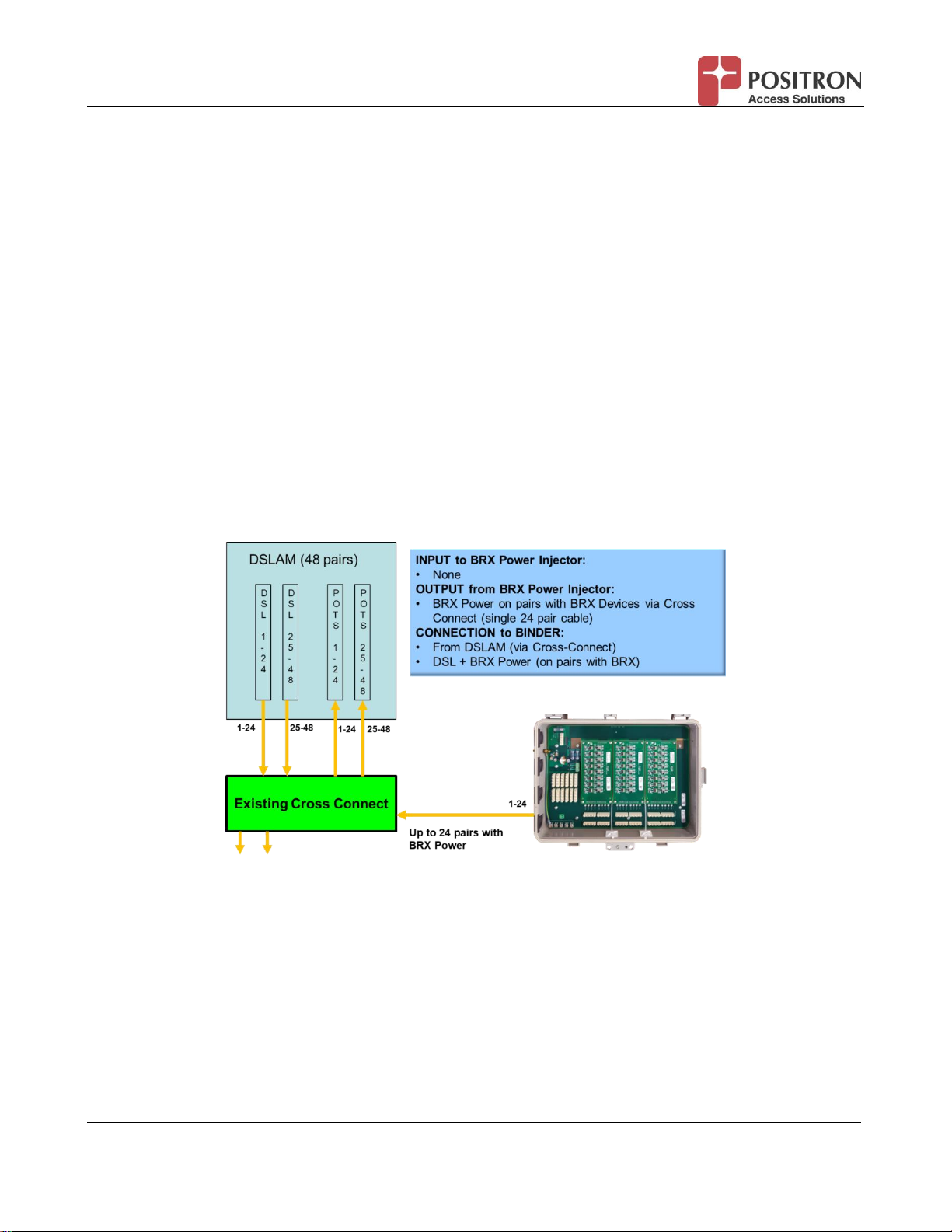
2.1 Connecting the BRX Power Injector to the DSLAM via a cross-connect...................................7
2.2 Connecting the BRX Power Injector Directly to the DSLAM .....................................................7
2.3 Combining POTS pairs with BRX Power Injector pairs directly to the DSLAM..........................8
3Quick Installation: Step-by-step Instructions............................................................................9
3.1 Connecting the Power Source..................................................................................................9
3.1.1 Local -48Vdc Source......................................................................................................10
3.1.2 Local 110-220Vac Source..............................................................................................11
3.1.3 Express (RFT-V) Power Pairs ........................................................................................15
3.2 Grounding the BRX Power Injector ........................................................................................16
3.3 Using Bypass Section for POTS pairs....................................................................................17
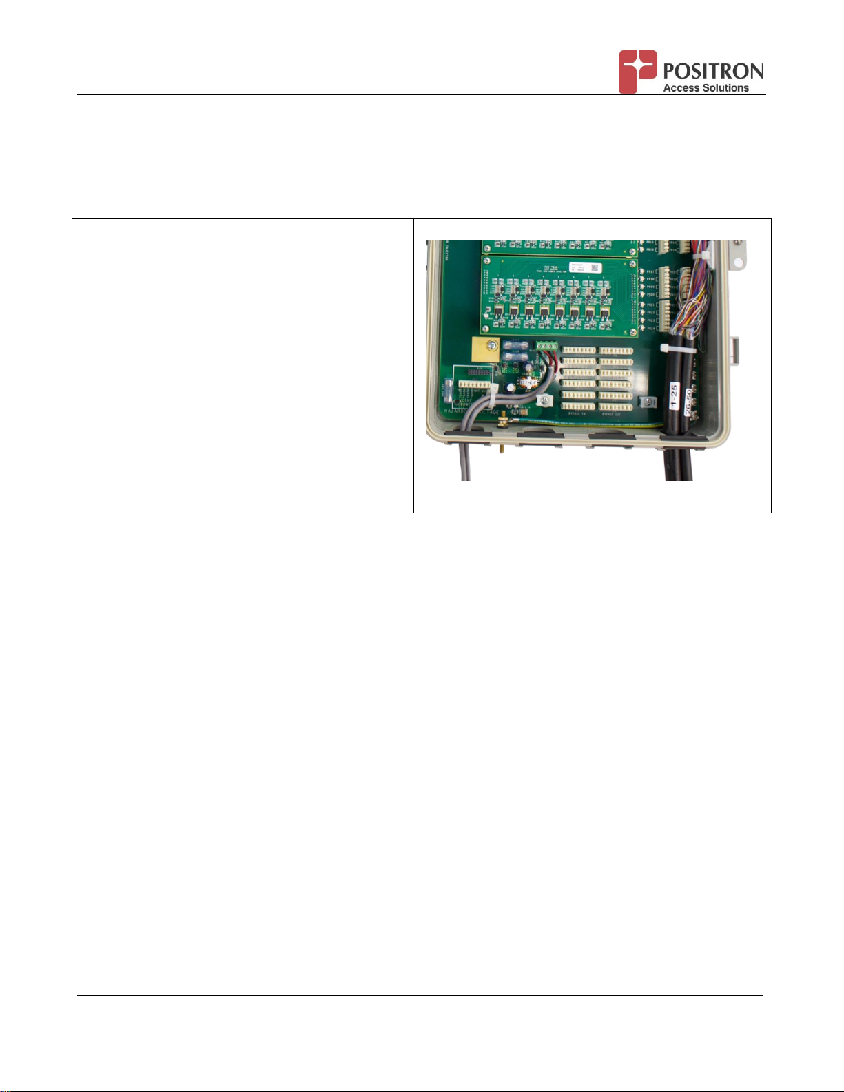
3.4 Installing Copper Cables into BRX Power Injector..................................................................18
3.5 Sealing the Rubber Grommets before Installation..................................................................19
3.6 Installing additional BRX-PWR- M Module(s).........................................................................20
4BRX Power Injector Visual Indicators and Troubleshooting Guidelines...............................23
4.1 LED Descriptions...................................................................................................................23
4.2 Troubleshooting Steps for the BRX Power Injector.................................................................24
5Using BRX Power Injector with Popular DSLAM Platforms...................................................29
5.1 Adtran 1148V.........................................................................................................................29
5.2 Calix E3-48-r2........................................................................................................................30
5.3 Nokia 7330 ISAM...................................................................................................................30
5.4 Huawei MA5116S ..................................................................................................................31
6Regulatory Compliance and Safety .........................................................................................32
7Warranty and Customer Service..............................................................................................34

BRX Power Injector Installation Guide 4 180-0192-001-R01
List of Figures
FIGURE 1: BRX POWER INJECTOR –HIGH-LEVEL VIEW 5
FIGURE 2: INSIDE THE BRX POWER INJECTOR 6
FIGURE 3: CONNECTING THE BRX POWER INJECTOR TO THE DSLAM VIA A CROSS-CONNECT 7
FIGURE 4: CONNECTING THE BRX POWER INJECTOR DIRECTLY TO THE DSLAM 8
FIGURE 5: USING THE BRX POWER INJECTOR TO COMBINE POTS AND BRX POWER PAIRS 8
FIGURE 6: AC CABLE PRE-INSTALLED AND TERMINATED IN THE BRX POWER INJECTOR 11
FIGURE 7: CONNECTING THE BRX POWER INJECTOR TO AN ADTRAN 1148 SERIES DSLAM 29
FIGURE 8: CONNECTING THE BRX POWER INJECTOR TO A CALIX E3-48-R2 DSLAM 30
FIGURE 9: CONNECTING THE BRX POWER INJECTOR TO A NOKIA 7330 ISAM POTS SPLITTER 31
FIGURE 10: CONNECTING THE BRX POWER INJECTOR TO A HUAWEI MA5116S SERIES DSLAM 31
List of Tables
TABLE 1: BRX POWER INJECTOR POWERING OPTIONS AND ORDERING CODES 9
TABLE 2: CONNECTING A LOCAL -48VDC POWER SOURCE TO THE BRX POWER INJECTOR 10
TABLE 3: CONNECTING A LOCAL 110-220VAC POWER SOURCE TO THE BRX POWER INJECTOR 14
TABLE 4: CONNECTING RFT-V EXPRESS POWER PAIRS TO THE BRX POWER INJECTOR 15
TABLE 5: GROUNDING THE BRX POWER INJECTOR 16
TABLE 6: USING THE POTS BYPASS SECTION OF THE BRX POWER INJECTOR 18
TABLE 7: CONNECTING BRX POWER PAIRS TO THE CABLE BINDER FEEDING INTO POTS CONNECTOR OF DSLAM 19
TABLE 8: APPLYING A SILICON SEALANT TO THE RUBBER GROMMETS IN USE 20
TABLE 9: INSTALLING ADDITIONAL BRX-PWR-M MODULES IN BRX POWER INJECTOR 22
TABLE 10: POWER LED 23
TABLE 11: BRX POWER PAIR STATUS LED 23
TABLE 12: TROUBLESHOOTING THE BRX POWER INJECTOR 28

BRX Power Injector Installation Guide 5 180-0192-001-R01
1 Introduction
The Positron Broadband Reach eXtender (BRX) devices get their power from the -48Vdc sealing
current usually found on DSL + POTS pairs. Due in part to the migration away from POTS to VoIP or
data-only services (sometimes referred to as “naked DSL”), DSL pairs may lack a -48Vdc sealing
current. The increased use of bonded xDSL pairs means that the second (2nd) pair is often without
sealing current. Positron designed the BRX Power Injector to inject the -48Vdc sealing current to
power the BRX devices installed on xDSL pairs requiring amplification.
The BRX Power Injector installs adjacent to the DSLAM where its power pairs connect to the POTS
port of the DSLAM where the CO telephone pairs normally terminate. The DSLAM then acts as a
combiner to overlay the -48Vdc sealing current onto the DSL pair. The BRX Power Injector is
available in 8, 16 or 24 pair configurations packaged in a UL-rated IP65 enclosure as per Figure 1.
Figure 1: BRX Power Injector –high-level view
The approximate dimensions of the BRX Power Injector are: 16.35” High x 13.0“ Wide x 3.85” Deep or
415 mm H x 333 mm W x 98 mm D. The enclosure includes flanges to easily mount the BRX Power
Injector on a pole, stake or on the back of popular pedestals.

BRX Power Injector Installation Guide 6 180-0192-001-R01
2 Principles of Operation and Specification Summary
The BRX Power Injector offers the following features:
Wall-mount and Pole Mount options
Can be ordered in 8, 16 or 24 pairs configurations
Field upgradable by installing up to a total of three (3) 8-pair power modules
Flexible Power Input
Local -48Vdc, or
Local 110-220VAC with factory installed AC-DC Converter, or
Express (line) Powering: 1 or 2 pairs with factory installed: GE or ALPHA Down
Converter (±190Vdc to -48Vdc)
Output Pairs with BRX Power
Connected via standard 110 punch-down connectors
Diagnostics:
Status LED per pair: indicates Power to the BRX and Error Condition (if any)
The following block diagram (figure 2) highlights the inside of the BRX Power Injector:
Figure 2: Inside the BRX Power Injector
The power source of the BRX Power Injector can either be a local -48Vdc source, a local 110-220Vac
or express power pairs. A single express power pair is sufficient to power 24 pairs with BRX devices.
Support for a second express power pair is included whenever redundancy is required. When using a
local AC input, the BRX Power Injector is factory installed with a 110-220VAC to -48VDC power
supply. When using express pairs, the BRX Power Injector is factory installed with a down converter
module (±190Vdc to -48Vdc) from either Alpha Technologies or from GE Lineage. Note: You need to
make sure to use the same brand of up converter (-48Vdc to ±190Vdc) and down converter for full

BRX Power Injector Installation Guide 7 180-0192-001-R01
compatibility.
The BRX Power Injector delivers a -48Vdc (0.5w) sealing current for each pair where a BRX
amplification device is installed. Looking at figure 2, there are three (3) 8-pair power modules
installed. The output of these power modules connects to the pairs from the POTS port of the DSLAM
via a standard 110 punch down block (top left section of the picture. It is possible to connect two (2)
24-pair cables from the DSLAM. The opening allow for up to two cables for a total of 24 pairs
powered from the BRX Power Injector and the remaining pairs passed through untouched.
The BRX Power Injector typically connects to the DSLAM POTS port(s) via a nearby cross-connect
box. Its flexible design also supports a direct connection to the DSLAM. It is also possible to use the
BRX Power Injector as a basic cross-connect when having to combine POTS and BRX Power pairs
on the same cable binder(s) and in the absence of a cross-connect.
2.1 Connecting the BRX Power Injector to the DSLAM via a cross-connect
When connecting the BRX Power Injector via an existing cross-connect, a single 24-pair cable
connects to the BRX Power Injector since the cross-connect will then connect to the pairs that need
the -48Vdc sealing current into the DSLAM.
Figure 3: Connecting the BRX Power Injector to the DSLAM via a cross-connect
2.2 Connecting the BRX Power Injector Directly to the DSLAM
It is possible to connect the BRX Power Injector directly to the DSLAM where there is no cross-
connect at the location. In this case, it is important to assign the power to those pairs where a BRX
device is present. You will also need to make sure you select the proper cable binder matching each
amplified DSL pairs.

BRX Power Injector Installation Guide 8 180-0192-001-R01
Figure 4: Connecting the BRX Power Injector directly to the DSLAM
2.3 Combining POTS pairs with BRX Power Injector pairs directly to the DSLAM
While it is preferable to use an available cross-connect the BRX Power Injector includes a simple
cross-connect made up of 24 input pairs and 24 output pairs accessible via punch-down blocks.
POTS pairs in input to the BRX Power Injector shall be punched into the bypass section. The output
blocks of the bypass section allow you to mix POTS and BRX Power pairs into their respective binder
cable that connect to the POTS ports of the DSLAM.
Figure 5: Using the BRX Power Injector to combine POTS and BRX Power pairs
Important Note: the BRX Power Injector supports a maximum of 24 POTS pairs as input to the
bypass section. An external cross connect device shall be used when there are more than 24 POTS
pairs to combine with the BRX Power pairs.

BRX Power Injector Installation Guide 9 180-0192-001-R01
3 Quick Installation: Step-by-step Instructions
This section provides a detailed procedure to connect the power source to the BRX Power Injector.
You will also find a procedure to connect POTS pairs directly to the BRX Power Injector in the
absence of a nearby cross-connect. Finally, you will find a procedure to connect the BRX Power pairs
to the cable binder(s) connecting to the POTS port of the nearby DSLAM.
3.1 Connecting the Power Source
The BRX Power Injector offers a choice of three (3) power source:
Power Source
BRX Power Injector Ordering Codes
Local -48Vdc
BRX-PWR-8: 8-pair BRX Power Injector with local -48Vdc input
BRX-PWR-16: 16-pair BRX Power Injector with local -48Vdc input
BRX-PWR-24: 24-pair BRX Power Injector with local -48Vdc input
Local 110-220Vac
BRX-PWR-8-AC: 8-pair BRX Power Injector with local 110-220Vac input
BRX-PWR-16-AC: 16-pair BRX Power Injector with local 110-220Vac input
BRX-PWR-24-AC: 24-pair BRX Power Injector with local 110-220Vac input
Express Pairs
(RFT-V ±190V)
BRX-PWR-8-A: 8-pair BRX Power Injector with ALPHA Express Power input
BRX-PWR-16-A: 16-pair BRX Power Injector with ALPHA Express Power input
BRX-PWR-24-A: 24-pair BRX Power Injector with ALPHA Express Power input
BRX-PWR-8-G: 8-pair BRX Power Injector with GE Express Power input
BRX-PWR-16-G: 16-pair BRX Power Injector with GE Express Power input
BRX-PWR-24-G: 24-pair BRX Power Injector with GE Express Power input
N/A
BRX-PWR-M: 8-pair BRX Power Module to increase the pair capacity to a
maximum of 24 pairs (3 x BRX-XLR-M)
Table 1: BRX Power Injector Powering Options and Ordering Codes

BRX Power Injector Installation Guide 10 180-0192-001-R01
3.1.1 Local -48Vdc Source
The BRX Power Injector gets its power from a local -48Vdc source. It operates from a single -48Vdc
power source and supports a second (2nd) power feed for redundancy.
Using the leftmost opening, slice open the
rubber grommet and insert one or two DC
Power cable. Be careful when cutting an
opening in the rubber grommet since you will
need to apply a silicon sealant in step 2.
NOTE: you can refer to steps 7 to 12 for the
installation of the AC Power Cable option for
more details about inserting the cable through
the rubber grommet.
Connect the black wire(s) to the screw-in
terminal post(s) labeled as -48Vdc.
Connect the red wire(s) to the screw-in terminal
post(s) labeled as Return.
Table 2: Connecting a local -48Vdc power source to the BRX Power Injector

BRX Power Injector Installation Guide 11 180-0192-001-R01
3.1.2 Local 110-220Vac Source
The BRX-PWR-xx-AC family integrates a 110-220Vac to -48Vdc power supply. The devices ship with
a pre-installed 10 feet (3 meters) unterminated AC power cord to connect a nearby AC power source.
Figure 6: AC cable pre-installed and terminated in the BRX Power Injector
Here is the procedure to follow should you need to install a longer AC power cord.
Step 1: You will need a set of pliers to splice the AC
cable and attach a grounding lug to the green wire.
Step 2: Use the plier to attach the grounding lug to
the green wire
The AC power cable is pre-
terminated into the AC-DC power
supply and the Grounding wire
(green) is attached to the
grounding Lug

BRX Power Injector Installation Guide 12 180-0192-001-R01
Step 3: use the pre-installed tie-wrap post to secure
the AC Power Cable in the BRX Power Injector
enclosure
Step 4: secure the ground wire (green) to the pre-
installed grounding lug of the BRX Power Injector
enclosure. Do not over tighten.
Step 5: attach the black wire (live) to the proper
connector of the pre-installed 110-220Vac power
supply.

BRX Power Injector Installation Guide 13 180-0192-001-R01
Step 6: attach the white wire (neutral) to the proper
connector of the pre-installed 110-220Vac power
supply.
Step 7: carefully remove the leftmost rubber
grommet from the enclosure of the BRX Power
Injector. You will need to lift the light grey sealant of
the enclosure to loosen the rubber grommet.
Step 8: using a sharp box cutter or similar tool,
followed the markings at the center of the rubber
grommet and cut an opening to insert the AC Power
Cable. Make sure to minimize the size of the
opening since you will have to seal it afterward (see
step 12 below.

BRX Power Injector Installation Guide 14 180-0192-001-R01
Step 9: slide the AC Power Cable through the
opening.
Step 10: re-insert the rubber grommet back into its
original position.
Step 11: re-install the grey sealant gasket back into
place to ensure the IP65 rating of the enclosure of
the BRX Power Injector.
Table 3: Connecting a local 110-220Vac power source to the BRX Power Injector

BRX Power Injector Installation Guide 15 180-0192-001-R01
3.1.3 Express (RFT-V) Power Pairs
The BRX Power Injector supports the use of RFT-V Express Powers. While a single RFT-V pair
provide more than enough current to the BRX Power Injector, it supports an optional second RFT-V
pair for redundancy. When ordering the BRX Power Injector, you should make sure to select the
model that matches the RFT-V Up Converter (from -48Vdc to ±190Vdc). You can choose RFT-V Up
Converter solutions from either ALPHA Technologies or GE Power.
Using the leftmost opening, slice open the rubber
grommet and insert the binder cable with the
dedicated RFT-V Express Power Pairs
(±190Vdc). IMPORTANT NOTE: make sure the
pairs are unpowered before manipulating them.
Be careful when cutting an opening in the rubber
grommet since you will need to apply a silicon
sealant in step 2. You can refer to steps 7 to 12
for the installation of the AC Power Cable option
for more details.
Use the provided Tie-Wrap to secure the RFT-V
power pairs. You can then connect the first RFT-
V pair to the 190VA punch-down block. Connect
the second RFT-V pair to the 190VB punch-down
block.
NOTE: the RFT-V power supply is polarity
insensitive.
Table 4: Connecting RFT-V Express Power Pairs to the BRX Power Injector

BRX Power Injector Installation Guide 16 180-0192-001-R01
3.2 Grounding the BRX Power Injector
For safety and proper operation of the BRX Power Injector, it is important to connect a solid ground
wire (6 to 10 AWG) to the grounding lug of the BRX Power Injector enclosure.
Step 1: attach the grounding lug to the ground
wire. You should use wire gauge of at least 10
AWG and up to 6 AWG.
Step 2: Use the lock washer and nut pre-installed
on the grounding post of the BRX Power Injector.
Step 3: insert the grounding luck, the lock washer
and the nut on the grounding post of the BRX
Power Injector to secure the grounding wire in
place.
Step 4: make sure the ground wire connects to a
solid ground as per local regulations and your
company guidelines.
Table 5: Grounding the BRX Power Injector

BRX Power Injector Installation Guide 17 180-0192-001-R01
3.3 Using Bypass Section for POTS pairs
The POTS Bypass section of the BRX Power Injector allows you to combine POTS pairs and BRX
Power pairs inside cable binders in the absence of a nearby cross-connect. These cable binders can
then directly connect to the POTS port(s) of the DSLAM.
Step 1: insert the cable binders with the POTS
pairs into the second from the left connector. As
per the installation of the AC Power Cable,
remove the rubber grommet and cut an opening
large enough to insert one or two cable binder
(as needed).
You can also insert the cable binders that will
convey the POTS pairs and the BRX Power
pairs in the same fashion. Use the rightmost
opening for this.
Step 2: select the POTS pairs from the first (1st)
cable binder and secure them in the left bank of
punch-down blocks.

BRX Power Injector Installation Guide 18 180-0192-001-R01
Step 3: select the POTS pairs from the second
(2nd) cable binder and secure them in the left
bank (BYPASS-IN) of punch-down blocks.
NOTE: These POTS pairs are duplicated into
the corresponding punch-down block in the right
bank (BYPASS-OUT).
Step 4: you are now ready to attach the pairs of
the cable binder connecting to the DSLAM that
shall carry the POTS signal.
Step 5: Use the row of punch-down blocks
labeled as Power Out to connect the pairs of
each cable binder that require the -48Vdc power
to feed BRX devices on otherwise dry pairs.
You are now ready to connect the binder cables
of the rightmost opening to the nearby DSLAM.
NOTE: use the provide Tie-Wrap to secure the
BRX Power pairs inside the BRX Power Injector
enclosure.
Table 6: Using the POTS Bypass section of the BRX Power Injector
3.4 Installing Copper Cables into BRX Power Injector
Now that the power source is connected to the BRX Power Injector, you can connect the BRX Power
pairs to the cable binder(s) that then connect to the POTS connector of the DSLAM. This procedure
is the same, whether there is a nearby cross-connect or not.

BRX Power Injector Installation Guide 19 180-0192-001-R01
Use the row of punch-down blocks labeled as
Power Out to connect the pairs of each cable
binder that require the -48Vdc power to feed BRX
devices on otherwise dry pairs.
NOTE: You should use the pre-installed tie-wraps
to secure the cable binders in place once you are
done with connecting the pairs to the POWER
OUT punch-down blocks
You are now ready to connect the binder cables
of the rightmost opening to the nearby DSLAM.
Table 7: Connecting BRX Power Pairs to the Cable Binder feeding into POTS connector of DSLAM
3.5 Sealing the Rubber Grommets before Installation
Once you have mounted the BRX Power Injector in its final location, you will need to apply a silicon
sealant to ensure the IP65 rating of the enclosure. We recommend the use of a sealant that meets
the MIL-A-46146 standard such as Dow Corning 3145TV rated for use from -45˚C to +200 ˚C.
NOTE: If you decide to apply the sealing silicone prior to the final installation of the BRX Power
Injector, we strongly recommend you maintain the enclosure in the vertical position to ensure the
sealant material adherence to the rubber grommet and around the power cable and copper binder
cables.
Step 1: apply a sealing silicone to prevent water
infiltration through the opening of the rubber
grommet used to insert the Power Cable (AC,
DC or Express Power Pairs).

BRX Power Injector Installation Guide 20 180-0192-001-R01
Step 2: apply a sealing silicone to prevent water
infiltration through the opening of the rubber
grommet used for the cable binders with POTS
pairs.
Step 3: apply a sealing silicone to prevent water
infiltration through the opening of the rubber
grommet used for the BRX Power Pairs.
Table 8: Applying a Silicon Sealant to the rubber grommets in use
3.6 Installing additional BRX-PWR- M Module(s)
When initially installing an 8-pair or 16-pair version of the BRX Power Injector, it is possible to install
one or two additional 8-pair BRX-PWR- M modules. The BRX-PWR-M can be “hot” inserted. There
is no need to power down the BRX Power Injector.
Step 1: The BRX Power Injector can house
three (3) BRX-PWR-M modules. Each BRX-
PWR-M provides power to 8 pairs. You can use
the available slots labeled as Module 2 (Pair 9-
16) and Module 3 (Pair 17-24) to install
additional BRX-PWR-M module(s).
Table of contents