7
LIMITED WARRANTY
POSline warrants to the original purchaser for a period of 12 months from the
date of invoice that this product is in good working order and free from defects in
material and workmanship under normal use and service. POSline’s obligation
under this warranty is limited to, at its option, replacing, repairing, or giving credit
for any product which has, within the warranty period, been returned to the factory
of origin, transportation charges and insurance prepaid, and which is, after ex-
amination, disclosed to POSline’s satisfaction to be thus defective. The expense
of removal and reinstallation of any item or items of equipment is not included
in this warranty. No person, firm, or corporation is authorized to assume for POS
line any other liabilities in connection with the sales of any product. In no event
shall POSline be liable for any special, incidental or consequential damages to
Purchaser or any third party caused by any defective item of equipment, whether
that defect is warranted against or not. Purchaser’s sole and exclusive remedy
for defective equipment, which does not conform to the requirements of sales, is
to have such equipment replaced or repaired by POSline. For limited warranty
service during the warranty period, please contact POSline to obtain a Return
Material Authorization (RMA) number & instructions for returning the product.
THIS WARRANTY IS IN LIEU OF ALL OTHER WARRANTIES OF MER-
CHANTABILITY OR FITNESS FOR PARTICULAR PURPOSE. THERE ARE
NO OTHER WARRANTIES OR GUARANTEES, EXPRESS OR IMPLIED,
OTHER THAN THOSE HEREIN STATED. THIS PRODUCT IS SOLD AS
IS. IN NO EVENT SHALL POSline BE LIABLE FOR CLAIMS BASED
UPON BREACH OF EXPRESS OR IMPLIED WARRANTY OF NEGLI-
GENCE OF ANY OTHER DAMAGES WHETHER DIRECT, IMMEDIATE,
FORESEEABLE, CONSEQUENTIAL OR SPECIAL OR FOR ANY EXPENSE
INCURRED BY REASON OF THE USE OR MISUSE, SALE OR FABRICA-
TIONS OF PRODUCTS WHICH DO NOT CONFORM TO THE TERMS AND
CONDITIONS OF THE CONTRACT.
The information contained herein is provided to the user as a convenience. While
every effort has been made to ensure accuracy, POSline assumes no responsibil -
ity, for its use, nor for any infringements or patents or other rights of third parties
that may result from its use. POSline is not responsible for damages that might
occur because of errors or omissions, including any loss of profit or other com-
mercial damage. The specifications described herein were current at the time of
publication, but are subject to change at any time without prior notice.
7
LIMITED WARRANTY
POSline warrants to the original purchaser for a period of 12 months from the
date of invoice that this product is in good working order and free from defects in
material and workmanship under normal use and service. POSline’s obligation
under this warranty is limited to, at its option, replacing, repairing, or giving credit
for any product which has, within the warranty period, been returned to the factory
of origin, transportation charges and insurance prepaid, and which is, after ex-
amination, disclosed to POSline’s satisfaction to be thus defective. The expense
of removal and reinstallation of any item or items of equipment is not included
in this warranty. No person, firm, or corporation is authorized to assume for ID
TECH any other liabilities in connection with the sales of any product. In no event
shall POSline be liable for any special, incidental or consequential damages to
Purchaser or any third party caused by any defective item of equipment, whether
that defect is warranted against or not. Purchaser’s sole and exclusive remedy
for defective equipment, which does not conform to the requirements of sales, is
to have such equipment replaced or repaired by POSline. For limited warranty
service during the warranty period, please contact POSline to obtain a Return
Material Authorization (RMA) number & instructions for returning the product.
THIS WARRANTY IS IN LIEU OF ALL OTHER WARRANTIES OF MER-
CHANTABILITY OR FITNESS FOR PARTICULAR PURPOSE. THERE ARE
NO OTHER WARRANTIES OR GUARANTEES, EXPRESS OR IMPLIED,
OTHER THAN THOSE HEREIN STATED. THIS PRODUCT IS SOLD AS
IS. IN NO EVENT SHALL POSline BE LIABLE FOR CLAIMS BASED
UPON BREACH OF EXPRESS OR IMPLIED WARRANTY OF NEGLI-
GENCE OF ANY OTHER DAMAGES WHETHER DIRECT, IMMEDIATE,
FORESEEABLE, CONSEQUENTIAL OR SPECIAL OR FOR ANY EXPENSE
INCURRED BY REASON OF THE USE OR MISUSE, SALE OR FABRICA-
TIONS OF PRODUCTS WHICH DO NOT CONFORM TO THE TERMS AND
CONDITIONS OF THE CONTRACT.
The information contained herein is provided to the user as a convenience. While
every effort has been made to ensure accuracy, POSline assumes no responsibil -
ity, for its use, nor for any infringements or patents or other rights of third parties
that may result from its use. POSline is not responsible for damages that might
occur because of errors or omissions, including any loss of profit or other com-
mercial damage. The specifications described herein were current at the time of
publication, but are subject to change at any time without prior notice.
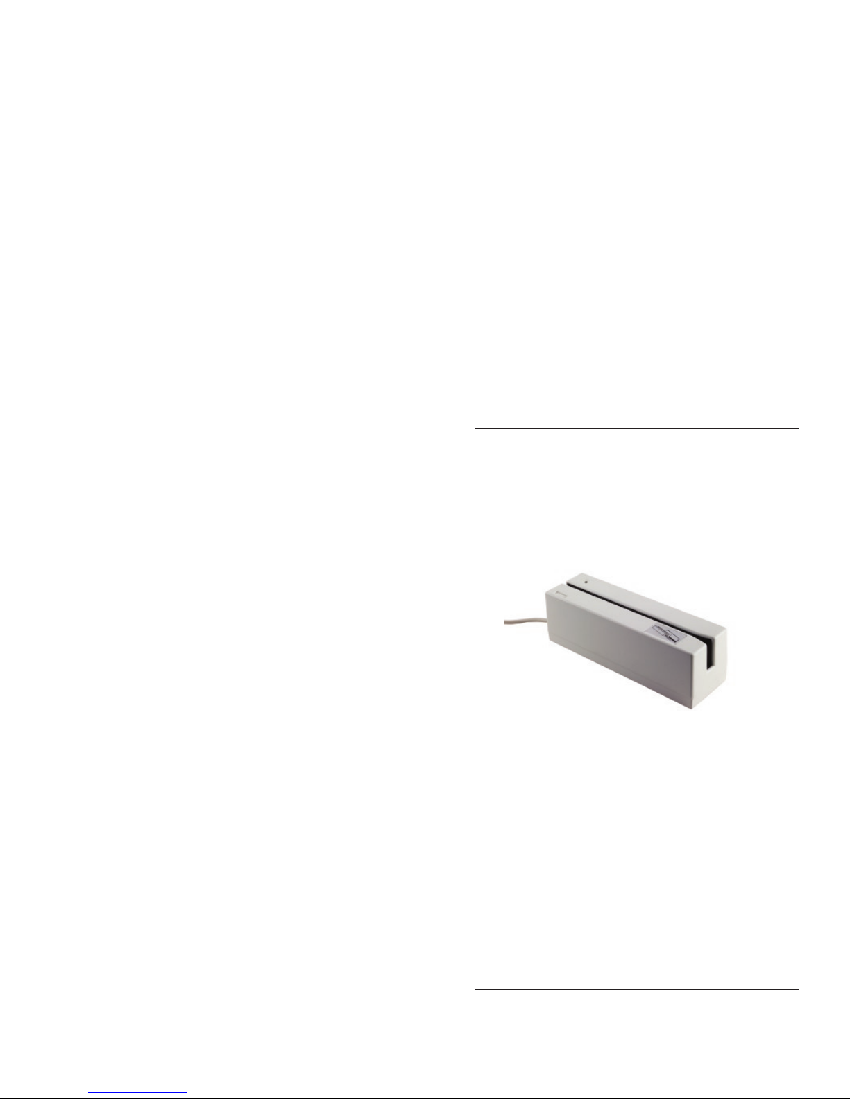
MAINTENANCE
The GM2250 requires card slot cleaning on a regular interval. The interval
is approximate and should be after every 50,000 card swipes. Regular
cleaning insures oils and debris do not accumulate on the operating
components.
Over time, operation can cause a film to collect on the heads and other
surfaces. This film should be removed using “cleaning cards”. These are
available from magnetic stripe cleaning card sources. Cleaning cards are
about the same size as an ID1 (credit card) and have an absorbent surface
on one or both sides. The absorbent surface has an alcohol solvent that
should remove any film. The absorbent surface should be damp; the
surface should not be saturated.
Swipe the card five to ten times with the solvent side of the card toward the
read and write heads and then again five to ten times with the solvent side
opposite the heads.
The cleaning cards may not remove all the debris. In the case of debris
such as dust and card particles in the slot, use an aerosol can product
having clean compressed air. The clean air can be used to blow debris
from the slot. Direct the stream of air at a low angle into the slot and run
the nozzle along the slot. Direct the air in the direction of the card travel
and then in the opposite direction. Inspect the slot by looking down its
length with a good backlight to see if all debris are removed.
The metal housing can be cleaned with a mild detergent applied to a soft
cloth that is rung almost dry. Detergent should not be allowed to enter the
card slot.
Warning: There are no serviceable components inside the GM2250.
Opening the GM2250 voids the warranty. Tampering with the write head
or tachometer assemblies may change the GM2250 calibrations for ISO
standards operation.