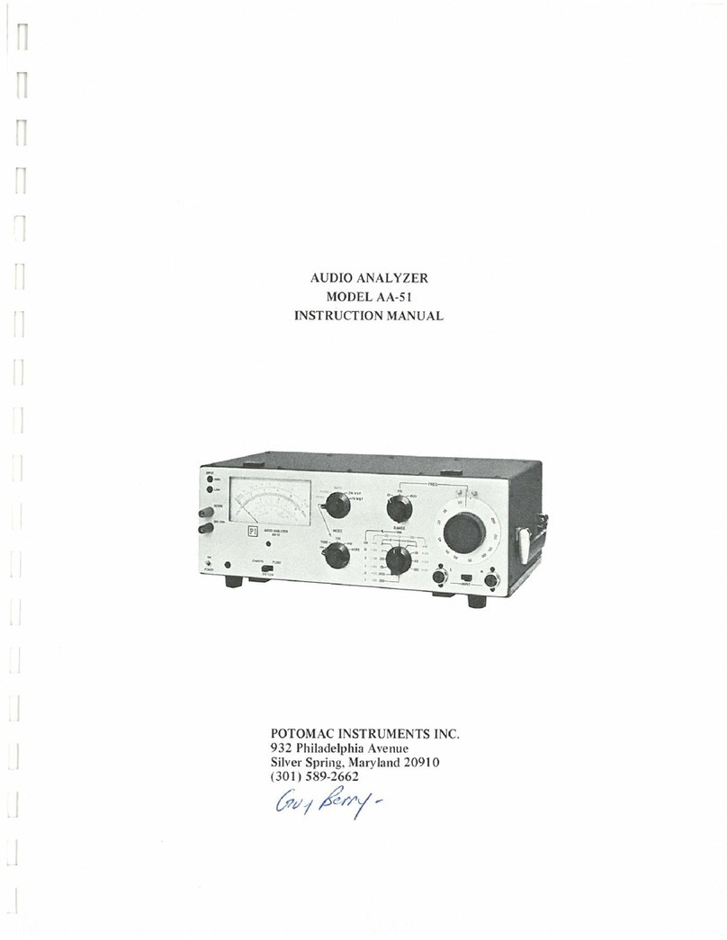
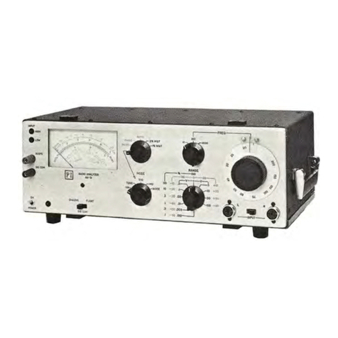
POTOMAC INSTRUMENTS INC. AA-51A User manual

www.SteamPoweredRadio.Com
l~I
Potomac
Instruments,
Inc.
Table
of
Contents
AA-51A
User's Guide
Revised
062800
1 GENERAL DESCRIPTION.......................................................................................................................... 1
1.1 OVERVIEW...........
..
....
..
.
..
...
....
.....
..
..........
......
..
..
..................................................
..
.................................
..
..
..
.. 1
1.2 AA-51AAUDIO
ANALYZER
KEY
FEATURES
.................
..
.....................................................
.. ..
..
..
......
...
..
.
..
.... 2
1.3
SPECIFICATIONS
..
...
..
.........
....
..
..
....
..
...
..............
..
.
..
..............
..
..............
....
...
........................
..
........
..
.
...
..
.......... 3
1.3.1 Inputs
..
.....................
..
...
..
..
...
....
..........
..
.
..
......................
....
........
...
........
..
...
..
........
..
.
..
......
..
.
..
..
..
...........
..
3
1.3.2 AC Voltmeter (VM)...............
...
............
..
.................
..
..
..
....................
......
............................
...
..
........... 3
1.3.3 Total Harmonic Distortion Meter (THD) ...............
...
..
..........................
..
....
..
............
..
....
........
..
.......... 3
1.3.4 Intermodulation Distortion Meter (IMD) ...........
..
.
....
......
..
.
...
.............
..
.
..
...
..
..........
..
...
.......
..
........
..
..... 4
1.3.5 Noise Meter (NOISE)...
..
.....
....
.................
..
.......
..
..
...
..
...
..
..
...
.....
...
.
...
......................
..
.....
..
.....
....
........... 4
1.3
.6
Phase Meter (PHASE)
..
....................
..
.
..
.
..
......
...
.
...
......................
..
.......
..
.....
..
...............
....
................... 4
1.3.7 Ratio Meter (RATIO)
...
..
.
...
................................................
..
................
..
.
...
..............................
..
......... 4
1.3.8 Wow & Flutter Meter (%W&F) .
..
........
..
..
..
.....
....
..
....
.........
...
.............
..
..
..
.....
..
.
..
..
...
..
......
..
.....
..
.......
..
.. 4
1.3.9 Frequency Counter....................................................
..
.
..
..
....
....
..
.................
..
.....
..
.......
...
..
.
..
.
..
.
....
.......
..
5
1.3.10 Auxiliary AC Output................................................................................
..
...........
..
.....
...
..
..............
...
.. 5
1.3.
11
Power
..
......................
..
...........
..
..........
....
..........
..
..
...............
....
...................
...
..
..................................
...
5
1.3.
12
Weight.....
....
...........
...
....
....
.........
...
......
..
.........
...
.
..
.....
..
.
...
..
.................
..
..............
..
............
..
......
..
.......... 5
1.3.13 Dimensions
..
.
..
.......................
..
..
..
....
..
.
...
.
..
.............
....
.......
..
....................
..
..................
..
..
..
.....
..
....
..
...... 5
2 INSTALLATION............................................................................................................................................ 6
2.1
UNPACKING
............................
..
.....
..
...
.
...
.................................................
..
......
..
.
..
..
..
..
............
..
.
..
........
...
....... 6
2.2
RESHIPME
NT
TO
FACTORY
..
.............:..................
..
....
..
...
..
......
...
............
..
.............
..
..............
..
............
..
.....
..
.
..
6
2.3
WARRANTY
FOR
EQUIPMENT
AND
ACCESSORIES
...
.......
...
........
....
.....
...
...
....
...
..
................
..
.....
....
.
..
..
............... 6
3 CONTROLS AND INDICATORS ................................................................................................................ 7
3.1
FRONT
PANEL
.....
...
............................
...
...........
...
...
...
.........
..
..
..........
...
......
..
.....
..
.....
..
...............
..
...........
..
...
.... 7
3.1.1 Power Switch and Indicator
..
..................
..
........
..
.
..
.....
...
.
..
..
..
.......
...
....
..
..............
..
..
......
..
..............
...
.... 7
3.1.2 Input Monitor Headphone Output ...............................
..
............
..
..................
..
.........
...
..................
....
.. 7
3.1.3 Input Monitor Scope Output.....
...
.................
...
................
..
............
..
.......................
..
........
..
.
..
.............. 8
3.1.4 Meter.Monitor Scope Output.....
....
....................
..
...
......
..
..
...................
..
.
..
.............
....
........
..
.......
...
...... 8
3
.1
.5 Input Level LED Indicators ...............
...
.....
...
.....
..
.............
..
.................
..
.
...
..
..
..
...
..
...
..
......
..
...
.
..
....
..
...... 8
3.1.6 Meter and Mechanical Zero...
..
.
..
...............
..
........
..
.....
..
...
.
..
............................................
...
.
..
.
..
......
...
.
..
9
3.1.7 Upper and Lower Mode Select Switches..........
..
.
..
.
..
........
...
.
..
.
..
..................
..
...
.
...
..
..
.
..
.
..
...................
10
3.1.8 Range Select Switch
..
..
..
.....
....
...........
....
..........
..
.
...
.......
....
.
..
.....
......
...................
..
..
..
..
..
..
..
..
.
..
..........
..
..
11
3.1.9 Adjustable Reference Set Control and UNCALLED..................
..
......
....
............................
..
............
11
3.1.10 Digital Frequency Counter...........
....
...
..
................
..
...
..
..
..
.
..
......
..
.......................................................
12
3.1.11 400 Hz HP Filter Select Switch and LED....
...
.........
..
.......
...
..
..
...
......
.
..
..
........
..
..........
..
....
..
.....
..
.
...
.....
12
3.1.12 22 kHz LP Filter LED .................................
...
...............................
.'
...
.
..
............................
..
................
12
3.1.13 Left and Right Signal Inputs and Input Select Switch .
..
....................
...
........
..
...................................
12
3.2
REARPANELCONTROLSANDCONNECTORS
......
..
.....
..
...
..
..
..
..
................
..
..
..
...
..
..................
..
...
..
................
..
13
3.2.1
ACPowerlnput
.
...
......
..
....
..
..
............
..
...............
..
.....
..
........
..
.
..
.......................
..
.
..
......
....
..
..
...........
...
..
13
3.2.2 Auxiliary
AC
Power Output...........................
..
........
..
.........
..
...................
..
...
.........................
...
..
..
...
..
13
3.2.3 Fuse Location
...
.'
...
......:..
.'
:.:
.........
..
...::.:.......
...
..
.'
........::.
:.-
.:...
'.:
.
..
'....
..
............
..
.
..
.
..
.........
..
......................
13
3.2.4 Headphone Gain Control ....................................
..
.
..
....
..
...............
...
...
..
...................
..
..
..
..................
..
14
3.2.5 Identification Plate.....
..
..........................
..
..
.....
..
...
....
..
...........
..
.......
..
..............
..
.........
...... ..
.............
..
..
14
3.2.6 Chassis Ground Terminal ..............
..
............
...
...........................................................
..
.............
....
...
..
14

www.SteamPoweredRadio.Com
~
Potomac
Instruments,
Inc.
AA-51A
User
's
Guide
Revised
062800
3.3
GENERAL
OPERATING
INFORMATION
....
..
.
..
.................................................................................
..
..
....
.........
15
3.3.1 Meter Mechanical Zero...........................................................................................
..
...
......................
15
3.3.2
AC
Power...........................................................................................................................................
15
3.3.3 Grounding..........................................................................................................................................
15
3.3.4 Use
of
METER
MONITOR OUTPUT......
..
..
..................................................................................
..
15
3.3.5 Equipment Performance Measurements............................................................................................
15
3.3.6 NAB Test CDs as Test Signal Sources........
..
....................................................................................
16
4 OPERATION ................................................................................................................................................
17
4.1
VOLTMETERMODE
......................................................................................................................................
17
4.1.1 Absolute Voltage Measurements.......................................................................................................
17
4.1.2 Relative dB Voltage Measurements..............................................................
....
.................................
17
4.2
TOTAL
HARMONIC
DISTORTION
(THD)
MODE
..
.......................................................
...
.
...
..
.
..
..................
..
.
..
18
4.2.1 Measuring Percentage
of
Total Harmonic Distortion........................................................................
18
4.2.2 Measuring THD Level in
dB
below Input Signal .............................................................................. 19
4.2.3 Monitoring THD with an Oscilloscope......................................................
..
......
..............................
..
19
4.3
INTERMODULATION
DISTORTION
MODE
................................
..
...
................................................................
..
19
4.4
NOISE
MODE
..
............
..
..............................
..
..........................
..
...............
..
..
...
.............................................. 20
4.5
PHASE
ANGLE
MODE
...................................................................................
...
........
..
........................
...
....
.
...
21
4.6
RATIO
MODE
................................
···
·······.......................
....
......···························......................................... 22
4.7
WOW
AND
FLUTTER
MODE
.......................................................................
..
.......
..
.......
..
.....
..
.....................
..
. 22
5 FACTORY CONTACT INFORMATION................
..
............................................................................... 24
APPENDIX
A.
RETURN MATERIAL AUTHORIZATION FORM............................................................. 25
List
of
Figures
Figure
1.
AA-51A Front Panel Controls, Connectors, and Indicators......
..
.................................................?
Figure
2.
Monitor Outputs Connectors and Level Indicators ............................................
..
....
....
...
..........
...
8
Figure
3.
Meter Face Close-up View............................................................................................................9
Figure
4.
Mode Select Switch Close-up View.............
...
...........................................................................
10
Figure
5.
Range Select Switch Close-up View
..
...................................
..
............................................
..
.....
11
Figure
6.
Adjustable Reference Set Control and
UN
CAL LED Close-up View.......................................
11
Figure
7.
Frequency Counter Close-up View.............................................................................................
12
Figure
8.
Left and Right Signal Inputs and Input Select Switch Close-up View......................................
12
Figure 9. AA-51A Rear Panel Connectors and Controls ..................
..
.......................................................
13
11

www.SteamPoweredRadio.Com
~
Potomac
Instruments,
Inc.
AA-51A
User's Guide
Revised
062800
'.
;:
..
1 General Description
1.1
Overview
The AA-5
lA
is a multi-purpose, precision audio analyzer, that helps to automate broadcast station proof-
of-performance measurements and equipment maintenance.
It
is designed to work efficiently with the
companion AG-51 Audio Generator, especially for Intermodulation Distortion, Total Harmonic Distortion,
and stereo broadcast system measurements. Having the generator and analyzer in two separate assemblies
allows local measurements, as well as complete measurement capabiltities through one-way links, such as
from a studio to a remote transmitter. The AA-51A analyzer measures:
1
■
Audio Voltage. The AA-SIA voltmeter can be used for general purpose voltage, gain, and
frequency response measurements. The meter is calibrated in voltage, dB, and dBm referenced to
600 Ohms.
It
has a flat frequency response (±0.1 dB) range
of
20
Hz
to 200 kHz, and eleven full-
scale voltage ranges from 0.3
mV
(-68 dBm) to 30 V (+32 dBm). The average responding meter is
calibrated to the rms value
of
a sinewave.
■
Total Harmonic Distortion (THD). Total harmonic distortion levels are automatically measured
in six full-scale ranges
of0.03%
to 10% for any fundamental frequencyfrom 20 Hz to 20 kHz.
Harmonics to·100 kHz are measured.
It
automatically accomplishes nulling, tuning, and leveling to
the input frequency for signals between 0.1 and 80 Vrms.
■
Intermodulation Distortion (IMD). Intermodulation distortion levels are automatically measured
in six full-scale ranges
of
0.03% to 10% in accordance with the SMPTE Standard, using a 60
Hz
and a 7 kHz signal in a
4:
1 voltage ratio. Measurements are completely automatic over a wide
dynamic range. A high precision IMO signal, with the SMPTE characteristics, is available directly
from the companion AG-51 Audio Generator.
■
[Signal+
Noise]/
[Noise]. Noise levels as low as -85 dBm (600 Ohms) can be measured. The
noise measuring function is essentially the same as the audio voltmeter function described above,
except that the operating passband is restricted to a 3 dB bandwidth
of
20 Hzto 20 kHz.
■
Stereo Phase. The relative phase angle between two signals is measured in two ranges
of
±54
degrees and ±180 degrees, within a frequency range
of
20 Hz to 20 kHz. Phase angle is displayed
with a zero-center scale indication. The companion AG-51 Audio Generator provides precision 0
degree (L+R) and 180 degree (L-R) test signals.
■
Stereo Ratio. The amplitude ratio
of
two signals is measured over a range
of
±6 dB within the
frequency range
of
20 Hz to 20 kHz. The ratio meter indication is a zero-center scale with ±6 dB
full-scale deflection.
■
Wow and Flutter. Incidental frequency modulation ("Wow and Flutter") usually associated with
tape decks, cartridge machines, and turntables is measured automatically in two full-scale ranges
of
0.
3%
and
0.1
%.
The AA-5
lA
measures weighted peak flutter as specified by IEEE Standard 193
using a 3.
15
kHz(±
10%) at a level between
0.1
Vrms and 80 Vrms. The companion AG-51 Audio
Generator provides a highly stable 3.15 kHz test signal.
■
Frequency. The
AA-SIA
includes a fast response four-digit LED display
of
input frequency. The
decimal point and Hz/kHz indicators shift automatically to maintain optimum resolution. The
counter functions in all AA-51A operating modes.
1
www.SteamPoweredRadio.Com
~
Potomac
Instruments,
Inc.
1.2 AA-51A Audio Analyzer Key Features
■
Auto-Null Total Harmonic Distortion Measurement
AA-51A
User's Guide
Revised
062800
■
Switch selectable 400 Hz high pass input filter to reduce line frequency noise
■
Switch selectable 22 kHz low pass filter to allow THD measurement ofdigital signal sources
■
Oscilloscope
and
headphone monitor outputs
■
LED indicators for out-of-range input levels
■
Uncalibrated meter adjustment mode for easy relative measurements
■
Digital frequency readout
■
Compatibility with NAB Test CD's*
■
Shielded and balanced inputs
■
Extensive
RFI
shielding for operation in high power transmitter signal environments
■
Rugged protective carrying case with handle
■
Auxiliary AC power outlet on
rear
panel for powering companion test equipment
*See Section 3.3.6 on page
16
for information regarding NAB Compact Discs
2

www.SteamPoweredRadio.Com
~
Potomac
Instruments,
Inc.
1.3 Specifications
1.3.1
. Inputs
Impedance
Maximum AC
Maximum
DC
Common-mode rejection
Cable connector
MON
SCOPE output
MON
PHONES output
HIGH LED on when
LOWLED on when
1.3.2
AC
Voltmeter (VM)
Frequency response
Ranges
Accuracy
METER
MON
output
Internal noise
Filter
REF SET Range
AA-51A
User
's Guide
Revised
062800
Balanced 80 k Ohms, plus 100 pF, each pin to ground
220
Vnns
,
each
pin
to
ground
250 Vde, each pin to ground
greater than 60dB
Switchcraft p/n 05CL3M
5.6 V pk-pk for inputs from 40 mVrms to 90 Vrms, typical
Adjustable to 70 mVrms with rear panel control.
Input greater than 80 Vrms (not active in
VM
and NOISE modes)
Input less than 100 mVrms, (not active in
VM
and NOISE
modes)
10 Hz to 100 kHz, ±0
.1
dB max. variation
11
ranges, 0.3
mV
to
30
V full scale, -68 dBm to +32 dBm full
scale
±3%
100 mV pk-pk, meter at full scale
20
uV
(-92 dBm) maximum
400 Hz (at
-3
dB) high-pass, switch selected
greater than 10 dB
1.3.3 Total Harmonic Distortion Meter (THO)
Input frequency range
Measurement passband
Notch attenuation
Ranges
Accuracy
Input level range
Internal THD + noise
Filters
METER
MON
output
Nulling time
20
Hz to
20
kHz, fundamental
1.7x to 12.5x input frequency at -3dB
greater than 100 dB
6 ranges, 0.03%
to
10% full scale,
-20 dB to -70 dB full scale
±15% (±1.5 dB)
100
mV
to 80 Vrms
0.
01
% max, 0.006% typical, 20 Hz-5 kHz
0.02% max, 0.012% typical at 20
kHz
22
kHz low-pass at input, switch selected
400 Hz high-pass, switch selected
100 mV pk-pk, meter at full scale
2 seconds approximately
3

www.SteamPoweredRadio.Com
~
Potomac
Instruments,
Inc.
1.3.4 Intermodulation Distortion Meter (IMO)
Input signal required
Full scale ranges
Accuracy
Input level range
Internal
IMD
+noise
METER
MON
output
60
Hz+
7 kHz, 4:1 voltage ratio
6 ranges, 0.03% to 10% full scale
±10%
100
mV
to 80 Vrms
less than 0.015%
100
mV
pk-pk, meter at full scale
1.3.5 Noise Meter (NOISE)
Frequency response
Ranges
Accuracy
METER
MON
output
Internal noise
Filter
REF SET range
20 Hz to 20 kHz
at
-3
dB
11
ranges, 0.3 mV to
30
V full scale
±3%
100 mV pk-pk, meter
at
full scale
15
uV (-94 dBm) max.
400
Hz
(at
-3
dB) high-pass, switch selected
greater than 10 dB
1.3.6 Phase Meter (PHASE)
Measurement ranges
x3
xlO
Accuracy
Polarity
±54 degrees full-scale
±180 degrees full-scale
±3 degrees
Positive angle means Left leads Right input
20 Hz to 20 kHz
100
mVto
80 Vrms
AA-51A
User's Guide
Revised
062800
Input frequency range
Input level range
METER
MON
output The input signal is converted to a rectangular wave
at
the input
frequency. The duty cycle
of
the rectangular signal is
proportional to the phase angle.
1.3.7 Ratio Meter (RATIO)
Measurement range
Accuracy
Polarity
Input frequency range
Input level range
METER
MON
output
±6dB
±0.2 dB
Positive ratio means R greater than L
20 Hz to 20 kHz
100
mV
to 80 Vrms
DC voltage proportional to ratio
1.3.8
Wow
& Flutter Meter (%W&F)
Measurement ranges
Input frequency
Accuracy
Input level range
Internal noise
METER
MON
output
0.1% and 0.
3%
full scale
3.15 kHz, ±10%
±10%
100 rnV to 80 Vrms
less than 0.01%
500 rnV pk-pk at full scale, passband0.2
Hz-
200 Hz
4

www.SteamPoweredRadio.Com
~
Potomac
Instruments,
Inc.
1.3.9 Frequency Counter
Frequency range
10
Hz
to
200
kHz
Resolution less than 900 Hz (approx.),
0.1
Hz
900 Hz to 9000
Hz
(approx.), 1.0
Hz
Accuracy
Input level range
9 kHz to 24
kHz
(approx.), 0.01 kHz
greater than 24
kHz
(approx.), 0.1
kHz
-1
to Ocount error in
RH
digit (LSD)
1
mVto
80V
1.3.10 Auxiliary
AC
Output
Current 4.0 Amperes rms, maximum
1.3.11 Power
Voltage
Power Consumption
1.3.12 Weight
Pounds
Kilograms
1.3.13 Dimensions
Inches (W x H x D)
CM(WxHxD)
Optional Rack Mount
117 VAC (230 VAC option), 50/60
Hz
10
Watts
12
5.44
15.25 X 5.25 X 10.125
38.74 X 13.34 X 25.72
3-ru required (5.25 inches, or 13.34 cm)
Specifications subject to change without notice.
5
AA-51A
User's Guide
Revised
062800

www.SteamPoweredRadio.Com
~
Potomac
Instruments,
Inc.
2 Installation
2.1
Unpacking
AA-51A
User's Guide
Revised
062800
The AA-5
lA
is packed in a custom shipping carton. Inspect the carton for any signs
of
serious damage.
Report any damage to the shipping company.
Carefully remove the AA-5
lA
from the shipping carton. A technical manual and power cord are also
included in the carton.
It
is recommended that the carton and packing materials be stored in case that the
unit must be shipped.
The AA-51A is ready for operation as delivered.
It
only requires an AC power source. To operate the
unit, remove the front protective cover which
is is
held on with four snap-release holders.
WARNING
The AA-51A must be used with a 3-prong grounded receptacle outlet. Failure to use
a grounded outlet may result in improper operation or a safety hazard.
2.2 Reshipment to Factory
If
at all possible, the unit should be shipped in its original carton
if
it must be returned to the factory.
Shipping cartons can be ordered from the factory
if
other suitable packaging is not readily available.
Contact information can be found in Section 5 on page 24
of
this manual.
If
the AA-SIA fails to perform properly, initially or after a period
of
use, it is advisable to contact a factory
technician. Ifrepair is required, an
RMA
number must first be obtained from the factory. For returned
units that are not under warranty, repair cost estimates will be provided. Authorization to proceed must be
obtained from the customer before repairs will be completed.
If
return to the factory is not possible,
Potomac Instruments can supply technical data and parts. Please contact the factory for a cost estimate.
!Not~
A Return Material Authorization (RMA) number must be obtained prior to returning a unit to the
factory. A copy
of
a Return Material Authorization form is included as Appendix A to this manual. Please
call, fax, or e-mail the factory to obtain an RMA number. Please also fax a copy
of
the RMA to the factory
and include a copy
of
the RMA in the carton with the unit. Contact information can be found in Section 5
on page 24
of
this manual.
2.3 Warranty for Equipment and Accessories
Potomac Instruments, Inc., warrants each new equipment to be free
of
defects in material and
workmanship, for a period
of
one (1) year after the date
of
original shipment, except for fuses, transistors,
diodes, and integrated circuits, which are warranted for a period
of
ninety (90) days. Any instrument
which is found within one year not to meet the foregoing standards after examination by our factory, will
be repaired, or at the option
of
Potomac Instruments, replaced without charge. This warranty does not
apply to equipment which has been altered, improperly handled, or damaged in any way.
6

www.SteamPoweredRadio.Com
l~I
Potomac
Instruments,
Inc.
AA-51A
User's Guide
Revised
062800
3 Controls and Indicators
3.1
Front Panel
Refer to Figure 1 for the following discussion. The numbers shown in parentheses ( ) are used as
identifiers in the discussion below.
(5)
Meter
Monitor
Scope
Out
(3)
Input
Monitor
Headphone
Out
(6)
Input
Level
LED
Power
(7)
Meter
Indicator
High
Pass
Filter
Mechanical
Zero
(10)
Reference
Set
Uncal
LED
Input
Figure
1.
AA-51A Front Panel Controls, Connectors, and Indicators
3.1.1 Power Switch and Indicator
(11)
Digital
Frequency
Counter
Display
(14)
Carrying
Handle
(15)
Right
Input
The
AC
Power
Switch
(2)
is
located
in
the
lower
left
corner
of
the
front
panel.
Placing
the
toggle
switch in the upper position applies power to the unit. An LED Power Indicator
(1
),
just
to the
right
of
the switch, will be illuminated when the unit is operating.
3.1.2 Input Monitor Headphone Output
The Input Monitor Headphone Output (3) permits listening to the signal that is applied to the
selected input connector before it passes through any filters or nulling circuitry. A headphone
gain control
is
located on the rear panel to adjust the level at the headphones. High or low
impedance headphones with a standard "tip-sleeve" or "tip-ring-sleeve" headphone plug can be
used. Figure 2, on page
8,
shows a close-up
of
the connector and markings.
7

www.SteamPoweredRadio.Com
~
Potomac
Instruments,
Inc.
3.1.3 Input Monitor Scope Output
AA-51A
User's Guide
Revised
062800
The Input Monitor Scope Output (4) permits oscilloscope monitoring
of
the signal that is applied
to the selected input connector before it passes through any filters or nulling circuitry. A BNC
connector is used. Figure 2 shows a close-up
of
the connector and markings.
3.1.4 Meter Monitor Scope Output
The Meter Monitor Scope Output (5) permits monitoring the signal that drives the meter. The
signal at this output will have passed through any selected filters or nulling circuitry. A BNC
connector is used. Figure 2 shows a close-up
of
the connector and markings.
3.1.5 Input Level LED Indicators
A pair
oflnput
Level LED Indicators (6), marked HIGH and LOW, alert the operator to signal
levels that are out
ofrange
to make accurate measurements. The LOW LED will be on
if
the input
is less than 100 mVrms. The HIGH LED will be on
if
the input is greater than 80 Vrms. The
LED's are not active in the VOLTMETER and NOISE modes. Figure 2 shows a close-up
of
the
indicators.
Figure 2. Monitor Outputs Connectors and Level Indicators
8

www.SteamPoweredRadio.Com
~
Potomac
Instruments,
Inc.
3.1.6 Meter and Mechanical Zero
AA-51A
User's
Guide
Revised
062800
The Meter (7) has five scales. The uppermost scale is calibrated in dBm referenced to 600 ohms.
It
corresponds to the green markings associated with the Range Select Switch. The two middle
scales are linearly calibrated for measuring voltage and percentages
of
distortion. They
correspond to the black markings associated with the Range Select Switch for Volts, mV, and %
of
distortion, and with the Upper Mode Switch for percent
of
Wow and Flutter. The bottom two
scales are used with the
Upper
Mode Switch for RATIO and PHASE measurements. When used
in the RATIO mode, the upper scale is used directly in dB. When in the PHASE mode the lower
scale corresponds to the PHASE x3 Mode for readings up to ±54 degrees (±15 equals ±45
degrees). In the PHASE
xl0
Mode the lower scale corresponds for readings up to ±180 degrees
(±
15
equals ±150 degrees).
The meter's Mechanical Zero (20) adjustment is accessible through a hole in the front panel
just
below the meter face. Before operating the AA-5
lA
for the first time, check the meter mechanical
zero. To do this,
if
the analyzer is on,
tum
it off, and allow 2 to 3 minutes for complete capacitor
discharge.
Tum
the meter zero adjust screw, shown below, using a small-bladed screwdriver
until an exact zero indication is achieved.
Figure 3 shows a close-up
of
the meter face and the mechanical zero adjustment.
Figure 3. Meter Face Close-up View
9

www.SteamPoweredRadio.Com
~
Potomac
Instruments,
Inc.
3.1.7 Upper and Lower Mode Select Switches
Refer to Figure 4 for the following discussion.
AA-51A
User's Guide
Revised
062800
The Upper Mode Select Switch (8) is used to select the PHASE
x3,
PHASE
xlO,
RATIO,
0.1
% W&F (Wow and Flutter), and the 0.3% W&F. In its most counter-clockwise position the
switch transfers control to the Lower Mode Select Switch.
The Lower Mode Select Switch (9) is used to select the VM (Voltmeter), THD 22
kHz
(Total
Harmonic Distortion below 22
kHz),
THD (Total Harmonic Distortion), IMD (Intermodulation
Distortion), and the NOISE functions. The Upper Mode Select switch must be in its most
counter-clockwise position for this switch to be functional.
Figure
4.
Mode
Select
Switch
Close-up
View

www.SteamPoweredRadio.Com
~
Potomac
Instruments,
Inc.
3.1.8 Range Select Switch
AA-51A
User's Guide
Revised 062800
The Range Select Switch (18) is used to select the full scale range in Volts, dB, and Percentage.
The black innermost markings are associated with the Meter's center black ranges. They range
from full-scale readings
of
0.3 milliVolts rms (mVrms) to 30 Volts rms (Vrms). They are used
with the Voltmeter (VM) and NOISE measurement modes.
The next set
of
markings, in green, is associated with the Meter's uppermost scale, which is also
green. The scales range -70 dB to +30
dB.
The readings are direct in dBm when measuring 600
Ohm sources (0
dBm=
1 mW across 600 Ohms). These scales are also used with the Voltmeter
(VM) and NOISE measurement modes.
The left-most black markings are in PERCENT, and they too are associated with the Meter's
center black ranges. They range from full-scale readings
of
0.03% to 10% and are used in
conjunction with the Total Harmonic Distortion (THD) and the Intermodulation Distortion (IMD)
measurement modes. Readings above the 10% marking are essentially non-functional and
irrelevant.
Figure 5. Range Select Switch Close-up View
3.1.9 Adjustable Reference Set Control and UNCAL LED
The Adjustable Reference Set Control (9) allows uncalibrated meter readings, such as for making
relative power measurements. The meter readings are calibrated when this control is in its most
clockwise and locked position. Turning the control counter-clockwise provides up to
10
dB
of
continuously variable meter adjustment range. When the control is in the unlocked, or
uncalibrated position, the
UNCALLED
(10) will be illuminated. Refer to Section 4.2.2 on page
19 for an explanation
of
the THD dB function. Figure 6 shows a close-up
of
the control and LED.
Figure 6. Adjustable Reference Set Control and UNCAL LED Close-up View
11

www.SteamPoweredRadio.Com
~
Potomac
Instruments,
Inc.
3.1.10 Digital Frequency Counter
AA-51A
User's Guide
Revised
062800
A four-digit LED Frequency Counter Display (11) indicates the frequency
of
the input signal. The
frequency counter is auto ranging, i.e., it automatically sets the decimal point, and an additional
indicator shows whether it is measuring Hz or kHz. Figure 7 shows a close-up view
of
the display.
Figure
7.
Frequency Counter Close-up View
3.1.11 400 Hz HP Filter Select Switch and LED
The 400 HzHP (21) filter select switch is located below the meter. The Input signal passes
through a 400 HzHigh Pass filter when this switch is in the
"IN"
position. The 400 Hz HP LED
(12), located below the Frequency Counter display, lights when the filter is selected.
3.1.12 22 kHz LP Filter LED
The 22,kHz LP Filter LED (13) lights when the TI-ID 22 kHz LP mode is selected with the Lower
Mode Switch. The LED is located below the Frequency Counter display.
3.1.13 Left and Right Signal Inputs and Input Select Switch
The Left (17) and Right (18) Signal inputs are located in the lower right comer
of
the front panel.
They are used to apply signals to the analyzer for measurement. The PHASE and RATIO modes
use both connectors simultaneously. The other modes use one or the other input, as selected by
the Input Select Switch. The mating connectors are Switchcraft Part Number O5CL3M, available
from Switchcraft distributors or from Potomac Instruments.
Figure 8. Left and Right Signal Inputs and Input Select Switch Close-up View
12

www.SteamPoweredRadio.Com
f!l!I
Potomac
Instruments,
Inc.
3.2
Rear Panel Controls and Connectors
Please refer to Figure 9 for the following discussion.
(24)
Headphone
Gain
Control
(23)
Auxiliary
AC
Power
Output
(25)
Identification
Plate
AA-51A
User's
Guide
'
Revised
062800
(26)
Chassis
Ground
(27)
Line
Fuse
Figure 9. AA-51A Rear Panel Connectors and Controls
3.2.1
AC
Power Input
A power cable with a standard IEC-type power connector provides AC Power Input (22)to the
AA-SIA
The units are available from the factory for either 115 or 230 VAC operation. The
voltage requirements are listed on the Identification Plate described below.
3.2.2 Auxiliary
AC
Power Output
A North American style three-prong Auxiliary AC Power Output (23) connector provides an
unfused AC outlet to power companion equipment such as the AG-51 Audio Generator or an
oscilloscope. The maximum current which can be safely drawn from this connector
is
4.0
Amperes rms.
3.2.3 Fuse Location
The AC Line Fuse (27) is accessible in a screw-type holder on the rear panel. A 3/16 ampere, 250
VAC slow-blow fuse is installed for units configured for 115 VAC operation. A 1/8 ampere, 250
VAC slow blow fuse
is
installed in units configured for 230 VAC operation. The operating
voltage and fuse value is listed on the Identification Plate described below.
13

www.SteamPoweredRadio.Com
I~
Potomac
Instruments,
Inc.
3.2.4 Headphone Gain Control
AA-51A
User's Guide
Revised
062800
The level
of
the front panel Input Monitor Headphone Output is controlled by the Headphone
Gain Control (24) located on the rear panel.
3.2.5 Identification Plate
The Identification Plate (25) shows the model number, serial number, AC Voltage requirements,
and the fuse size and type.
3.2.6 Chassis Ground Terminal
A three-way Chassis Ground Terminal (26) is located on the rear panel to provide additional
protection and grounding options
if
the AC power source does not provide an adequate earth
ground. Refer to section 3.3.2 for additional information.
14

www.SteamPoweredRadio.Com
(iii)
Potomac
Instruments,
Inc.
3.3 General Operating Information
3.3.1
Meter Mechanical Zero
AA-51A
Use'r's Guide
Revised
062800
Refer to Section
3,
1,6 on page
19
for instructions on setting the Meter Mechanical Zero
if
the
Meter does not read exactly zero when the unit is level and powered
off
3.3.2
AC
Power
The AA-51A Audio Analyzer should be operated from a 115 or
230
volt AC power source
according to the rating on the Identification plate located on the rear paneL
3.3.3 Grounding
When the AA-51A power cord is plugged in, the chassis is connected directly to the AC power
neutral line through the third wire
of
the power cord, This may or may not provide minimum
pickup
of
unwanted hum and noise in the measuring circuits, Often the AA-51A must be
grounded solidly to the equipment under test to obtain minimum hum pickup, This connection
may be made using the test cable shield, which is connected to the chassis, or by a separate wire
from the ground binding post on the rear
of
the
unit
In such cases, it may also be necessary to
isolate chassis ground from power line ground, using a three-prong-to-two-prong adapter to obtain
minimum noise pickup, Ifthis
is
done, be certain to observe the following warning:
WARNING
Be certain that the chassis
of
the AA-51 is solidly grounded to an earth-grounded point
before using the
unit
Dangerous voltage may be present on the AA-51A chassis
if
it is
not adequately grounded, A separate ground connector is located on the rear panel, as
described below,
3.3.4 Use of METER MONITOR OUTPUT
The METERMONITOR OUTPUT connector provides a 100 mV pk-to-pk output for full-scale
meter deflection. The output is designed to monitor the meter signal with an oscilloscope, The
combination
of
the analyzer and oscilloscope provides more significant information about the
device under test than is expressed in a meter reading alone. The METER MONITOR output
impedance is 2200 Ohms, and excessive loading should be avoided to maintain the accuracy
of
meter readings. High impedance oscilloscope inputs should have negligible effects on the
readings, Refer to sections
3,
l,3 and 3
.1.
4 for more information about the Oscilloscope outputs.
3.3.5 Equipment Performance Measurements
Equipment
Performance
Measurements
(EPM),
used
to
determine
a
broadcast
facility's
audio
performance, are required by the Federal Communications Commission (FCC), and are described
in various sections
of
the FCC Rules, Part 73. These tests are commonly referred to as an "Audio
Proof' although the FCOprefers to use the term
"Proof1
l·on1yfor measurements to verify the
performance
of
AM
directional antenna systems, Useful guides to these EPMs for
AM
and
FM
stations have been prepared by Broadcast Engineering Magazine, and are available from
Broadcast Engineering, P.O. Box 12901, Overland Park, Kansas, 66212.
15

www.SteamPoweredRadio.Com
~
Potomac
Instruments,
Inc.
3.3.6
NAB
Test CDs as Test Signal Sources
AA-51A
User's Guide
Revised
062800
The
NAB
(National Association
of
Broadcasters) has issued Compact Discs (CDs) containing test
signals. The
CDs
are designated "Broadcast and Audio System Test
CD
, Volume I and Volume
II."
Some
of
the signals
on
the
CDs
which are particularly useful with the AA-5
lA
are listed
below:
• Fast full-band THD Test.
Vol.
II
,
Track
28
, has 12 frequencies,
32Hz
to 16kHz, each
on
for 10 seconds. This provides adequate time for the AA-SIA to give a
THD
reading at each
frequency.
• Full-band THD and Frequency Response Test.
Vol.
I~
Tracks 14 through 29, gives 16
frequencies,
20
Hz
to
20
kHz, each
on
for 30 seconds.
• THD Calibration.
Vol.
I,
Tracks 76,77,78, and
79
have 400
Hz
tones with 800
Hz
second
harmonics of0.1%, 0.3%,
1%,
and
3%
, each
on
for 30 seconds. The
0.1%
THD signal gives a
noticeably distorted second harmonic because
of
the limitations
of
digital sampling.
Distortion is less
as
the percent
of
THD
increases.
■
IMD
Test Signal.
Vol.
I,
Track 30, provides an IMD test signal with 60
Hz
and 7 kHz
signals with amplitude ratios
of
4:1
and 1
:
1.
The residual distortion is somewhat high
because
of
the limitations
of
digital sampling.
• Wow and Flutter Test.
Vol. I, Track 72, provides a 3.15
kHz
test signal, on for 30 seconds.
■
Wow and Flutter Calibration.
Vol.
II,
Tracks 14
and
15,
on
for 30 seconds each, have test
signals for calibrating a DIN/IEEE flutter meter with peak flutter values
of
0.1%
and
0.3%
sinusoidal flutter.
The
NAB
CDs
are available from the
NAB
Bookstore, 1771 N Street, N. W., Washington, D. C.
20036, phone (202) 429-5300.
16

www.SteamPoweredRadio.Com
IPII
Potomac
Instruments,
Inc.
4
4.1
Voltmeter Mode
Operation
AA-51A
User's Guide ·
Revised 062800
The AA-51A becomes
a
general purpose AC voltmeter
when
the
Lower Mode Select Switch
is set to the
VM
position.
NOTE
The
Upper Mode Selector Switch
must be
in
its most counter-
clockwise position to for the
Lower Mode Select Switch
to be
operational. Refer to Figure 4
on
page
10
for a close-up photo
of
the
Upper
and Lower
Mode
Select switches.
4.1.1
Absolute Voltage Measurements
NOTE
Absolute Voltage Measurements provide readings
of
the actual voltage.
The readings may be
in
Volts, milliVolts (mV) or in dBm referenced to
600
Ohms. The measurements are designed to display the rms voltage
value
of
a sine wave.
a. Position the
Range Select Switch
to a range exceeding the value
of
the signal to be measured.
b. Connect a signal to either the
L
or
R Connector
with the
Input Select Switch
in the
appropriate position.
c.
Set the
Range Select Switch
to give a meter reading as close to full-scale as possible.
d. Observe the
Meter
indication and meterRange setting to obtain the signal level. The meter's
green uppermost scale is calibrated in
dBm
referenced to
600
ohms. It corresponds to
the
green markings associated with the
Range Select Switch.
The two middle scales are linearly
calibrated for measuring voltage. They correspond to the black markings associated with the
Range Select Switch
for
Volts, mV.
A close-up view
of
the meter is available on page 9.
4.1.2 Relative
dB
Voltage Measurements
NOTE
Relative dB voltage measurements are useful for performing
frequency response or amplitude gain characteristics. Steps for
performing relative measurements are listed directly below.
a.
Follow steps A
through
C directly-above, at-the desir
ed
reference frequency, such as 1 kHz.
b.
Adjust the
Reference Set
control so that the needle is at a convenient reference point, such as
0 dB,
on
the
Meter.
The difference in
dB
above or below the reference reading can
now
be
read directly on the dB scale.
17
Table of contents
Other POTOMAC INSTRUMENTS INC. Measuring Instrument manuals

POTOMAC INSTRUMENTS INC.
POTOMAC INSTRUMENTS INC. AM-19 User manual

POTOMAC INSTRUMENTS INC.
POTOMAC INSTRUMENTS INC. FIM-41 User manual

POTOMAC INSTRUMENTS INC.
POTOMAC INSTRUMENTS INC. AA-51 User manual

POTOMAC INSTRUMENTS INC.
POTOMAC INSTRUMENTS INC. AA-51 User manual

POTOMAC INSTRUMENTS INC.
POTOMAC INSTRUMENTS INC. FIM-21 User manual

POTOMAC INSTRUMENTS INC.
POTOMAC INSTRUMENTS INC. PI 4100 User manual