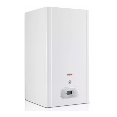
manuals.online logo
Brands
  1. Home
  2. •
  3. Brands
  4. •
  5. Potterton
  6. •
  7. Boiler
  8. •
  9. Potterton Lynx Electronic User manual

Potterton Lynx Electronic User manual

POTT RTON
wall hung gas combination
boiler
THIS APPLIANCE IS FOR USE ON NATURAL GAS
ONLY.
IT IS THE LAW THAT ALL GAS APPLIANCES ARE
INSTALLED BY A COMPETENT PERSON, IN
ACCORDANCE WITH THE GAS SAFETY INSTALLA-
TION AND USE REGULATIONS 1984.
INTRODUCTION
The information given in this booklet will help you to
obtain the maximum comfort from your appliance with
minimum trouble and cost.
Your appliance has been designed to provide central
heating and domestic hot water directly from one unit.
The domestic hot water is produced instantaneously in
a special heat exchanger within the appliance (depend-
ing on the design layout of the DHW a delay may be
experienced on first turning on the tap).The electronic
control circuits havebeendesigned uniquely so that the
temperatures of both the central heating and hot water
can be controlled to provide economic and safe use.
The burner automatically modulates its heat input to
meet the demand of your central heating or hot water.
ELECTRICITY SUPPLY
WARNING: THIS APPLIANCE MUST BE EARTHED.
Connection shall be made to a 240 Volts 50 Hz '
supply. If a mains plug connection is used it must be of
a three-pin type and fused to 3 Amps.
To connect a plug (Fig. 1)
GREEN/YELLOW
EARTH
As the colour of the wires in the mains lead of the
appliance may not correspond with the coloured
markings identifying the terminals in your plug, proceed
as follows:-
The wire which is coloured green-and-yellow must be
connected to the terminal in the plug which is marked
with the letter E or by the earth symbol
-::E-
or coloured
green or green-and-yellow.
The wire which is coloured blue must be connected to
the terminal which is marked with the letter N or
coloured black.
The wire which iscoloured brown must beconnected to
the terminal which is marked with the letter L or
coloured red.
The boiler should have the minimum clearances for
safety and maintenance as shown in Fig. 2. If the
appliance is installed in a compartment do not obstruct
any purpose-made ventilation opening, or usethe com-
partment for storage purposes, e.g.for foodetc.
I
I
I
I
~
MIN 450mm
FROM FRONT OF
BOilER
POTT RTON
user s
guide··
3735
Thesecomprise of:-
1. The boiler ON/OFF switch controls the operation
of the appliance.
2.The summer/winter switch allows the isolation of
the central heating during the summer months.
The appliance has been designed to operate auto-
matically with the minimum of attention by the user.
The only user operator controls on the appliance are
found on the control panel (see Fig. 3).
D.H.W. AND C.H.
TEMPERATURE
INDICATOR
HIGH/LOW
FLAME
LIGHTS
Tltmper tur
H.W.C.H.
Q •••••.
Q
I I
I I
I
I I
•
•
: :
() ftlill •
..Q
CENTRAL HEATING
SUMMER/WINTER
SWITCH
CONTROLS
SEQUENCE
INDICATOR
a) Central Heating Control
The right hand control knob enables you to vary the
temperature of the water as it flows from the appliance.
The knob can be set between Min.and Max. The
graduation Min. to Max.correspond approximately to a
temperature of 60°C to 85°C (140°Fto 185°F).
b) Hot Water
1. Check that the boiler on/off switch is OFFand the
summer/winter switch is set to winter.
2. Ensurethat any time controls are in an ON condition
and any room thermostat is calling for heat.
3.Switch the boiler on/off switch to ON.
The appliancewill now operatein accordancewith pre-
selected temperature demand set on the right hand
temperature control knob.
The left-hand control knob enablesyou to control the
max. temperature of the domestic hot water as it leaves
the appliance. The knob can be set between Min. and
Max.The graduation Min. to Max.corresponds
approximately to a temperature of 35
Q
C to 65°C (95°F
to 149°F).
The firing of the applianceis fully automatic.
1. Ensurethat the boiler on/off switch on the front of
the appliance is 'ON'.
A clock may have beenfitted in your system, together
with a room thermostat or individual Thermostatic
radiator valves.Full instructions for use of these
controls should be supplied with them. 2. Operation of any of the hot water draw-off points
will operate the appliance.
Note: The maximum water flow temperature is con-
trolled by the left hand temperature control knob.
3 7
35
The indicator lights will operate in the following order.
1. Demand light on.
2. Service indicator light on.
3.Ignition light illuminated only during ignition.
4.Temperature indicator lights show increasing water
temperature.
5. High/Iow flame lights indicate the level of firing
of the main burner.
The water temperature of the central heating and hot
water circuits can be controlled separatelyaspreviously
described. It is suggested that both thermostat control
knobs are set to their mid setting initially. The user can
adjust the controls upwards or downwards in
accordance with their heating and hot water
requirements.
While the appliance is being usedto provide hot water,
at any draw off point, the central heating will not
operate.When hot water is no longer required the
appliance will automatically revert to central heating.
For normal hot water draw off, this will not noticeably
affect the level of central heating.
The appliance is designed to operate throughout the
year.When central heating is no longer requiredswitch
the right hand summer/winter switch to the summer
position. This will allow the appliance to function
normally for domestic hot water requirements but the
central heating system will not operate.
Switch the boiler on/off switch to OFF.For long
periodsof shut-down, (sayseveralmonths) the gasand
electricity supply should be turned off to the appliance.
The appliance is fitted with severalprotection devices.
Operation of any of these devices will result in the
appliance failing to operate.
In most casesswitching 'OFF' the boiler on/off switch
for a period of at least 30 seconds, and then switching
on again will restore the boiler to normal operation.
If this is not the case refer to the preliminary fault
finding chart at the back of this booklet.
The pressuregauge on the left handside of the control
panel indicates the pressure in the central heating
circuit.If the needlefalls below the point indicated by
the red marker, this indicatesthat water has leaked out
of the system and iflquires recharging. Your installer
can advise you on· what to do with your particular
system.
If the appliance is not in usefor severalhours or more
during very cold weather there may be a possibilityof
freezing.
To avoid freezing, three methods of protection can be
used:-
1. Insulation of the applianceand pipework taking care
not to impede any ventilation air supply.
2. Leave the appliance running on the lowest room
thermostat setting.
3. Having a special low limit thermostat fitted.Seek
advice from your installer.
If a low limit thermostat has beenfitted, or the central
heatingisto beleft running, the mainselectricity supply
must be left on.
If the appliance is to be out of usefor a long period in
winter,then the appliance should be drained unless a
low limit thermostat is used.
Similarly, refilling must bedone bya competent person,
e.g. your service engineer.
Fornormal cleaningwipe overthe painted surfaceswith
a damp cloth, then with a dry cloth, dry off the surfaces
and lightly polish. A good brand of silicone furniture
spray polish can be used to protect the painted
surfaces.
The control panel and switches can be wiped witha
damp cloth and dried as for painted surfaces.Spray
polishesmust not beusedon the control panelsurfaces
or switches and care must be exercised in preventing
any liquids entering the appliance.
Regularskilled servicingis requiredto maintainthe safe
and efficient operationof your boiler throughout its long
working life. It is recommended that this appliance is
servicedat leastonce a year, and it is advisableto have
the whole heating system checked over so that
excessivecosts are not incurred by such things asair
temperature thermostats or radiator valves getting out
of adjustment.
Servicing should be carried out by a trained service
engineer,and it is suggestedthat an annual contract be
arranged. Contact your local Potterton RegionalService
Office or return the post card supplied with this booklet
for further information.
Gas and electricity are required to operate your
appliance. The appliancewill not beaffected by normal
variations in gas or electricity supply, but a gas or
electricity failure will put the applianceout of operation.
It will automatically restart when the electrical supply is
restored provided that the time clock and/or
thermostats arein an ONposition. On restoration of the
gas supply it will normally be necessaryto switch the
boiler off for a period of 30 seconds,then on again
before the appliance can restart. If a gas leak is
suspectedturn off the applianceand consult your local
gas region or service engineer.
3735
In the event of your appliance not working there are
several checks you should carry out before calling in a
service engineer as this could save you unnecessary
expense.
The appliance does not
operate Check the electricity supply
is on and that power is
available at the socket.
(No lights visible on the
control panel) Check fuse in plug (if fitted).
If heating only is required
check that the external
clock and thermostat
are on.
The appliance does
not operate
(demand light and
service indicator light
on only)
Turn boiler on/off switch OFF
for at least 30 seconds and
then turn ON again, check
that the mains gas is
turned on.
Note: On central heating the
time delay circuit may be
operating to prevent rapid
cycling of the appliance.
The appliance
does not operate on
Hot Water.
Check that the mains water is turned on.
Low water flow,ensure
that the tap is turned on
sufficiently to operate the
appliance.
The appliance operates
on Hot Water continuously Hot water draw off point still
discharging water.
The appliance does not operate
on Central Heating. The summer/winter Switch on
the boiler control panel
is switched to summer.
Check that the summer/winter
switch is in the winter position.
Check that the time switch and
room thermostat is switched on.
The appliance operates Ignition,
high/Iow flc:melights flash on
and OFF
If this effect prevailsfor severalminutes
the boiler must be switched off and
consult your serviceengineer.
Having checked these points and the boiler still fails to
operate call in your local Service Engineer.
Potterton International Limited, Portobello Works, Emscote Road, Warwick.
Northern/Scottish RegionalServiceOffice 8 The Gills,Otley, LeedsLS212AH
South Western/Midland RegionalServiceOffice Brooks House,CoventryRoad,Warwick CV344LL
South RegionalServiceOffice 10HardwicksWay, London SW184AJ
Parts Department Brooks House,CoventryRoad,Warwick CV344LL
0926-493420
0943 • 465666
0926 • 496896/7
01 - 870 4131
0926 - 493471
~ POTTE RTON
A member of me
INTERNATIONAL LIMITED
Registeredin England No.439502.RegisteredOffice: Portobello Works,Emscote Road,Warwick.CV34 5QU.
SalesOffice:Brooks House,Coventry Road,Warwick CV34 4LL.Telephone: 0926-493471. PublicationNo.559178/0287
3735

Other Potterton Boiler manuals

Potterton Performa 30 HE User manual

Potterton

Potterton Performa 30 HE User manual

Potterton Statesman 45/50L User manual

Potterton

Potterton Statesman 45/50L User manual

Potterton Powermax HE 85 User manual
Potterton

Potterton Powermax HE 85 User manual

Potterton Prorile Prima 30e User guide

Potterton

Potterton Prorile Prima 30e User guide

Potterton Paramount 40 Instruction manual

Potterton

Potterton Paramount 40 Instruction manual

Potterton Heatmax Combi HE Range Installation and maintenance instructions

Potterton

Potterton Heatmax Combi HE Range Installation and maintenance instructions

Potterton Profile User guide

Potterton

Potterton Profile User guide

Potterton Performa 24 Eco HE Instruction Manual

Potterton

Potterton Performa 24 Eco HE Instruction Manual

Potterton Gold Combi HE A LPG User manual

Potterton

Potterton Gold Combi HE A LPG User manual

Potterton Paramount two 60 User manual

Potterton

Potterton Paramount two 60 User manual

Potterton Osprey 2 CFL 125 Operation instructions

Potterton

Potterton Osprey 2 CFL 125 Operation instructions

Potterton 36 Manual

Potterton

Potterton 36 Manual

Potterton PROFILE LPG 100e User guide

Potterton

Potterton PROFILE LPG 100e User guide

Potterton Combi 80 Installation and maintenance instructions

Potterton

Potterton Combi 80 Installation and maintenance instructions

Potterton NXR4 Instruction manual

Potterton

Potterton NXR4 Instruction manual

Potterton Gold H Range Installation and maintenance instructions

Potterton

Potterton Gold H Range Installation and maintenance instructions

Potterton Gold H Range Instruction Manual

Potterton

Potterton Gold H Range Instruction Manual

Potterton Eurocondense five 400 kW User manual

Potterton

Potterton Eurocondense five 400 kW User manual

Potterton Performa 24 Eco HE User manual

Potterton

Potterton Performa 24 Eco HE User manual

Potterton PROMAX SL 12 User manual

Potterton

Potterton PROMAX SL 12 User manual

Potterton envoy 30 Installation and maintenance instructions

Potterton

Potterton envoy 30 Installation and maintenance instructions

Potterton 50e Datasheet

Potterton

Potterton 50e Datasheet

Potterton LPG 50e User manual

Potterton

Potterton LPG 50e User manual

Potterton Suprima 100 Installation and maintenance instructions

Potterton

Potterton Suprima 100 Installation and maintenance instructions

Popular Boiler manuals by other brands

New Yorker CGS-C Series Installation, operating and service instructions

New Yorker

New Yorker CGS-C Series Installation, operating and service instructions

IDEAL MINI C24 Installation and servicing

IDEAL

IDEAL MINI C24 Installation and servicing

Ferroli DOMINA C24 N Instructions for use, installation and maintenance

Ferroli

Ferroli DOMINA C24 N Instructions for use, installation and maintenance

Nibe VPA 300/200 Installation and maintenance instructions

Nibe

Nibe VPA 300/200 Installation and maintenance instructions

Buderus 800-24 user manual

Buderus

Buderus 800-24 user manual

Raypak 503-2003 Installation and operating instructions

Raypak

Raypak 503-2003 Installation and operating instructions

Topling BTA350 user guide

Topling

Topling BTA350 user guide

Phantom X210 User's information manual

Phantom

Phantom X210 User's information manual

Weil-McLain GV90+ User's information manual

Weil-McLain

Weil-McLain GV90+ User's information manual

HTP EL-80 Installation start-up maintenance parts

HTP

HTP EL-80 Installation start-up maintenance parts

HTP UFT-80W Installation, start-up, maintenance, parts, warranty

HTP

HTP UFT-80W Installation, start-up, maintenance, parts, warranty

Glowworm Hideaway 40B Instructions for use installation and servicing

Glowworm

Glowworm Hideaway 40B Instructions for use installation and servicing

Weil-McLain Ultra Ultra Series 1 Replacement instructions

Weil-McLain

Weil-McLain Ultra Ultra Series 1 Replacement instructions

Alarko SUPER FIT 24 Assembly, installation and operation instructions

Alarko

Alarko SUPER FIT 24 Assembly, installation and operation instructions

Sime MURELLE HE ErP Series manual

Sime

Sime MURELLE HE ErP Series manual

Baxi Main System Eco Elite Range User's guide and important warranty information

Baxi

Baxi Main System Eco Elite Range User's guide and important warranty information

PEERLESS WBV SERIES Installation, operation & maintenance manual

PEERLESS

PEERLESS WBV SERIES Installation, operation & maintenance manual

PB Heat MI85 SERIES User's information manual

PB Heat

PB Heat MI85 SERIES User's information manual

manuals.online logo
manuals.online logoBrands
  • About & Mission
  • Contact us
  • Privacy Policy
  • Terms and Conditions

Copyright 2025 Manuals.Online. All Rights Reserved.