EQUIPMENT
IDENTIFICATION
-
The
unit's
identification
number
(either
a
Specifi-
cation
number,
or
an Assembly number), model, and
serial
number
usually
appear
•)n
a nameplate
attached
to
its
control
panel.
SAFETY
WAR.'iiNGS
OWNER'S
MANUAL
NO.
201006-00lA
Power
Drive
II
Semiautomatic
Solid-State
Control
Wire
Feeder
This
manual
covers
units
displaying
any
one
of
the
following
specification
num-
bers:
601104-001
2-Roll
Drive,
60-600
IPM
Other
documentation
to
cover
components
used
in
this
raodel
wire
feeder:
Control
oox 601104-00SA
Feedhead Assembly 601104-006
Base 601104-007
Wire Spool
Support
Assembly 601106-001.
Issued:
Aug
7/85
Taeie of Contents
Page
MAINTENANCE
CHAPTER
l -
INSTRUCTIONS
1
1
l
1
1
2
2
2
2
2
CHAPTER
2 -
GOMPONENTS
SPECIFIC
!0
wiRE
FEEDER
MODEL
POWER
DRIVE
ti
RECEIPT
OF
EQUIPMENT
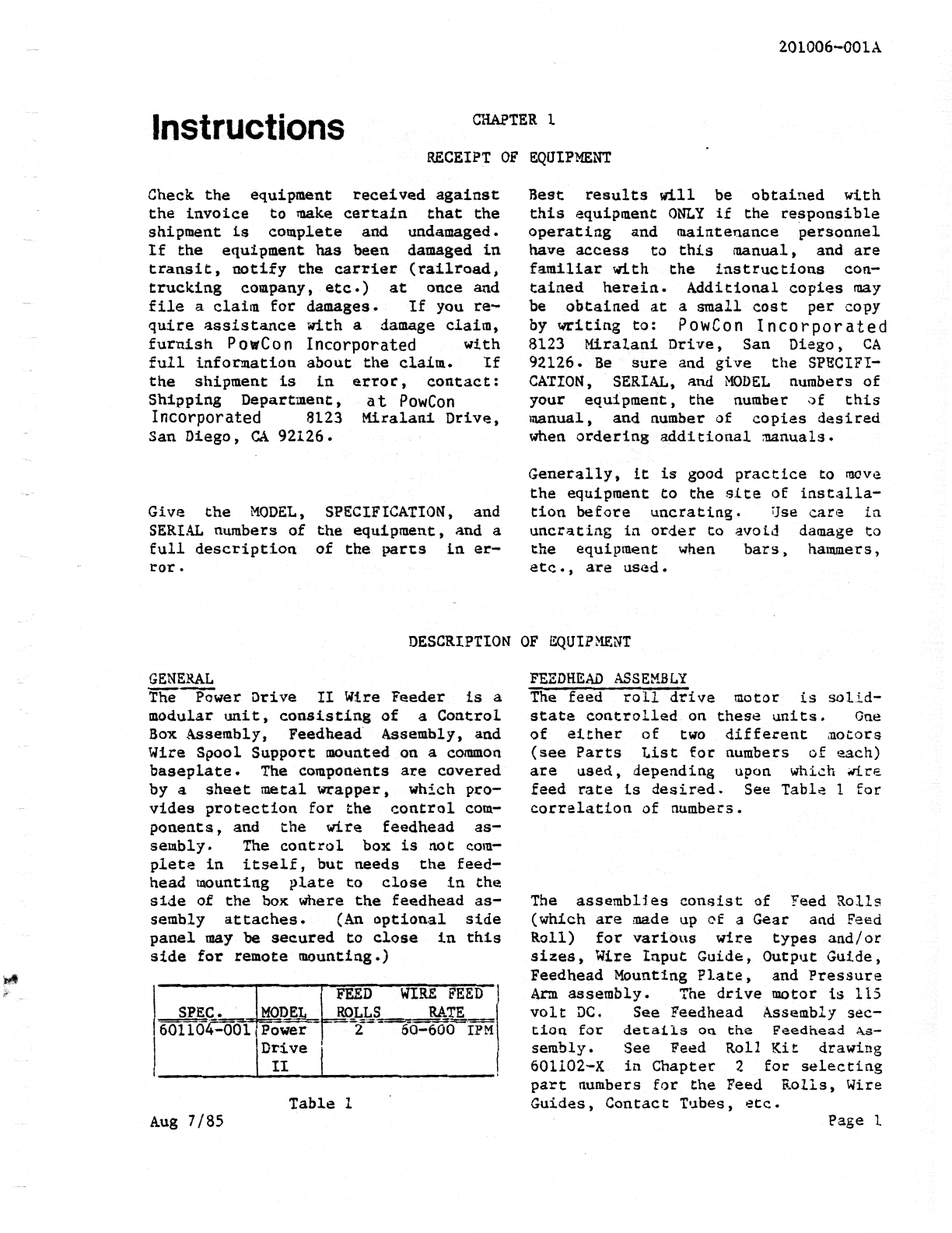
DESCRIPTION
OF
EQUIPMENT
General
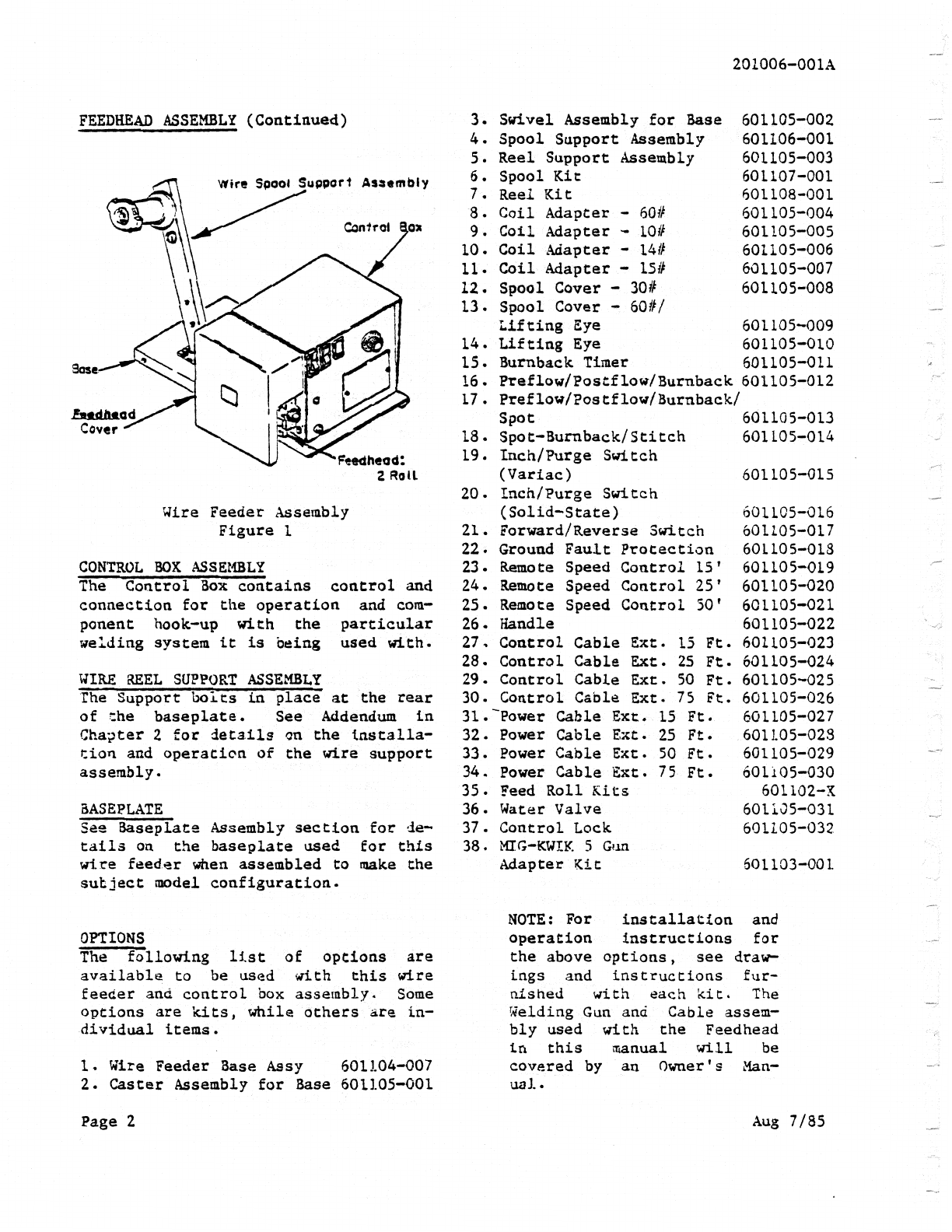
Feedhead Assembly
Control
Box
Assembly
Wire Reel
Support
Assemb2.y
Baseplate
Options
IN'STALLATION
OPERATION
Prewelding
Checks
Weldia.g
3
3
3
Control
Box
Feedhead Assembly
Baseplate
~Jire
Spool Support Asst:!mbl;•
CHAPTER
3 -
PARTS
LISTS
CHAPTER
4 -
DIAGRAMS
WARRANTY
Page
3