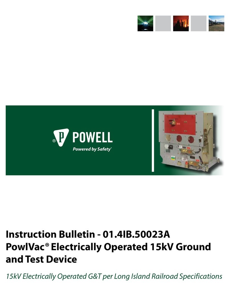
Powell POWLVAC 15PV63SASD User manual

IB-60030
Instructions
Installation Maintenance Renewal Parts
Powell Electrical Systems, Inc. •www.powellind.com
PowellApparatus Service Division (PASD) •http://www.powellservice.com
PO Box 12818, Houston, Texas 77217
•Tel: 713-944-6900 •Fax: 713-947-4453
©2001 Powell Electrical Systems, Inc. All rights reserved. 02/2005
POWLVAC®63kA
AUTOMATIC SECONDARY DISCONNECT (ASD)
CIRCUIT BREAKER
Model Number: 15PV63SASD

2
IB-60030
PowlVac®63kAASD Circuit Breaker
Contents
Section Page
I. INTRODUCTION .......................................................................................................................7
A. SCOPE ............................................................................................................................................... 7
B. PURPOSE .......................................................................................................................................... 7
C. INSTRUCTIONBULLETINSAVAILABLE ELECTRONICALLY............................................................ 7
II. SAFETY.......................................................................................................................................7
A. GENERAL ........................................................................................................................................... 8
B. SPECIFIC............................................................................................................................................ 8
C. X-RAYS ............................................................................................................................................... 8
D. SAFETY LABELS ............................................................................................................................... 8
III. EQUIPMENT DESCRIPTION...................................................................................................9
A. GENERALDESCRIPTION.................................................................................................................. 9
B. THE STORED-ENERGY MECHANISM ............................................................................................ 13
1) Mechanical Description................................................................................................................ 13
2) Electrical Description................................................................................................................... 14
C. RACKING MECHANISM ................................................................................................................... 19
1) GeneralDescription ..................................................................................................................... 19
2) StandardCircuitBreakerInterlocking ........................................................................................... 19
D. CIRCUIT BREAKER COMPARTMENTINTERFACES...................................................................... 20
1) PrimaryDisconnectingDevices ................................................................................................... 20
2) Secondary Disconnecting Device................................................................................................. 20
3) MOC (Mechanism-Operated Contact)Actuator............................................................................ 20
4) TOC(Truck-OperatedContact)Actuator ...................................................................................... 20
5) GroundConnection ...................................................................................................................... 20
6) Shutter Rollers............................................................................................................................. 20
7) Anti-Rollout Latch ........................................................................................................................ 20
E. VACUUM INTERRUPTERS .............................................................................................................. 20
F. VACUUM INTERRUPTER CONNECTION ........................................................................................ 20
IV. INSTALLATION ........................................................................................................................21
A. RECEIVING....................................................................................................................................... 21
B. HANDLING ........................................................................................................................................ 21
C. STORAGE......................................................................................................................................... 22
D. PLACING THE CIRCUIT BREAKER INTO SERVICE ...................................................................... 22
1) High VoltageInsulationIntegrity................................................................................................... 22
2) VacuumIntegrity.......................................................................................................................... 23
3) Control VoltageInsulation Integrity............................................................................................... 24
4) Mechanical Operation Check....................................................................................................... 25
5) Electrical Operation Check25
6) Racking Mechanism Check ......................................................................................................... 25
E. INSERTINGTHE CIRCUIT BREAKER INTOTHE METAL-CLAD SWITCHGEAR ........................... 26

3
PowlVac®63kAASD Circuit Breaker IB-60030
Contents
Section Page
1) Inserting theASD Circuit Breaker ............................................................................................... 26
2) Racking theASD Circuit Breaker ................................................................................................. 27
3) Through Door Racking Optionfor the ASD Circuit Breaker ......................................................... 30
4) Power Racking ............................................................................................................................ 31
V. MAINTENANCE........................................................................................................................32
A. GENERALDESCRIPTION................................................................................................................ 32
1) Introduction .................................................................................................................................. 32
2) Inspection and Cleaning............................................................................................................... 33
B. MECHANISMAREA ......................................................................................................................... 33
1) MechanicalOperation .................................................................................................................. 33
2) Lubrication ................................................................................................................................... 33
3) Main Closing Spring Removal, Slow Closing ofMechanism, and
Latch Check SwitchAdjustment.................................................................................................. 34
4) MechanismAdjustments ............................................................................................................. 36
5) Electrical Operation ..................................................................................................................... 37
C. VACUUM INTERRUPTERAND CONTACTAREA ............................................................................ 37
1) Vacuum Interrupter and ContactErosion...................................................................................... 37
2) VacuumIntegrity.......................................................................................................................... 37
3) MechanicalAdjustmentofVacuumInterrupters ........................................................................... 37
D. OPTIONAL MAINTENANCE PROCEDURES................................................................................... 38
1) High Potential Tests..................................................................................................................... 38
2) Timing .......................................................................................................................................... 38
3) Primary Resistance Check .......................................................................................................... 38
VI. RECOMMENDED RENEWAL PARTS AND REPAIR PROCEDURES ...............................42
A. ORDERINGINSTRUCTIONS ............................................................................................................ 42
B. RECOMMENDED RENEWAL PARTS ............................................................................................. 42
C. REPLACEMENT PROCEDURES..................................................................................................... 46
1) Vacuum InterrupterAssembly ...................................................................................................... 46
2) Closing CoilAssembly ................................................................................................................. 46
3) Primary ShuntTrip CoilAssembly ............................................................................................... 46
4) Secondary Shunt Trip CoilAssembly........................................................................................... 47
5) UndervoltageDeviceAssembly .................................................................................................... 47
6) Ground ConnectionAssembly ..................................................................................................... 47
7) Charging MotorAssembly............................................................................................................ 48
8) Anti-Pump RelayAssembly ......................................................................................................... 48
9) Latch Check Switch..................................................................................................................... 49
10) Motor Cutoff SwitchAssembly ..................................................................................................... 49
11) Auxiliary Switch........................................................................................................................... 50
12) Primary Disconnecting Device SpringAssembly.......................................................................... 50

4
IB-60030
PowlVac®63kAASD Circuit Breaker
Figures
Figure Page
Figure 1. PowlVac® 63kAASD Circuit Breaker ................................................................................................9
Figure 2. PowlVac® 63kAASD Circuit Breaker (Top and Side View) ..............................................................10
Figure3. PowlVac® 63kAASD Circuit Breaker (Rear View) .......................................................................... 11
Figure4. ASDCircuitBreaker-InteriorView(FrontCoverRemoved) .............................................................12
Figure5. CamandFundamental Linkage Positions........................................................................................16
Figure6. Mechanismand Trip Linkages .........................................................................................................16
Figure7. OperationSequence(StandardControl)...........................................................................................17
Figure8. TypicalControlScheme ...................................................................................................................18
Figure9. Circuit Breaker in ShippingCarton...................................................................................................21
Figure10. Circuit Breaker Shipping Bracket.....................................................................................................21
Figure11. Circuit Breaker and Fork Lift ............................................................................................................21
Figure12. Circuit Breaker and Crane ...............................................................................................................22
Figure13. ASD Circuit Breaker - Test Position.................................................................................................28
Figure 14. ASD Circuit Breaker - Racking HandleInsertion ..............................................................................28
Figure 15. Racking theASD Circuit Breaker.....................................................................................................28
Figure16. ASD Circuit Breaker Removal -Applying theAnti-RolloutLatch.......................................................29
Figure17. Through Door Racking Option for Circuit Breaker.............................................................................30
Figure18. MainClosing SpringAssembly Compressed for Removal ................................................................34
Figure19. MainClosingSpringAssembly Installed ..........................................................................................34
Figure20. Latch Check SwitchAdjustment.....................................................................................................35
Figure21. Primaryand SecondaryTrip PropAdjustment .................................................................................36
Figure22. PrimaryTripPropAdjusting Screw ..................................................................................................37
Figure23. Lubrication (1 of 2) ..........................................................................................................................40
Figure24. Lubrication (2 of 2) ..........................................................................................................................41
Figure25. Primary CurrentPath .......................................................................................................................43
Figure26. ControlDevices ...............................................................................................................................44
Figure27. Closing CoilAssembly.....................................................................................................................46
Figure28. Primary Shunt Trip CoilAssembly ...................................................................................................46
Figure29. Trip Lever GapAdjustment...............................................................................................................46
Figure30. UndervoltageDeviceAssembly ........................................................................................................47
Figure 31. Ground Connection ..........................................................................................................................47
Figure32. ChargingMotorAssembly................................................................................................................48
Figure33. Anti-PumpRelay .............................................................................................................................48
Figure34. Latch Check Switch.........................................................................................................................49
Figure35. Motor Cutoff SwitchAssembly.........................................................................................................49
Figure36. Auxiliary Switch...............................................................................................................................50
Figure37. PrimaryDisconnectingDeviceSpringAssembly..............................................................................50

5
PowlVac®63kAASD Circuit Breaker IB-60030
Tables
Figure Page
TableA. Field Dielectric Test Values ................................................................................................................ 23
TableB. Timing ................................................................................................................................................. 38
TableC. PrimaryResistance ............................................................................................................................ 38
TableD. Lubrication .......................................................................................................................................... 39
TableE. PrimaryCurrentPath .......................................................................................................................... 43
TableF. ControlDevices(1).............................................................................................................................. 44
TableG. Miscellaneous Parts ........................................................................................................................... 45

6
IB-60030
PowlVac®63kAASD Circuit Breaker
BEFORE ANY ADJUSTMENT, SERVICING, PARTS REPLACEMENT,
OR ANY OTHER ACT IS PERFORMED REQUIRING PHYSICAL
CONTACT WITH THE ELECTRICAL WORKING COMPONENTS OR
WIRING OF THIS EQUIPMENT, THE POWER SUPPLY MUST BE
DISCONNECTED. FAILURE TO FOLLOW THIS WARNING MAY
RESULT IN INJURY OR DEATH.
WARNING
!
THE EQUIPMENT DESCRIBED IN THIS DOCUMENT MAY CONTAIN
HIGH VOLTAGES AND CURRENTS WHICH CAN CAUSE SERIOUS
INJURY OR DEATH.
THE EQUIPMENT IS DESIGNED FOR USE, INSTALLATION, AND
MAINTENANCE BY KNOWLEDGEABLE USERS OF SUCH
EQUIPMENT HAVING EXPERIENCE AND TRAINING IN THE FIELD
OF HIGH VOLTAGE ELECTRICITY. THIS DOCUMENT, AND ALL
OTHER DOCUMENTATION SHALL BE FULLY READ,
UNDERSTOOD, AND ALL WARNINGS AND CAUTIONS SHALL BE
ABIDED BY. IF THERE ARE ANY DISCREPANCIES OR
QUESTIONS, THE USER SHALL CONTACT POWELL ELECTRICAL
MANUFACTURING COMPANY IMMEDIATELY AT 1-800-480-7273.
WARNING
!

7
PowlVac®63kAASD Circuit Breaker IB-60030
I. INTRODUCTION
A. SCOPE
Thisinstruction bulletin describes the following:
PowlVac®63kAAutomatic Secondary Discon-
nect Circuit Breaker (ASD) Model 15PV63kASD
B. PURPOSE
Thisinstruction bulletin is intended to provide the
informationrequiredtoproperlyoperateandmaintain
the PowlVac®63kA ASD Circuit Breaker described in
Section A. Scope.
Thisinstructionbulletinprovides:
1. Guidelinesforsafety
2. Generaldescriptionsoftheoperation and mainte-
nance of theAutomatic Secondary Disconnect
3. Instructions for installation and placing the circuit
breakersintoservice
4. Instructionsforpartreplacement
5. Renewal parts lists
It should be noticed that some of the illustrations
contained herein may not represent the exact con-
struction details of each particular type. These
illustrationsareprovided as general information to aid
inshowing component locations.
To the extent required, the productsdescribed herein
meet the applicableANSI, IEEE, and NEMAStan-
dards;however, no such assuranceis given with
respect to local codes and ordinances since the
specificationsvary greatly.
C. INSTRUCTION BULLETINSAVAILABLE
ELECTRONICALLY
Many Powell Electrical Manufacturing Company
Instruction Bulletins are posted on the company
Web site at www.powellind.com. For more informa-
tion contact PowellApparatus Service Division
(PASD) by phone at 1-800-480-7273, 713-944-6900,
II. SAFETY
Study this instruction bulletin and all other associated
documentationbeforeuncratingthePowlVac®63kA
ASDCircuit Breaker.
Each user has the responsibility to instruct and
superviseall personnel associated with usage, installa-
tion,operation, and maintenance of thisequipment on
allsafety procedures which must be observed. Fur-
thermore, each user has the responsibility of devising a
completesafety program for each type of equipment
encountered.
The circuit breaker described in this instruction bulletin
is operated by high energy, high speed mechanisms
interlockedtoprovide specific operating sequences.
To ensure the safety of personnel associated with
usage,installation,operation, and maintenance of
these circuit breaker, it is mandatory that the following
safetyrulesbeobserved. THESE RULES ARE NOT
INTENDED TO BE A COMPLETE SAFETY PRO-
GRAM, BUT ARE INTENDED TO COVER ONLYTHE
IMPORTANTASPECTS OF PERSONNEL SAFETY
RELATED TO POWLVAC®63kA ASD CIRCUIT
BREAKER.
THE INFORMATION IN THIS INSTRUCTION BULLETIN IS NOT INTENDED TO EXPLAINALL
DETAILS OR VARIATIONS OF THE POWLVAC 63kAASD CIRCUIT BREAKER, NOR TO PROVIDE
FOR EVERY POSSIBLE CONTINGENCY OR HAZARD TO BE MET IN CONNECTION WITH
INSTALLATION, TESTING, OPERATION, AND MAINTENANCE OF THE EQUIPMENT. FOR
ADDITIONALINFORMATION AND INSTRUCTIONS FOR PARTICULAR PROBLEMS, WHICH ARE NOT
PRESENTED SUFFICIENTLY FOR THE USER’S PURPOSES, CONTACT POWELLELECTRICAL
MANUFACTURING COMPANYAT 1-800-480-7273.
IMPORTANT
!

8
IB-60030
PowlVac®63kAASD Circuit Breaker
A. GENERAL
1. Onlysupervisedandqualifiedpersonneltrainedin
theusage, installation, operation, and maintenance
of the circuit breaker shall be allowed to work on
this equipment. It is mandatory that this instruc-
tionbulletin, any supplements, and service adviso-
riesbe studied, understood, and followed.
2. Maintenance programs must be consistent with
bothcustomerexperienceand manufacturer’s
recommendations,includingserviceadvisoriesand
theinstruction bulletin(s). Awell-planned and
executedroutine maintenance program is essential
for circuit breaker reliability and safety.
3. Serviceconditionsandcircuit breaker applications
shallalso be considered in the development of
suchprograms, including such variables as
ambienttemperature and humidity, actual continu-
ouscurrent, thermal cycling, number of operations,
interrupting duty, and any unusual local conditions
such as excessive dust, ash, corrosive atmo-
sphere,vermin,and insect problems.
B. SPECIFIC
1. DO NOT WORK ON AN ENERGIZED CIRCUIT
BREAKER. Ifwork must be performed on a circuit
breaker,removeitfromserviceandremoveitfrom
themetal-cladswitchgear.
2. DO NOT WORK ON A CIRCUIT BREAKER WITH
THECONTROLCIRCUIT ENERGIZED.
3. EXTREME CARE MUST BE EXERCISED TO
KEEP ALL PERSONNEL, TOOLS, AND OTHER
OBJECTS CLEAR OF MECHANISMS WHICH
ARE TO BE OPERATED, DISCHARGED, OR
RELEASED. Thecircuitbreaker utilize stored-
energy mechanisms. These mechanisms must be
servicedonly by skilled and knowledgeable
personnelcapable of releasing each spring load in
acontrolledmanner. Detailedinformationregard-
ing these mechanisms is found in this instruction
bulletin.
4. DO NOTATTEMPT TO CLOSE THE CIRCUIT
BREAKER MANUALLY ONAN ENERGIZED
CIRCUIT.
5. DO NOT USE AN OPEN CIRCUIT BREAKER
AS THE SOLE MEANS OF ISOLATINGA HIGH
VOLTAGE CIRCUIT. For complete isolation, the
circuit breaker shall be in the disconnected
position or shall be withdrawn completely.
6. ALL COMPONENTS SHALL BE DISCON-
NECTED BY MEANS OF A VISIBLE BREAK
AND SECURELY GROUNDED FOR THE
SAFETY OF PERSONNEL PERFORMING
MAINTENANCE OPERATIONS ON THE CIR-
CUITBREAKER.
7. Interlocksareprovidedtoensurethe proper
operatingsequences of the circuit breaker andfor
the safety of the user. If for any reason an inter-
lock does not function as described, do not make
any adjustments, modification, or deform the parts.
DO NOT FORCE THE PARTS INTO POSITION.
CONTACT POWELL ELECTRICALMANUFAC-
TURING COMPANY FOR INSTRUCTIONS.
C. X-RAYS
When high voltage is applied across the contacts of a
vacuuminterrupter, there isthe possibility of generation
of X-rays. The intensity of this radiation is dependent
on the peak voltage and the contact gap. At the
normaloperating voltage for this type of equipment, the
radiationlevels are negligible. At the voltagesspecified
for testing, test personnel shall be in front of the circuit
breaker such that the two layers of steel used in the
frameand front cover construction arebetween the test
personneland the vacuum interrupters, and that the
test personnel be no closer than one meter from the
frontofthecircuit breaker. THE CIRCUIT BREAKER
SHALL BE EITHER FULLY OPEN, OR FULLY
CLOSED WHEN MAKING HIGH POTENTIAL
TESTS. DO NOT TEST WITH THE CONTACTS
PARTIALLY OPEN.
D. SAFETY LABELS
ThecircuitbreakerhasDANGER, WARNING, CAU-
TION, and instruction labels attached to various
locations. Allequipment DANGER, WARNING,
CAUTION,and instruction labelsshall beobserved
when the automatic secondary disconnect is handled,
operated,ormaintained.

9
PowlVac®63kAASD Circuit Breaker IB-60030
III. EQUIPMENT DESCRIPTION
A. GENERAL DESCRIPTION
PowlVac®circuitbreakers use sealed vacuum interrupt-
ers (Figure 3, f) to control the primary circuit. The
primary connections to the associated metal-clad
switchgearare made by parallel copper busbars
terminating in multiple contact fingers of the primary
disconnecting devices (Figure 3, d and g). The primary
disconnectingdevices,busbars,andvacuum inter-
rupterassemblies are supported by insulators (Figure
3, e) specifically designed for the application.
The primary current path side of the circuit breaker is
considered the rear of the circuit breaker, while the
sidewith the cover containing the variousindicators
andmanual operators is considered the front of the
circuitbreaker. Byremoving the front cover, the
operatingmechanisms of the circuit breaker are
exposed. Thestored-energy mechanism assembly
providesmotiontoeachofthe vacuum interrupter
movingcontactassembliesthroughoperatingpushrods
(Figure 3, r). In the same metal enclosed compartment
as the stored-energy mechanism is the circuit breaker
racking mechanism and interlocks which control the
movement of the circuit breaker between the test/
disconnected and connected positions. The racking
mechanismprovidesthemotiontoengage/disengage
theprimary disconnecting devices and to open/close
the shutters in metal-clad switchgear.
Figure 1. PowlVac®63kA ASD Circuit Breaker
a. Cover Bolts
b. Front Cover
c. Name Plate
d. MOC Actuator
e. Handle
f. Operations Counter
g. Manual Charging Crank
h. Spring Charge Indicator
i. Manual Close Operator
j. Open/Close Indicator
k. Manual Trip Operator
l. Padlock Provision - Latch for Movable Arm
m. Padlock Provision - Movable Arm
n. Racking Drive Shaft Shutter
o. Position Indicator
p. TOC Actuator
f
a
p
d
b
e
l
jg
q
c
ik
s
h
t
n
o
uv
m
q. Secondary Disconnect Plug
r. Secondary Disconnect
Handle
s. Pin Guide
t. Slider
u. Pivotal Lock
v. Wiring Bundle
r

10
IB-60030
PowlVac®63kAASD Circuit Breaker
a
Figure 2. PowlVac®63kA ASD Circuit Breaker (Top and Side View)
a. Secondary Disconnect - Pins
b. Serial Number Plate
c. Ground Connection
b
c

11
PowlVac®63kAASD Circuit Breaker IB-60030
a. Support Strut
b. Main Insulator (Wishbone)
c. Inboard Radiator
d. Upper Primary Disconnecting Device
e. Insulating Pole Support
f. Vacuum Interrupter
g. Lower Primary Disconnecting Device
h. Frame
Figure 3. PowlVac®63kA ASD Circuit Breaker (Rear View)
b
c
i
j
d
e
f
g
h
a
(ASD Back View with
Barriers Removed)
i. Wheel
j. Anti-Rollout Latch
k. Crank Arm Roller
l. Racking Crank Arm
m. Racking Shaft
n. Racking Drive Shaft
o. Worm Gear
p. Bell Crank
q. Jackshaft Pin
r. Operating Pushrod
s. Contact Loading Spring
t. Spring Yoke
u. Lock Nut
v. Operating Pin
w. Lower Vacuum Interrupter Casting
w
v
u
q
p
ts
r
(ASD Side View with Barriers Removed)
o
nm
l
k

12
IB-60030
PowlVac®63kAASD Circuit Breaker
Figure 4. ASD Circuit Breaker - Interior View (Front Cover Removed)
a. Anti-Pump Relay
b. Opening Spring
c. Shock Absorber (Dashpot)
d. Primary Shunt Trip Coil
e. Anti-Bellows Springs
f. MOC Actuator
g. Auxiliary Switch
h. Charging Motor
i. Connecting Rod
j. Main Closing Spring
k. Wiring Harness
l. Main Trip Shutter Interlock
m. Secondary Disconnect Trip Arm Assembly
n. Anti-Rollout Latch
o. Motor Cutoff Cam
p. Charging Motor Drive Shaft
q. Motor Cutoff Switch
r. Close Bar Adjusting Screw
s. Latch Check Switch
t. Jackshaft
u. Crank Pin
v. Crank Arm
w. Secondary Trip Prp Adjusting Screw
x. Holding Pawl Support Arm
y. Holding Pawl Adjusting Eccentric
z. Closing Coil
aa. Reset Spring
ab. Main Closing Cam
ac. Secondary Trip
Prop
ad. Main Cam Roller
ae. Camshaft
af. Pawl Lift Plate
ag. Drive Pawl
ah. Pawl Support Arm
ai. Close Latch Shaft
aj. Close Latch Arm
ak. Ratchet Wheel
ac
ab
aa
ad
aeaf
ag
ah ai
aj
ak
t
ux
y
z
s
v
w
o
p
q
r
a
b
c
d
e
h
i
j
g
f
k
l
n
m

13
PowlVac®63kAASD Circuit Breaker IB-60030
B. THE STORED-ENERGY MECHANISM
1) Mechanical Description
Thestored-energy mechanism is located in the front of
thecircuit breaker behind the front cover. The front
cover is held in place by ten (10) cover bolts that may
beremoved, allowing access to the stored-energy
mechanism and its interlocks, auxiliary switches,
racking mechanism, and other control devices. It is
very important to ensure that the circuit breaker is in
theOPEN position and the main closing spring (Figure
4,j is fully discharged before removingthe front cover.
FAILURE TO DO THIS MAY RESULT IN INJURY.
Onthe escutcheon of the stored-energy mechanism,
thereare two (2) indicatorsthat show the various
states of operation of the mechanism and two (2)
manualoperators that will open/close the stored-
energymechanism. The circuit breaker nameplate
(Figure 1, c) is also located on the mechanism es-
cutcheon. If for any reason the escutcheon is removed
from the circuit breaker, it shall be verified that the
serialnumber contained on the nameplate matches the
engravedserialnumberplate(Figure2,b)permanently
affixed to the rear of the circuit breaker frame prior to
installing the escutcheon.
The mechanism employed in the circuit breaker is a
stored-energy system which uses a charging motor to
compress the main closing spring. During the closing
operation the energy stored in the main closing spring
is released. This allows the mechanism to close the
vacuum interrupter contacts, compress the contact
loadingsprings, charge the opening springs, extend
theanti-bellowssprings (Figure 4, e), and overcome
frictional forces. When the circuit breaker is opened,
the energy stored in the opening and contact loading
springsis released, and the vacuum interruptercon-
tactsare opened.
Thecharging motor (Figure 4, h), located on the
bottom right of the base pan, is assembled to the
circuit breaker by a bracket that is bolted to the base
pan. The charging motor drive shaft inserts into the
eccentric drive shaft. The eccentric drive shaft is
supportedby needle roller bearings in the mechanism
frame side sheets and transmits the motor torque to
the left side of the mechanism.
When the charging motor is energized, the eccentric
drive shaft rotates and causes the pawl support arms
topivot about the camshaft (Figure 4, ae). The drive
pawl, which is supported by the arms, engages with
theratchet wheel and drives theratchet wheel one
tooth at a time. To prevent backwards motion of the
ratchetwheel, a spring-loaded holding pawl is used to
latchthe ratchet wheel after each advance from the
drivepawl.
To ensurecorrect synchronization of the drive and
holdingpawl, the position of the holding pawl support
arms are adjustable by the holding pawl adjusting
eccentric (Figure 4, y) located at the left front of the
mechanism. When the mechanism is operated
manually, the top pawl becomes the drive pawl and the
bottompawl becomes the holding pawl.
Theratchet wheel (Figure 4, ak) has projections from
its side faces which engage the drive plates as it
rotates. These drive plates are attached to the cam-
shaft, thus causing the camshaft to rotate. Attached
to the ends of the camshaft are crank arms (Figure 4,
v). Crank pins (Figure 4, u) are assembled to the
crank arms, which point outward. The crank arms
engagethe bottom ends of the connecting rods (Figure
4, i ). The pins that project from the spring yoke,
which straddles the main closing spring, engage the
top ends of the connecting rods. As the camshaft
rotates the connecting rods will pull the spring yoke
downward,compressing the main closing spring.
The ratchet wheel will drive the camshaft so that the
connecting rods go down to their lowest position, and
then start to move upward. At a certain point, the
springforcewill overcome friction and resistance and
start to rotate the camshaft. At the same time, the
pawlsare uncoupled from the ratchet wheel by the
pawl lift plate (Figure 4, af) and the motor cutoff switch
is operated. The motor cutoff switch (Figure 4, q),
located at the right of the mechanism, is operated by
thespring charge indicator and motor cutoff cam
(Figure 4, o). The spring charge indicator (Figure 1, h)
will display that the mechanism is charged.
The camshaft would continue to rotate, except that it is
restrained by the close latch arm (Figure 4, aj) engag-
ing against the close latch shaft (Figure 4, ai). The
main closing cam, located between the mechanism
side sheets, is now in a position where the fundamen-
tal linkage can move to the reset position.

14
IB-60030
PowlVac®63kAASD Circuit Breaker
The close latch, when released either by the closing
coil or the manual close operator, allows the main
closing spring to pull the crank arms upward thus
rotatingthe main closing cam and driving the funda-
mental linkage into the closed position. This causes
the main linkage to rotate the jackshaft such that the
operatingpushrods(Figure3,r)aredriventowardthe
current carrying side of the circuit breaker.
Each operating pushrod assembly has a recess at
each end which encloses a contact loading spring
(Figure 3, s). At the end of this spring is a spring yoke
(Figure 3, t), which connects with bell cranks. The
spring yoke is restrained by a lock nut on a stud which
passes through the contact loading spring and is
attached to the operating pushrod assembly. The
contact loading spring has initial compression such
that as soon as the vacuum interrupter contacts touch,
the springs are preloaded to a value sufficient to resist
vacuuminterruptercontactseparationunderthe
highestelectromagnetic forces exerted by the rated
short-circuitcurrent. Further movement of the operat-
ing pushrod assembly compresses the contact loading
springevenmoreand produces a gap between the face
of the spring yoke and the lock nut. This nut gap is
usedtoevaluatetheerosion of the vacuum interrupter
contacts.
For each phase, bell cranks (Figure 3, p) are located
on the inside of the lower primary disconnecting
devices(Figure 3, g) and are supported bybearings.
Each bell crank is connected to an operating pin,
which passes through a slot in the lower primary
disconnectingdevices and engage an extensionto the
vacuuminterrupterassemblythusmovingthevacuum
interruptercontact. The bell cranks give an approxi-
mate 3 to 1 multiplication of the contact loading spring
force, enabling a lower spring rate to be used. It also
multiplies the contact movement by a factor of approxi-
mately 3, so that the mechanism linkages have
relativelylarge movements and are lesscritical.
In the cam and fundamental linkage positions shown in
Figure 5 b and 5 d, the contact loading springs and the
main opening springs are both acting to compress the
three (3) main mechanism links. The jackshaft ex-
tends from the left to the right side of the circuit
breaker frame and is supported at the main circuit
breaker frame side sheets and by the mechanism side
sheets. Theouter operating levers on the jackshaft
haveconnections to the circuit breaker opening springs
(Figure4, b).
Thefundamentallinkageisrestrainedfrommovement
by the secondary trip prop acting on the primary trip
prop roller. Acomponent of force tends to make the
primary trip prop rotate upward, but it is restrained by
the secondary trip prop face acting on the primary trip
proproller. Theclearancebetween the primary trip
prop roller and the secondary trip prop is controlled by
the primary trip prop adjusting screw. When the trip
shaft is rotated by the action of the manual trip opera-
tor or the primary shunt trip coil, the secondary trip
propfacemovesdownward and permits the primary trip
prop to rotate upward, thus permitting the main linkage
tomove upward and the jackshaftto rotate, opening
the circuit breaker. The left jackshaft levers engage a
shock absorber (Figure 4, c), which controls the
reboundofthe vacuum interrupter contacts on an
opening operation. An extension of the jackshaft
projects through the left circuit breaker side sheet and
operates the MOC actuator (Figure 1, d).
With the electrical control scheme, as soon as the
main closing spring is discharged on a closing opera-
tion, the charging motor is switched on to recharge the
springs. This leaves the main closing cam in a
positionwhere a tripped linkagecan reset under the
action of the reset spring (Figure 4,aa) and the primary
and secondary trip props can fall into the reset posi-
tion. The reset spring stretches between an extension
of the main cam roller pin and a spring support pin
located on the left mechanism side sheet. The latch
check switch (Figure 4, s), operated by a lever on the
trip shaft, will close as the secondary trip prop reaches
the fully reset position.
2) Electrical Description
a) Charging Motor
The function of charging motor (Figure 4, h) is to
compressthe main closing spring of the stored-energy
mechanism,thus providing the necessary energy to
close the circuit breaker. The charging motor, located
at the bottom right of the base pan, is assembled to
the circuit breaker by a bracket that is bolted to the
basepan.
b) Motor Cutoff Switch
Themotor cutoff switch (Figure 4, q) providesan
electrical break in the control circuit supplying the
charging motor when the main closing spring is fully
chargedand the stored-energy mechanism is ready for
a closing operation. It is located at the bottom right of
the mechanism, and is supported by a bracket which
is bolted to the circuit breaker base pan.

15
PowlVac®63kAASD Circuit Breaker IB-60030
c) Anti-Pump Relay
Theanti-pumprelay (Figure 4, a) provides a logic
function for the control circuit which prevents a continu-
ous electrical close signal from causing the circuit
breaker to continuously re-close after a trip signal.
The anti-pump relay is located on the circuit breaker
frame, left of the connecting rod, and is supported by
two screws.
d) Operating Solenoids
Electrical operation of the circuit breaker is accom-
plishedusingoperating solenoids.
The closing coil (Figure 4, z) is an operating solenoid
that is located at the bottom center of the mechanism,
and is assembled to the circuit breaker base pan by
boltsaccessiblefromunderneath the circuit breaker.
The primary shunt trip coil (Figure 4, d) is located at
the top left side of the mechanism, and is assembled
to the lower frame channel by two bolts.
Either a secondary shunt trip coil or an undervoltage
device may be furnished as an option. When fur-
nished, either of these devices will be located at the
top right side of the mechanism, installed on the lower
frame channel. Only one of these two operating
solenoids may be furnished on any one circuit breaker,
as both devices are located in the same space.
e) Control Circuit
A typical DC electrical control scheme is shown in
Figure 8. The control scheme of any particular circuit
breakermay differ from the typical scheme depending
onthe user’s requirements, operating solenoids, and
the control devices furnished with that circuit breaker.
Thesequence of operation for all control schemes is
shown in Figure 7. Circuit breaker mounted auxiliary
contacts not used in the control circuit are brought out
forcontrol and indication functions. The metal-clad
switchgearequipmentmay provide a circuit breaker
MOC(Mechanism-OperatedContact)foradditional
contacts.
(THIS SPACE IS BLANK INTENTIONALLY.)

16
IB-60030
PowlVac®63kAASD Circuit Breaker
Figure 6. Mechanism and Trip Linkages
a. Secondary Trip Prop Adjusting Screw
b. Secondary Trip Prop Shaft
c. Secondary Trip Prop
d. Secondary Linkage Roller
e. Main Cam Roller
f. Reset Spring
g. Camshaft
h. Main Closing Cam
i. Center Phase Operating Lever
j. Jackshaft
k. Primary Trip Prop Roller
l. Primary Trip Prop Adjusting Screw
m. Primary Trip Prop
Figure 5. Cam and Fundamental Linkage Positions
3 c. 3 d.
3 b.
3 a.

17
PowlVac®63kAASD Circuit Breaker IB-60030
Figure7. Operation Sequence (Standard Control)
SECONDARY
DISCONNECT
MAKES
CLOSE SPRING
CHARGED
BREAKS
LS
MAKES
LCS
ENERGIZED
GREEN LIGHT
WHITE LIGHT
ENERGIZED
"Y" CIRCUIT
DISABLED
"CS/C" MAKES
CLOSE CONTROL
CLOSE COIL "CC"
ENERGIZED
DISCHARGED
CLOSE SPRING
MOTOR "M"
ENERGIZED
DE-ENERGIZED
WHITE LIGHT
LS
MAKES
BREAKS
LSLS
MAKESBREAKS
LS
PREVENTS
CLOSE COIL
MOTOR "M"
DE-ENERGIZED
ENERGIZED
WHITE LIGHT
LS
BREAKS
MAKES
LS
CHARGED
CLOSE SPRING
VCB CLOSED
BREAKS
52/b
"Y" COIL
ENERGIZED DE-ENERGIZED
CLOSE COIL "CC"
ENERGIZATION
BEFORE
FULLY CHARGED
SPRING IS
RELEASED
SWITCH IS
BEFORE CONTROL
IF VCB TRIPS
PUMPING
PREVENTS
BREAKS
"Y" CONTACT
MAKES
"Y" CONTACT
"Y" COIL
"SEALS IN"
LS
BREAKS MAKES
LS
52/a
MAKES
GREEN LIGHT
DE-ENERGIZED
BREAKS
52/b
ENERGIZED
RED LIGHT
TRIP CIRCUIT
SET UP
CONTROL SWITCH
"CS/C" BREAKS
RELEASE CLOSE
DE-ENERGIZED
"Y" COIL
MAKES
LS
MOTOR "M"
ENERGIZED
DE-ENERGIZED
MOTOR "M"
BREAKS
LS
MAKES
LS
Figure 7. Operation Sequence (Standard Control)

18
IB-60030
PowlVac®63kAASD Circuit Breaker
Figure 8. Typical Control Scheme
LS = SpringChargeLimit Switch (shown with
springdischarged)
LCS = Latch Check Switch (shown with spring
discharged)
Y = Anti-PumpRelay
TC = Breaker Trip Coil
CC = Breaker Close Coil
M = ChargingMotor
52/a = BreakerAuxiliary Contact (normally open)
52/b = BreakerAuxiliary Contact(normallyclosed)
SD = BreakerSecondary Disconnect ( )
DEVICE IDENTIFICATION
^
^
TO RATED
CONTROL POWER
TO RATED
CONTROL POWER
CLOSE TRIP
TO RATED
CONTROL POWER
PINS NOT USED
PINS NOT USED
125VDC/120VAC 125VDC
125VDC
125VDC
a
a
a
a
b
b
bab
9111213
15
13
19
10 14
16
4
20
17
2
5
6
7
8
21
22
23
24
18
MTC
CC
Y
LS
LS
LS
Y
LCS
LS
52
52
52
52
52
52
52 52 52

19
PowlVac®63kAASD Circuit Breaker IB-60030
C. RACKING MECHANISM
1) General Description
The racking mechanism is the mechanical assembly
that facilitates moving the circuit breaker between the
breakertest/disconnected and the connected positions
in the circuit breaker compartment. The main racking
mechanism components for theASD circuit breaker is
shown and described in the following sections.
a) Breaker Position Indicator
Thebreaker position indicator (Figure 1, o) is visible
throughanopening in the circuit breaker front cover.
The indicator displays whether the circuit breaker is in
the connected or the test/disconnected positions.
When the breaker position indicator displays
BREAKER CONNECTED,andthisis fully visible in the
aperture, the circuit breaker is in the connected
position. When the breaker position indicator displays
BREAKER TEST/DISCONNECTED, and this is fully
visible in the aperture, the circuit breaker is in the test/
disconnected position. In positions other than the
connected and test/disconnected positions, the
breaker position indicator does not display an indica-
tion. Refer to the section Inserting the Circuit Breaker
intotheCircuit Breaker Compartment for more informa-
tion.
b) Interlocking
PowlVac® ASD circuit breakers areprovided with
interlocks that operate in conjunction with the circuit
breakercompartmenttoensuretheproper operation of
the circuit breaker. Do not attempt to modify or
bypass these interlocks, as they are necessary for the
safeoperation of the circuit breaker. The following
describes the interlocking for theASD circuit breaker.
The purpose of the interlocks is to ensure the following:
1. Thecircuitbreaker cannot be moved from the test/
disconnected to the connected position unless the
main circuit breaker contacts are opened and the
circuitbreaker cannot be removed from the con-
nected to the TEST /DISCONNECTED position
unless the main contacts are opened.
2. Thecircuitbreakercannotberemoved from the
circuit breaker compartment with the circuit
breaker CLOSED orwith the main closingspring
charged.
2) Standard Circuit Breaker Interlocking
TheASD circuit breaker interlocking is primarily
achievedby means of a racking drive shaft shutter.
A racking drive shaft shutter on the front of the circuit
breaker restricts access to the racking drive shaft. The
shuttercannotbemoved downward until the manual
trip operator is pushed inward. This assures that the
circuit breaker is OPEN prior to allowing access to the
rackingdriveshaft.
The shutter is pivoted on the frame of the circuit
breaker and has a projecting pin that engages a slot in
a cam on the racking shaft. This cam has two (2)
slots arranged so that the shutter can only be in its
upwardposition when the racking crank arms are fully
intheTEST/DISCONNECTED or CONNECTED
position. Since the manual trip operator is mechani-
cally held in the inward (actuated) position when the
shutter is down, and the shutter can be raised in only
theTEST/DISCONNECTED orCONNECTEDpositions
due to the pin and cam arrangement, the circuit
breaker is held in a trip-free condition in any position
except the test/disconnected or connected position.
The manual trip operator also actuates the latch check
switch, thus blocking any electrical closing signal.
The anti-rollout latch also actuates the secondary trip
prop shaft and the close latch. This final interlock
ensures that the circuit breaker is in the open position
and the main closing spring is discharged prior to
removalfromthecompartment.
a) ASD Racking Mechanism
TheASD racking mechanism consists of a racking
shaft (Figure 3, m) with racking crank arms (Figure 3,
k) at each end, which are supported by the frame side
sheets. The racking shaft also supports a worm gear
assembly (Figure 3, o) at the right end just inside the
right side sheet. In addition, the racking crank arms
have rollers attached to each end of the racking shaft,
which engage the vertical slots of the racking hooks in
the circuit breaker compartment. Rotation of the
racking crank arms will drive the circuit breaker into or
out of the connected position. This action also oper-
ates the compartment shutters. As the racking drive
shaft rotates, the worm rotates the worm gear until the
threadedplate which moves along the racking shaft
encounters either a front or back sleeve attached to the
shaft is prevented by any further rotation. At this time,
the breaker position indicator on the front of the circuit
breakerwilldisplayBREAKER CONNECTED, or
BREAKERTEST/DISCONNECTED.
In addition, a bolt on the left side sheet serves as a
backupto the threaded plate, providing a positive stop
to the left crank arm. This positive stop prevents
furtherrotation of the racking shaft, thus stopping
circuit breaker travel. At this time, the breaker position

20
IB-60030
PowlVac®63kAASD Circuit Breaker
indicator on the front of the circuit breaker will display
BREAKERCONNECTED.
D. CIRCUIT BREAKER COMPARTMENT
INTERFACES
1) Primary Disconnecting Devices
Thereare six primary disconnecting devices on the
circuit breaker. They are arranged, two per phase, with
the upper device connected to the stationary end of the
vacuuminterrupter, and the lower device connected to
themovingend of the vacuum interrupter assembly.
Eachprimary disconnecting device (Figure 3, d and g)
has multiple contact fingers which will mate with the
stationary primary disconnecting devices in the circuit
breakercompartment. DO NOT HANDLE OR MOVE
THECIRCUITBREAKER BY THE PRIMARYDISCON-
NECTING DEVICES,AS DAMAGE MAYOCCUR.
2) Secondary Disconnecting Device
Controlpoweristransferred from the metal-clad
switchgear to the circuit breaker by means of the
secondarydisconnect device. The secondary discon-
nect plug (Figure 1, q) is located on the top side of the
circuit breaker. The secondary receptacle plug is
attached to the switchgear and is located on the shelf
abovethe circuit breaker. This arrangement allows the
secondary connection to be visible in all positions of
thecircuit breaker.
3) MOC (Mechanism-Operated Contact)
Actuator
The MOC, located in the switchgear, is operated by a
leverwhichextends from the circuit breaker operating
mechanism. Movementof the MOC actuator (Figure 1,
d) is directly related to the movement of the circuit
breaker mechanism and contacts.
4) TOC (Truck-Operated Contact)Actuator
The TOC, located in the switchgear, is operated by
circuit breaker truck position. To accomplish this, a
TOC actuator (Figure 1, p) is located on the right top of
the circuit breaker frame and it is designed to strike
the TOC as the circuit breaker travels to the connected
position.
5) Ground Connection
Thegroundconnection is an assembly of spring-loaded
fingersthateffectively grounds the circuit breaker frame
as it is inserted into the circuit breaker compartment.
The ground connection (Figure 2, c) is located at the
rearedge of the floor pan of the circuit breaker between
the center and right poles of the circuit breaker. An
extension of the metal-clad switchgear ground bus is
securedto the circuit breaker compartment floor and
engagesthe ground connection as the circuit breaker
is placed into the disconnected position. The ground
connectionsystem remains engaged in all subsequent
positions of the circuit breaker until the circuit breaker
isremovedfrom the compartment.
6) Shutter Rollers
Thecircuit breaker travels between the test/discon-
nected and connected positions as the crank arm
rollers (Figure 3, k) engage the vertical slots of the
racking cams attached in the circuit breaker compart-
ment. This action also drives the compartment
shutters to open/close which allows the primary
disconnectingdevices to connect/disconnect. Down-
ward movement of the crank arm rollers in the slots will
move the shutters to the fully open position before the
circuitbreaker travels towards the connected position.
7) Anti-Rollout Latch
Thecircuitbreakerisequippedwith ananti-rolloutlatch
(Figure3,j)whichpreventsinadvertentremovalfromthe
circuit breaker compartment by engaging a block in the
circuitbreakercompartment. The anti-rollout latchalso
actuates the secondary trip prop shaft and the close
latch. This final interlock ensures that the circuit breaker
is in the open position and the main closing spring is
dischargedpriortoremovalfromthecompartment.
E. VACUUM INTERRUPTERS
PowlVac®circuitbreakers utilize sealed vacuum
interrupters to control the primary circuit. Some
vacuuminterrupters appear to be identical in size and
shape externally, but types vary in ratings due to the
differencesin their internal construction.
F. VACUUM INTERRUPTER CONNECTION
Connectiontothevacuuminterrupterstemsaremadeby
meansofcoppervacuuminterruptercastings. Thetop
stemofthevacuuminterrupteris fixedandacopper
vacuuminterruptercastingisfastenedtothestem. The
upperprimary disconnectingdevicesarethenassembled
tothevacuuminterruptercasting. Anothercopper
vacuuminterrupter castingwithprimarydisconnecting
devicesis mounted to the bottom or moving stem of the
vacuuminterrupter. Themulti-contactbandsinside the
lowervacuuminterruptercastingmakecontact withthis
castingandthemovingstem ofthevacuum interrupter.
Themultipleparallel pathsofthemulti-contact bands
keep the current density low.
Table of contents
Other Powell Circuit Breaker manuals

Powell
Powell PowlVac ARG 4 Series Training manual

Powell
Powell PowlVac 38 ARM 3000A 4 Series Training manual

Powell
Powell PowlVac 01.4IB.50032C User manual

Powell
Powell PowlVac IB-60201 User manual

Powell
Powell PowlVac IB-65020A CDR 27kV User manual

Powell
Powell PowlVac ARG 4 Series Training manual

Powell
Powell IPS PowlVac IB-60202 CDR User manual

Powell
Powell PowlVac ASD User manual
Popular Circuit Breaker manuals by other brands

Eaton
Eaton Power Defense PDG2XPIBB3P225A Instruction leaflet

L&T Electrical & Automation
L&T Electrical & Automation OMEGA manual

OEZ
OEZ MINIA MMR-X3-001-A230 Instructions for use

WEG
WEG SSW900-CRS485-W user guide

Allis-Chalmers
Allis-Chalmers LA-1600 instructions

Siemens
Siemens 8BT2 Installation and operating instructions