Allis-Chalmers LA-1600 User manual

A
CONTROLS
ALUS-CHALMIRS
'INSTRUCTIONS
AIR CIRCUIT BREAKER
•
TYPE LA-1600 & LA-1600F (FUSED)
,
!
---------
,
8WX-6638-6
1SX4582

INDEX-----------------------------------------------------------
INSTALLATION AND INSPECTION. . . . . .
..
I
Introduction
..........................
I
Receiving and Inspection for Damage
..........
I
Installation . . . . . . . . . . . . . . . . . . . . . . . .
..
I
Storage
..............................
I
Maintenance
..........................
3
OPERATION 3
Description. . . . . . . . . . • • . . • . . . . . . . . . . .
..
3
Manually·Operated Breaker
..............
3
Electrically·Operated Breaker. . . . . . . . . . . .
..
4
Racking Mechanism, Drawout Interlock, and
Lifting Bar . . . . . . . . . . . . . . . . . . . . . . . .
..
6
Spring Discharge Mechanism . . . . . . . . . . . .
..
7
Description and Function
................
7
Adjustments
........................
7
MAINTENANCE AND ADJUSTMENTS. . . .
..
9
Maintenance
Lubrication 9
9
Maintenance Closing . . . . . . . . . . . . . . . . . . . . . 9
Adjustments
.........................
II
Trip·Latch Engagement
................
,
II
Main Contact Make
...................
II
Arcing Contact Make
.................
II
Electrically-Operated Breakers
...........
II
Contact Replacement
...................
II
Main Contact Fingers
....•••.....
_. .
..
12
Stationary Arcing Contact . . . . • . . . • . .
..
12
HInge
Contact Fingers
.................
12
Moving Arcing and Main Contact. . . . . . . . .
•.
13
Release Magnet. • . . . . . . . . . . . . . . . . . . . . .
..
13
FUSE FUNCTIONS
...................
14
Current Limiting Fuse
...................
14
Trigger Fuse
.........................
14
CURRENT TRANSFORMERS 16
t_
ILLUSTRATIONS
---------------------------------------
(
.'
Figure I
Figure 2
Figure 3
Figure 4
Figure 5
Figure 6
Figure 7
-Typical LA-1600 Breaker Outline
.....
2
-Typical Operating Mechanism -
Manually Operated Breaker
.......
3
-TypicalOperatingMec:hanlsm -
Electrically Operated Breaker. . . . .
..
5
-Typical Wiring Diagram -Electrically
Operated Breakers
.............
5
-Typical Racking Mechanism and
Drawout Interlock
.•...........
6
-Spring Discharge Mechanism
.........
8
-Maintenance Closing. . . . . . . . . . . . . . . 10
•
Figure 8
Figure 9
Figure 10
Figure
11
Figure 12
Figure 13
Figure 14
Figure IS
Figure 16
Figure 17
-Typical Panel Assembly. . . . . . . . . . . . . 12
-Typical Release Magnet. . . . . . . • . . . . . 14
-Current
limiting
and Trigger Fuse
.....
IS
-TypicalBreaker RatingPlate
.......•.
16
-Typical Secondary Disconnects
..•...•
17
-Typical Auxiliary Switch
...........
18
-Typical
Shunt
Trip
..............•
19
-Typical Undervoltage Device
.........
20
-Typical
BeU
Alarm (Manual Reset) . :
...
21
-Typical
BeU
Alarm(Electricai Reset)
...
22
TABLES--------------------------------------------------------
Table I -Operating Procedure -ManuaUy-
Operated Breakers
.............
4
Table 2 -OperatingProcedure -ElectricaUy·
Operated Breakers
.............
4
Table 3
Table 4
-Maintenance Closing. . . . . . . • . . • . . • •
11
-Trip Rating Table -Amperes
.......
16
The
informalion
oo"",ned
with,n
i.
intended
to
us.1t
Oper.tlng
peoonnel
bV prOyidlng
informatIOn
on
the
gene'lIl
characr",SI'cs
01
equIpment
of
thIS
type.
11
do"
IlQI
.........
the
u_
of
responsibllitv
to
use
sound
qinetlf'll1I
practice.
In
the
i"$tell.l.on,
.pplication,
op'ration
end
.....
;..,1
....
0<.:11
01
In.
parlOcutar
t'qu'pmem
pUr<;hased.
II
dr_,,..
or
other
SYpplementarv
'nstructions
fOf Speo!;"'C
appllcatlonl
are
forwarded
w'th
Ill,s Il'lIInual
or
separately.
they
lake
pre<:edence
over
any
conflicllngor
mCX)mplet.
,nformallon
,n
Illis
...
nual.
PRINTED
IN
U.S.A.
SGM
& Co
••
Inc.

WARRANTY
Allis-Chalmers
"LA"
air
circuit
breakers
are
warranted
to
be free
of
defects in material and workmanship for a
period
of
one year after delivery to the original purchaser.
This warranty
is
limited to the furnishing
of
any part which
to our satisfaction has been proven defective.
A11i.s-
Chalmers will not in any case
assume
responsibility for
allied equipment
of
any kind.
Typical ShippingMethods Used
With
"LA"
Breakers
ii
. .

INSTALLATION
AND
INSPECTION
Introduction
The type "LA"
air
circuit breakers
may
be
furnished
for
mounting
in
anyone
of
three ways. They
may
be
used
in
metal-enclosed switchgear
of
the drawout type,
in
indio
vidual enclosures (pullout type), or for stationary mounting
in
a customer's own enclosing
case
or
switchboard.
All
"LA" breakers
are
completely assembled, tested, and
calibrated at the factory
in
a vertical position and must
be
so
installed to operate properly. Customer's primary con·
nections should
be
adequately braced against the effects
of short circuit currents to prevent overstressing the
breaker terminals.
Receiving
and
Inspaction for
Damage
Immediately upon receipt
of
this equipment, carefully
remove all packing traces and examine parts, checking
them against the packing list and noting any
damages
incurred in transit.
·If
such
is
disclosed, a damage
claim
should
be
filed at once by the customer with the trans-
portation company and Allis-Chalmers notified.
Two
shipping methods
are
used with "LA" breakers:
I.
Individually with protective covering.
2.
Within a cubicle when part
of
a switchgear lineup.
Breakers shipped in their cubicles are blocked to prevent
accidental tripping during shipment. Note all caution
tags, remove blocking bolts, and open breaker contacts
before installation.
Installation
The
"LA" air circuit breaker
is
completely adjusted, tested,
and inspected before shipment, but a careful check should
be
made to
be
certain that shipment or storage has not
reo
suIted
in
damage
or
change
of
adjustment. Circuit breakers
should be installed in a clean, dry, well-ventilated area
in
which the atmosphere
is
free from destructive
acid
or
alkali
fumes (see Figure 1 for dimensional data). Stationary·type
breakers should
be
mounted high enough to prevent injury
to
personneleither from circuit interruption
or
from moving
parts during automatic opening of the breaker.
Allow
suf-
ficient
space
to permit
access
for cleaning
and
inspection
and adequate clearance to insulating barrier
above
the
breaker to prevent damage from
arcing
during interruption.
Before
installing, make certain that the breaker contacts
are
in
the open position.
I. Mter the breaker
is
installed
in
position, close
it
manually by the maintenance closing method (see
MAINTENANCE
AND
ADJUSTMENTS,
page
9) to
check proper functioning
of
the mechanism and con·
tacts.
CAUTION
Make sure circuit is
not
energized.
During the closing operation, observe that the contacts
move
freely without interference
or
rubbing between
movable
arcing
contacts and parts of the
arc
chutes.
Then refer to OPERATION,
page
3 for a detailed
des-
cription of the circuit breaker operating characteristics
before putting the breaker
in
service.
2.
Trip units and accessory devices should
receive
a
thorough check prior to placing the breaker in
service
to
be
certain that adjustments
are
proper and parts
are
not damaged. Refer to Static Trip
Device
Instruction
Book (l8X4392).
3. Cubicle·mounted breakers
of
the drawout type
are
equipped with a drawout interlock to prevent movement
of
a closed breaker into or out of the connected posi·
tion.
See
OPERATION,
page
3 for a description of
the
interlock. Its operation should
be
checked before the
breaker
is
energized.
4. Upon completion
of
the installation inspection, the
breaker
is
ready to
be
energized after
the
control
wiring, if any,
is
checked and the insulation tested.
Storage
When
breakers
are
not to
be
put into immediate use, they
should
be
wrapped
or
covered with a non-absorbent mate·
CAUTIONS
TO
BE
OBSERVED IN
THE
INSTALLATION
AND
OPERATION OF
"LA"
CIRCUIT
BREAKERS
1.
Read Instruction
Book
before installing
or
makingany changes
or
adjustments on the breaker.
2.
As
the closing springs
on
stored-energy breakersmay
be
charged
in
either the breaker open
or
closedposition,
extreme care shouldbe taken
to
discharge the springs before working on the breaker.
3.
When
closing manually·operated breakers, always
grasp
closing handle
firmly
until
it
is returned to the normal
vertical position.
4.
Check current ratings against single line diagram to assure that breakers are properly located
in
switchgear
at
installation.
5.
C~eck
.the
all~nment
of
the secondary disconnect fingers to ensure against misalignment due to possible
distortion
of
fmgers during shipmentand handling.
6.
Once the breaker is energjzed,
it
should
not
be
touched,
except
for
operating, since
most
of
the component
partsare also energized

to
72_440_007-401
;-REAR
PAN
~~RIP
l&~\
S~AFT
DETAI L "A"
(LEFT
SIDE VIEW)
COVE~
(~FRAME
DETAIL"B"
(TOPVIEWl
BARRIER{
104
FRAME
DETAIL
lie
II
( LEFT
SIDE
VIEW)
RELEASE
MAGNET
'.0
-.062
21.625
1.
",.,
6.
250
1
I
'.06'1
~l.B12
I
I
~:
J , ...
~
It'
.-,
Jl
I
.1
.i1?2
f -
r<
!.062
20.719
STRAP RAIL
RADIUSG)
SEE TABLE 4
I
/'
t
I03)SARRIER
BELL
ALARM
~
116
~
~
ARC
CHUTE
RACKING (ATTACHMENT)
115
~
_
14
6-5~6~~
!
062
1 8 CURRENT
SCREW
(SEE DETAIL-B) .
r--6.437~
I TRANSFORMERS
UNOERVQLTAGE
127
INTERLOCK • 1.681
4.0
IO~.QiII1
4.~ga2M./'
/' 2.250
DEVICE
nLJ==L,LI;--:;:r
SLIDE
COVER
- - . •
--~~-'--11
-.--
/'
-
~-
f.
(ATTACHMENT)
.062
a'
/,
500
!062
..
PRIMARY
440&
RACKING
CRANK~
;
._,
1375
____
DISCONNECTS
--,
(ATTACHMENT) -
500
LATCH
f..........
! I
%062
-........
'1
---
..
FREE POSITION
.625
_
~
ON
ELECTRICALLY
--
5.625
18
250
OPER.
BREAKERS
I
NORMAL
OPER. POSITION
.187,
.
:;.
':
~'
MANUAL HANDLE !
062
.~
!.031
SECONDARY
L
~
•
:.~
~
IS NOT INCLUDED'
16'~
.,.......
9.500
DISCONNECTS
106:!"
OEli!
.625R
."
I
ON
THE
BREAKER.
1"'------
FREE
POSIT.
I1I.S63
.500~
',b::cr
'Q
.375
MARKINGS
ON'"
\.
•
--
5.125 t I
SECONDARY~
~
OPPOSITE
LV
............._
DISCONNECTS\!,~
ti·
812 SIDE
APPAOX'I
..
L...LL5-b&:!i
~
V RAIL
!062
9.687..........
~I
. 120
122
WASHER
"y".
RELAY a
20.500
.187 :t062
SHUNT
TRIP
108
~
0v
~
VERT.
TRAVEL:
2.250
BIER
(ATTACHMENT) TRIP ELECTRICAL
TO
TRIP
,.37
8
123
GROUND
(SEE
OETAIL:A")
ROD
110
SPRING
125
BAR
CONTROL SWITCH III
STATIC
e.c·
RELEASE CUBICLE --.--J 124 INTERLOCK
(ELECTRICALLY
OPER.
109 TRIP DEVICE (ATTACHMENT) INTERLOCK
BREAKERS) (SEE
DETAIL-MC'"
CAM
Figure
1.
-TypiClli
LA-l600
Breaker Outline

rial to provide protection from plaster, concrete dust,
or
other foreign matter. Breakers should not
be
exposed to
the action of corrosive
gases
or moisture. In areas of high
humidity or temperature fluctuations, space heaters or
the
equivalent should
be
provided.
Maintenance
Occasional checking and cleaning
of
the breaker
will
pro-
mote long and trouble·
free
service. A periodic inspection
and
servicing at least every six months should
be
included
in
the breaker maintenance routine.
If
the circuit breaker
is
not operated during extended
periods, the breaker should not remain
in
either the
closed or open position any longer than
six
months.
Maintenance opening and closing operations should
be
made
to
ensure freedom of movement
of
all
parts.
OPERATION
Description
The LA·1600air circuit breaker has
an
interrupting capacity
of 42,000 amperes and a maximum continuous current
rating of 1600 amperes at 600 volts, 60 cycles. For infor·
mation on other voltages or frequencies, the factory should
be consulted.
It
is
available as a manually-operated breaker
or an electrically·operated breaker. The two breakers
are
identical withthe exception of the medium
used
to transmit
power to charge the stored-energy springs.
A double.toggle, trip-free mechanism
is
used; that is, the
breaker contacts
are
free
to
open at any time,
if
required,
72-340-014-401
SPRING
SPRING
RACKING
SCREW
regardless of·the position of the mechanism or the
force
being applied.
MonuaUy-Operated
Breaker
As
the breaker has a single-frame type construction, most
of
the latches and linkages are arranged in pairs; however,
for
descriptive purposes, they will be referred to
as
single
items. Refer to Figure 2 and Table
I.
Detail
"A"
shows
the position
of
trip latch (216) when the breaker contacts
are
open with the closing spring discharged. Movement of
closing handle (201) downward rotates
cam
(208) against
roller (205), thus pivoting closing cam (210) clockwise
TOGGLE
LINKAGE
STOP
TRIP
SHAFT
TOGGLE
LINKAGE
DETAIL-MAil
DETAIL-"e"
DETAIL-lie"
DETAIL-"OII
Figure 2. -Typical Operating Mechanism -
ManUlllly
Operated Breaker
3
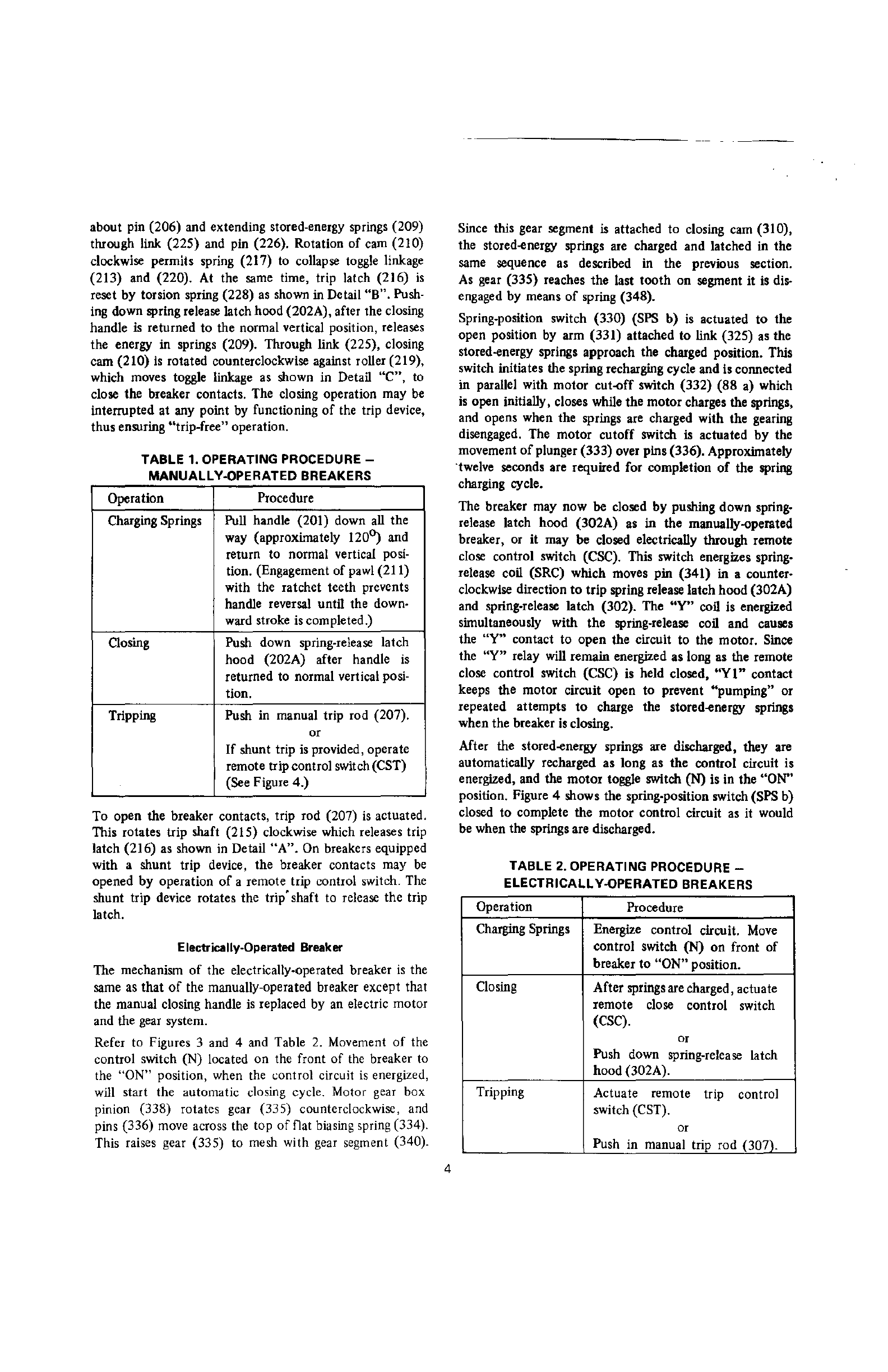
about pin (206) and extending stored-energy springs (209)
through link
(225)
and pin (226)_ Rotation of cam (210)
clockwise permits spring (217) to collapse toggle linkage
(213)
and (220)_ At the same time, trip latch (216)
is
reset
by
torsion spring (228)
as
shown in Detail
"B"_
Push-
ing down spring release latch hood (202A), after the closing
handle
is
returned to the normal vertical position, releases
the energy in springs (209)_ Through link (225), closing
cam
(210)
is
rotated counterclockwise against roller (219),
which moves toggle linkage
as
shown in Detail
"C",
to
close the breaker contacts. The closing operation may
be
interrupted at any point by functioning
of
the trip device,
thus ensuring "trip_free" operation.
TABLE 1. OPERATING
PROCEDURE-
MANUALL
V-OPERATED BREAKERS
Operation Procedure
Charging Springs Pull handle (201) down all the
way (approximately
120~
and
return to normal vertical posi-
tion. (Engagement
of
pawl (211)
with the ratchet teeth prevents
handle reversal until the down-
ward stroke is completed.)
Oosing Push down spring-release latch
hood (202A) after handle
is
returned to normal vertical posi-
tion.
Tripping Push in manual trip rod (207).
or
If
shunt trip
is
provided, operate
remote trip control switch (CST)
(See Figure 4.)
To
open the breaker contacts, trip rod (207)
is
actuated.
This rotates trip shaft (215) clockwise which releases trip
latch (216)
as
shown in Detail
"A".
On breakers equipped
with a shunt trip device, the breaker contacts may
be
opened
by
operation
of
a remote trip control switch. The
shunt trip device rotates the
trip'shaft
to release the trip
latch.
Electrically-Operated Broeker
The mechanism
of
the electrically-operated breaker
is
the
same
as
that
of
the manually-operated breaker except that
the manual closing handle
is
replaced by an electric motor
and the gear system.
Refer to Figures 3 and 4 and Table
2.
Movement
of
the
control switch (N) located on the front of the breaker to
the
"ON"
position,
when
the (';ontrol circuit
is
energized,
will
start
the
automatic
closing cycle. Motor gear
box
pinion (338) rotates gear (335) counterclockwise, and
pins (336) move across the top
of
!lat biasing spring (334).
This raises gear (335) to mesh with gear segment (340).
4
Since this gear segment
is
attached to closing cam (310),
the stored-energy springs are charged and latched in the
same sequence as described in the previous section_
As
gear (335) reaches the last
tooth
on segment it
is
dis-
engaged by means
of
spring (348)_
Spring-position switch (330) (SPS b)
is
actuated
to
the
open position by arm (331) attached to link (325)
as
the
stored-energy springs approach the charged position. This
switch initiates the spring recharging cycle and is connected
in parallel with motor cut-off switch (332)
(88
a) which
is
open initially, closes while the motor charges the springs,
and opens when the springs are charged with the gearing
disengaged. The motor cutoff switch is actuated
by
the
movement
of
plunger (333) over pins (336). Approximately
·twelve seconds are required for completion
of
the spring
charging cycle.
The breaker may now be closed
by
pushing down spring-
release latch hood (302A)
as
in the manually-operated
breaker, or it may be closed electrically through remote
close control switch (CSC). This switch energizes spring-
release coil (SRC) which moves pin (341) in a counter-
clockwise direction
to
trip spring release latch
hood
(302A)
and spring-release latch (302). The "Y" call is energized
simultaneously with the spring-release coil and causes
the "Y" contact to open the circuit to the motor_ Since
the "Y" relay will remain energized as long
as
the remote
close control switch (CSC)
is
held closed,
"YI"
contact
keeps the motor circuit open to prevent "pumping" or
repeated attempts
to
charge the stored-energy springs
when the breaker
is
closing.
After the stored-energy springs are discharged, they are
automatically recharged as long as the control circuit is
energized, and the
motor
toggle switch (N) is in the
"ON"
position. Figure 4 shows the spring-position switch (SPS b)
closed to complete the motor control circuit
as
it would
be when the springs are discharged.
TABLE 2. OPERATING PROCEDURE -
ELECTRICALLV-OPERATED BREAKERS
Operation Procedure
Charging Springs Energize control circuit.
Move
control switch (N)
on
front of
breaker to
"ON"
position.
Closing After springs are charged, actuate
remote close control switch
(CSC). or
Push down spring-release latch
hood (302A).
Tripping Actuate remote trip control
switch (CST). or
Push in manual trip rod (307).

,
/
•
ARM
............
• LINK
• PIN
.............
eTRIPROD
.SPRING
(X)I+)
SPRING
POSITION
SWITCH
,-i1
.....
LJ-\
331 REF
~.~--i--------
SWITCH
".9)..
__
.'
:
~~
BRACKET
\.
CLOSING
CAM
MOTOR
Cur·OFF
SWITCH
NUT
~~~NUT
FLAT
SPRING
GEAR
PINS
MOTOR GEAR-BOX
PINION
PLUNGER
EYE
END
Figure
3.
-Typical OperatingMechllnism -Electrically Operated Breaker
REF
NOTE:
SWITCHES
MOUNTED
ON
BRACKET
--
-----------
-----
- -
--
--
-r-"
-I·~---r;-------I~s-c----~
t~~
(X)(+)
_______________________
~
__
,
ee
SPS
'Y
t--'>"
I G I R
o b
'T2
~
S~
As
SUPPLY
M Y,
e":
Y 1
,T
-
f'
\IIJ>-
-Ti------Tcs.;----
-~'
*CS-T®:
nee
,x-
2
--
~PPLY:,
's
T
-
.~~+
IY)(-)
--7'
4
~
, ,
st'
61
v
:s
9
10
N S b r
3 b
•
AC
CONTROL
;,,;':'9:f
fir
r
4
,
~1
sf
v
~
9
10
DC
CONTROL
DVERCURRENT
STATIC
TRI P
DEVICE
WIRING
TRANSFORMERS
xt
'X2
Ixl2~211
"i'l>;ll
MAGNETIC
TRIP
COIL
o
2
2.
3
o 0 o 0 0 0 STATtC
TRIP
3 4 5 6 7 B
TERMINAL
BLOCK
Figure
4.
-Typical Wiring Diagram -Electrically Operated Breakers
5

Racking
Mechanism,
Drawout Interlock,
and
Lifting
Bar.
Cubicle-mounted breakers
of
the drawout type include
as
integral parts the mechanism to rack the breaker
in
and
out
of
the cubicle compartment, the drawout trip inter-
lock, and the drawout position markings_
72-440-010...01
RACKING
CLEVIS
DETAIL-IIA'•
RACKING
SCREW
RACKING
CLEVIS
,
TRIP
ROD
(ELECTRICALLY
OI'£R. BREAKERS)
CUBICLE
FIXED
PIN
TRIP
SHAFT
Refer to Figure
5_
Lifting bar (SOl) may be used to lift
the breaker when
it
is
being inserted
in
the cubicle_
With the breaker
in
position on the rails, the following
sequence should be used to rack the breaker into the fully
connected position.
LIFTING
BAR
INTERLOCK
SLIDE
---,
I.'
.""'e
••
CUBICLE
INTERLOCK INTERLOCK CAM
SIDE VIEW
Figure 5. -Typical Racking Mechanism and Drawout Interlock
6

CAUTION
On
electrically-operated breakers, be cenain that the
control switch on the front
of
the breaker
is
in
the
"OFF"
position.
I.
Push trip bar and lower the interlock slide
(502)
to
expose
racking screw (504). (Lowering the interlock slide will
also actuate trip rod
(506)
SO
that
a closed breaker will
be tripped.) While the interlock slide
is
in this position,
the
breaker
is
"trip·free"
and cannot be closed.
2. With the switchgear operating crank, rotate racking
screw
(504)
to move racking clevises (505)
to
the posi·
tion shown where they will engage with fixed pins (503)
in the cubicle.
3. The breaker should now be pushed along the rails to
the "DISCONNECTED" position. At the same time
the racking clevises (505) should be checked
to
see that
they
are in correct alignment with cubicle fixed pins
(503).
Counterclockwise rotation
of
the operating crank will
now rack the breakerintothe
"TEST"
and CONNECTED
·positions.
At
the
''TEST''
and
CONNECTED positions,
interlock
(508)
is
in its normal horizontal position.
By
removing operating crank
and
then raising interlock
slide (502), trip rod (506) returns
to
the extended posi·
tion permitting trip shaft
(507)
to reset and the breaker
may be operated.
Between
''TEST''
and CONNECTED positiQns, the cubicle
interlock cam
(509)
raises interlock (508)
to
hold trip
rod
(506)
and trip shaft
(507)
in the "trip·free" position
so that
the
breaker cannot
be
closed even
if
interlock
slide
(502)
is
raised. This
is
to
prevent movement
of
a
closed breaker into or
out
of
the CONNECTED position.
4.
To
withdraw the breaker from the CONNECTED position,
the procedure
is
the same except that the direction
of
rotation
of
the operating crank
is
clockwise.
5.
If
necessary
to
adjust racking screw stop (510) rotate
racking screw (504) until racking clevis (505) reaches
the
77
0 position
as
shown' (Detail
"A").
Position
stop (510) against crank (511) with
nut
(512).
CAUTION
To
avoid damage to the racking mechanism,
do
not
rotate the operating crank in the counterclockwise
direction
after
the breaker has reached the
fully
connected position.
Spring Discharge Mechanism
Description
and
Fu
netion
(See Figures 2 and 6.) When racking circuit breaker OUT
of
cubicle (see Racking Mechanism, Drawout Interlock.
7
and Lifting Bar, page
6)
the stored energy closing
springs
(209)
will automatically discharge prior to or when
circuit breaker reaches the DISCONNECT position.
This
is
accomplished by the following sequence:
1.
Lever (601) rotates clockwise during RACKOUT,
allowing roller
(602)
on
lever (601) to rotate
carn (603) counterclockwise.
2. Cam (603) moves rod
(604)
upward which in turn
rotates lever
(605)
clockwise.
3. Lever (605) in
turn
rotates spring release latch
(613)
clockWise allowing
the
storedenergy closing springs
(209)
to discharge.
4. When roller (602) strikes carn (603) and stored energy
springs discharge, cam (603) must snap back into reset
position prior to or when circuit breaker reaches the
DISCONNECT position.
Adjultmentl
If
adjustment becomes necessary
the
following procedure
will be required (see Figures
I,
2,
and
6):
1.
Remove cover
(126).
CAUTION
With cover removed and circuit breaker contacts
open, the circuitbreaker will CLOSE when the stored
energy springs
are
discharged automatically since
the
slide interlock is
not
inplace.
2.
Align scribed line
on
trunion
(606)
with center punch
mark (TEST position)
on
arm (607).
3. Remove cotter pin
(610,
remove washers (611),
remove rod
(604)
from cam (603). Adjust rod I (604),
by screwing into
or
out
of
yoke
(612)
until the nominal
.375 dimension
is
obtainedbetween the end
of
rod (604)
and inside
of
yoke (612). Insert rod (604) into
cam
(603),
replace washers
(611),
insert
cotter
pin (610) and bend.
4. Charge stored energy springs
(209)
and rotate racking
screw (222) in the clockwise direction (see Racking
Mechanism, Drawout Interlock, and Lifting Bar, page 6).
The stored energy closing springs should automatically
discharge (see caution note, above) prior
to
or when
circuit breaker reaches the DISCONNECT position.
Cam
(603)
must snap back
to
reset position as shown.
(See Step 4
of
Description and Function, above.)
5. If the stored energy closing springs DO NOT auto-
matically discharge as described in Step 4:
a)
Repeat Adjustments, Step 2.
b)
Readjust as necessary per Adjustments, Step 3 within
the prescribed tolerance limits
of
.375
:!:,.062.
6.
Repeat Adjustments, Step 4.

72-240-103-401
SET
SC~'EWr.o,i'\
NUT
j
-0-
SHAFT
---
(TEST POSITION)
ROLLER
DISCONNECT POSITION
Figure
6.
-SpringDischarge Mechanism
8
,
,
~
,
,
~
CAM
(RESET POSITION)
COTTER PIN
WASHER
LEVER
LATCH

<"\
•
-
MAINTENANCE
AND
ADJUSTMENTS
Maintenance
Occasional checking and cleaning
of
the breaker will pro-
mote long and trouble-free service. A periodic inspection
and servicing
at
intervals
of
six months or one year should
be
included in the maintenance routine. Circuit breakers
located in areas subject
to
acid fumes, cement dust, or
other abnormal conditions, require more frequent
ser-
vicing.
After a severe overload interruption, the breaker
should be inspected.
If
the circuit breaker
is
not operated during extended
periods, it should not remain
in
either the closed or open
position any longer than six months. Maintenance opening
and closing operations should be made to ensure freedom
of
movement
of
all parts.
A suggested procedure
to
follow during maintenance
inspections
is
given below.
I. De-energize the primary and control circuits.
2.
Rack cubicle-mounted breakers
of
the drawout type to
the disconnected position.
4. Remove breaker from cubicle.
5.
Remove arc chutes (117, Figure
I)
and examine for
burned, cracked
or
broken parts. To remove arc chutes,
proceed as follows (see Figure 5):
a.
Move
breaker
to
disconnect position.
b. Turn racking screw (504) until crank (511) IS m
vertical pOsition,
giving
maximum clearance between
screw and holding bar.
c. Remove wing nuts from holding bar.
d. Tilt top
of
holding bar toward back
of
breaker and
move
bar down.
NOTE
After inspection and before moving breaker to test
position,
turn
racking screw (504) until racking
clevis
(505) reaches its normal disengaged position.
6.
Wipe
the contacts with a clean'cloth saturated with a
non-toxic cleaning fluid.
7.
Replace badly burned or pitted contacts (see Contact
Replacement,
page
II).
8.
Wipe
all insulated parts with a clean cloth saturated
with a non·toxic cleaning fluid.
9. Bearing pins and other sliding or rotating surfaces should
be cleaned and then coated with a light film
of
grease
(see Lubrication, next paragraph).
10. Operate the breaker manually
in
maintenance closing
position (see Maintenance Closing, below)
to
check
latch and linkage movement.
9
II.
Check breaker adjustments (see Adjustments,
page
11).
Lubrication
Lubrication should be a part
of
the servicing procedure.
Needle bearings are packed with
grease
and should require
no further attention. Old grease should be removed from
bearing pins and other rotating or sliding surfaces, and
they should be wiped with a thin film
of
petroleum-oU·
base precision-equipment grease similar to
BEACON
P-290.
Greasing should be done with care because excess
grease
tends
to
collect foreign matter which in time may make
operation
sluggish
and may affect the dielectric strength
of
insulating members. Faces
of
main and arcing contacts
should not be lubricated. The rubbing surfaces
of
the main
contact fmgers and hinge contact fingers
are
lubricated
with micro
fme
dry graphite.
If
dust has accumulated,
dis-
assembly
is
necessary to relubrlcate these points (see
Contact Replacement,
page
II).
Maintenance
Closing
During inspection prior to installation and for routine
maintenance inspections, the breaker contacts may be
closed slowly
to
check clearances, contact adjustments, and
movement
of
links and latches. The manual closing handle
is
used for maintenance closing the breaker.
Electrically·operated breakers do not have a manual closing
handle,
but
a manual closing handle-carn assembly
is
available
as
a maintenance item. Figure 7 shows the main-
tenance closing handle being inserted in an electrically·
operated breaker after removal
of
the front cover from the
breaker.
When
the hole
in
the maintenance closing handle
assembly is aligned with the holes
in
the operating mech-
anism frarne, the pin which
is
attached
to
the chain
is
inserted. This pin holds the assembly
in
place and acts
as
a
pivot point for the earn.
After insertion
of
the maintenance closing handle assembly
on the electrically.operated breaker, the actual maintenance
closing operation
is
the
same
for both the electricaUy·
operated breaker and the manuaUy-operated breaker. Refer
to
Table 3 and Figure 7.
CAUTION
The
procedure
in
Tabl. 3 should
b.
used
for
main·
tenance closing
only
.

MAINTENANCE CLOSING H'ANOLI,
-;
:-
_______
J
(SEE
PAGE
9)
RELEASE LATCH
HOOD
____
~-
~
MAINTENANCE
CLOSING
HANDLE
ELECTRICALLY OPERATED BREAKERS
SEE
TABLE 3 a
FIG
2
{STEP
I
. STEP
TYPICAL MAINTENANCE
CL
OSI
NG
HANDLE
PROCEDURE
MA
N
UAL
TRI
PR
OD
Figure 7. - Maintenance Closi
ng
10
.,
~
.•
•
-

-.
TABLE 3. MAINTENANCE CLOSING
Operation Procedure
Closing Contacts
1.
Pull closing handle
DOWN
ALL THE
WAY
(approx·
imately
120~.
2. Place blade
of
screwdriver be·
tween hood and spring
reo
lease latch and hold it in
this position.
3. Slowly return handle
to
ver·
tical position.
(Contacts will close
to
arc-
ing contact touch position,
but
breaker will not close
completely.)
Opening Contacts Push in manual trip rod.
NOTE
Holding the spring release lateh down prevents the
stored-energy springs from propping in the charged
position. Thus, when the handle
is
slowly returned
to the normal vertical position, the energy in the
springs
is
slowly released against the closing handle
assembly cam face.
Adjustments
During maintenance inspections, the following items should
be checked to ensure that the original settings are main-
tained:
Trip-Latch Engagement
(Refer to Figure 2.) Trip latch (216) should have an engage-
ment
of
.062"
plus 0 minus
.015"
on trip shaft (215).
Measurement is made with the latch resting on the shaft in
the reset position. With this engagement, the trip shaft
must rotate between 10.50 and
ISO
to release the trip
latch.
Main Contact Make
(Refer to Figure 8.) Compression
of
contact fingers (817)
should be between
.093"
and .125". This
is
the difference
in the measurement from the breaker base to the
bottom
of
the finger contact surface when the breaker
is
open and the
measurement in the same place when the breaker
is
closed.
This is checked with a normal closing operation -not
maintenance closing. Adjustment is provided by positioning
screws (810) after loosening nuts (814). Counterclockwise
rotation
of
screws (810) increases compression. Care should
be
taken to retighten nuts (814) after adjustment.
If
it
is
desired
to
check
contact
pressure, a push-type spring scale
can
be
used to compress contact fingers (817) with the
11
breaker open. Contact pressure should be between
20
and
30
pounds.
Arcing Contact Make
(Refer to Figure 8.) With movable arcing contact in
anyone
phase touching the mating stationary contact when the
breaker
is
closed by the maintenance closing method (see
Table 3), the phase-te-phase variations should not exceed
.061
".
Adjustment may be made by positioning screws (810)
as in the preceding paragraph,
but
it is essential that the
maincontactcompression be maintained within the tolerance
of
.093" and .125". Arcing contact pressure can be checked
with the breaker contacts closed by pulling
both
contacts
at
the base
of
the arcing contact tip insert with a pull-type
spring scale until contacts part. The contact pressure should
be
between
70
and
80
pounds.
Electrically-Operated Breaker.
(Refer to Figures 3 and 4.)
I.
Motor-Cut-Off Switch and Spring-Position Switch
These switches are mounted
on
a common bracket which
is
set and roll-pinned in pOsition during production
testing.
If
replacement
is
required, the bracket must
be
pOSitioned so
that
when roll pins (336) in gear (335)
are
at the top position, they have moved plunger (333)
against the roller
of
motor cut-off switch (332) to shut
off the motor. As the springs are charged, arm (331)
must engage the roller
of
spring-pOsition switch (330).
Pilot holes are provided in the mounting bracket for
drilling and roll-pinning the replacement assembly in
the correct position.
2. Gear Disengagement
(Refer to Figure 3.) With the breaker closing cams (310)
in the horizontal position, adjust the tension
of
spring (348) by means
of
eye end (300) and nuts
(301, 304) until a dimension
of
2 3/8
!1/32
is
measured between spring loops. This dimension is
measured when gear (335) touches or meshes with gear
segment (340).
At
this point a force
of
5 1/2 to 7 Ibs
will
be
required to hold the gears in contact.
Contact Replacement
(Refer to Figure 8.) The contact structure consists
of
main
current carrying contacts and arcing contacts arranged
so
thatinitial contact make and final contact break
is
by means
of
the arcing contacts. The main contacts are not subject
to arcing. The actual contact surfaces are clad with an alloy
facing which greatly reduces mechanical wear and arc
erosion.
When
inspection
of
the alloy facing indicates that the con-
tacts should
be
replaced, it should be noted that hinge con-
tact fingers (820), main contact fingers (817) and arcing

72-340.()'21-401
CONTACT
FINGER
DETAIL-"A"
------
@
@
tKj tKj
0 0 0 0
IP<
:
>QJ
©¢"'5()
0 0 0 0
I
@
0 0
o 0
0
.187 DlA
CONTACT
ING
(J)
@
~ 0
0
SET
SCREW
WRENCH
DETAIL-"a"
BASE
SPRING
CLEVIS
SCREW
WASHER
PAN
SPACER-SEE
DETAIL--A-
I ARC RUNNER
Figure
8.
-Typical Panel Assembly
contacts (819) are spring loaded. Therefore, extreme care
must be exercised in removal and installation
of
any
of
the
contacts.
Main Contact Fingers
With the breaker contacts open and the stored-energy
springs discharged, main contact fingers (817) may be
reo
moved
by
loosening screws (823) enough to relieve the
compression
on
springs (822)
as
shown in Detail
"A".
There are two springs behind each fidger, and it
is
important
that they be positioned properly upon reinstallation.
If
difficulty is experienced in correctly positioning these
springs, the upper and lower primary disconnects (119,
Figure
I)
may be removed from each phase and the
breaker inverted to rest on the ends
of
connectors (824)
and (828).
After the contact fingers are replaced, connector (824)
should be positioned in the center
of
the slot
in
the molded
base to assure correct alignment
of
the primary disconnect
fmgers.
Stationary Arcing Contact
The stationary arcing contact
is
a
part
of
connector (824)
and may
be
replaced by proceeding
as
above. In this case.
12
screws (823) must
be
removed. However,
to
provide a
clearance for removal
of
connector (824), first insert a
.187" diameter rod
at
least
3"
long through the opening
in support (821)
as
shown in Detail "B". This
will
hold
hinge contact fmgers (820) in position to permit removal
of
pin (805).
It
may
be
necessary
to
compress contacts (820)
opposite arcing contacts
(8l9)
in order to insert the rod.
(As
an
aid in holding spacers (804) and (806)
in
their
correct positions, withdrawal
of
pin (805) can
be
followed
by the insertion
of
a shorter pilot pin
to
permit removal
of
the
complete movable contact assembly as a group from
support
(82l).)
The
pin
at the end
of
clevis (802) should
then
be
removed so
that
the complete movable contact
assembly can
be
positioned or removed to provide clearance
for removal
of
connector (824).
Hinge Contact Fingers
Hinge contact fingers (820) may
be
removed
as
follows:
Remove top screws
(826)
from support (82
I)
and
replace
them with two .250-20 screws at least
IS'
long. Remove
lower screws
(8l6)
and then gradually back
off
the
lS'·
screws
as
shown
in
Detail
"8".
to
relieve the loading from
springs (827). The hinge contact fingers can now
be
reo
moved.
Be
certain to replace the 1.5" long screws with the
original screws after replacement
of
the contact fingers.

in
position to permit removal
of
pin (803). After removal of
pin
(803). main contact (817) and arcing contact (820) can
be
positioned
so
that connector (829)
can
be removed.
Hinge Contact Finger.
Hinge contact fingers (814) may be removed
as
follows:
Remove top
screw
(827) from support (815) and replace it
with a 1/4·20 screw at least 1·1/2" long. Remove lower
screw (827) and then gradually back
off
the 1-1/2" screw
as shown
in
Detail
"B",
to relieve the loading from
springs (828). The hinge contact fingers can now
be
removed. To provide easier access
to
the
hinge
contact
fmgers, pin (803) may
be
removed after tbe loading
is
relieved from springs (828).
Moving Arcing
and
Main
Contact
Either moving arcing contact (820) or main contact (817)
or both may be removed and replaced as follows: Follow
the steps outlined
in
the above paragraph including removal
of pin (803) or
if
hinge contact fingers
are
not to
be
re-
placed, omit these steps and begin
by
placing a 3/16"
diameter rod
at
least 2" long through the opening
in
support (815) as shown
in
Detail "B". Remove pin (SOl)
and pin (S03)
if
these
have
not been removed previously.
The complete movable contact assembly may now
be
brought to a bench.
It
is
suggested
that
a
I/Z"
thick piece
of
wood or phenolic be placed upright in a
vise
and the open
slot in
clevis
(812) placed against
it
as
a rest. The. location
of
spacers (802), (S04) and (825) should
be
noted. To
minimize adjustment upon reassembly, the position
of
the
two screws (80S) relative to pin (818) should also
be
noted. Then the two elastic stop nuts (S21) should
be
loosened and screws (80S) backed
off
far enough to
remove them from pin(SIS).
CAUTION
Extreme care should be taken
to
hold
the assembly
firmly
to
retain spring guide (bID)
and
spring (809)
upon
removal
of
the
screws.
The moving arcing contact or the main contact may
now
be
easily replaced. The reverse procedure
is
followed for
re-
installation. Care should
be
taken to replace spacers (S02).
(804) and (S25) correctly. Check alignment and adjust-
ment
of
contacts upon reassembly.
Release
Magnet
When the static trip device senses a circuit condition
that
requires the circuit breaker to
open,
it produces an
output
that
is
fed
to the magnetic latch release device. This
device
then
causes the circuit breaker contacts to open and isolate
the circuit.
13
Mounted on the circuit breaker, the magnetic latch
release
is
held
in
a charged position by a permanent magnet.
It
contains a coil that
is
energized
by
the output
of
the static
trip device.
When
energized,
the
coil causes the magnetic
flux to shift to a
new
path, releasing the stored energy ofa
spring located
inside
the
magnetic latch
r~lease.
The spring
provides
the
energy to trip the breaker.
The
release
magnet
is
illustrated
in
Figure 9. During normal
operation. trip rod (901), which
is
attached to a spring
loaded armature inside the magnetic
release
latch cylinder,
cannot move due to a magnetic
field
set
up
by
permanent
magnet (902) which holds the internal armature against
plate (903) on the bottom of the magnetic release latch.
When
an
overload or fault condition exists, coil (904),
which
is
inside
on the bottom of the magnetic release latch.
is
energized
by
the static trip device creating a
flux
which
decreases the magnetic hold force on the spring loaded
internal armature allowing the armature to
be
forced
up-
ward due to the spring load, thereby allowing trip rod (901)
to
move
up against trip arm (905).
in
turn, tripping the
circuit breaker.
As
the breaker opens. coil (904) becomes
de-energized due to de-energization of the static trip
device, cam (906) rotates
arm
(907) forcing spring loaded
armature against plate (903) allowing trip rod (901) to
be
reset to the non·trip
pOSition.
If
the spring loaded armature does not reset during trip
operation
as
explained above, spacers (908) may
be
added
to
obtain positive reset
of
the armature.
If
adding spacers does not allow armature to be reset. th,
magnetic release latch should
be
replaced
(if
breaker
mech-
anism
is
not at fault).
NOTE
Do
not attempt to disassemble the magnetic release
latch as this
will
destroy the magnetic field
set
up by
the permanent magnet and
will
render
the
release
latch inoperative permanently.
When
replacing a magnetic release latch, the
coil
(904)
leads must be connected to the terminal block
of
the static
trip
in
the correct polarity relationship.
The black lead ofcoil (904) must
be
connected to terminal 7
(negative) and the red lead of
coil
(904) connected to
terminal 8 (positive) of the static trip device.
A clearance of .032" to .060"
shOUld
be
maintained
be-
tween the trip
arm
(905) and nut (909) with the circuit
breaker open, springs charged and trip
arm
(905) reset
by
the trip shaft. Adjustment
is
made by positioning nut (909)
while
holding trip rod (901).
When
the magnetic release latch
has
been replaced the
circuit breaker should
be
given
a
FUNCTION
TEST
to
ensure proper operation
of
all
components. Refer to
Allis-Chalmers Instruction Book 18X4392
for
the
procedures
of the FUNCTION TEST.

72·240-068-401
CAM POSITION
----~
(SREAKER
CLOSED)
CAM
POSITlON-_~
(BREAKER
OPEN)
SPACER
PLATE
TRIP
ARM
/
/
/
TRIP
ROD
CAUTiON
SEALED UNIT.
00
NOT DISASSEMBLE
NUT
TO
.060
'.
----,
RESET CAM
RESET ARM
COIL
Figure
9.
-Typical Release Magnet
FUSE
FUNCTIONS
Current
Limiting
Fuse
(See Figure 10.) The
C.L
fuse
(100\)
NEMA
Class
"J"
and
Class
"L"
have an interrupting rating
of
200,000 Amps
RMS
Symmetrical.
When replacement
is
required due to the
C.L
fuse inter·
rupting, replace only with a fuse
of
the same manufacturer
and rating
as
supplied with the circuit breaker. Fuses of
different manufactures may have
c~nsiderably
different
melting time·current characteristics and peak let·thru cur-
rents and, consequently, may not be completely inter-
changeable.
14
To remove the
C.L
fuse, remove bolts (1002) and as·
sociated hardware. Remove fuse.
To
replace the c.L. fuse,
reverse the above procedure.
Trigger
Fuse
(See Figure 10.) The trigger fuse (1003) and associated
trip mechanism has a dual function. The first function
is
to
trip the circuit breaker mechanically when the C.L. fuse
has interrupted.
The second function
is
to indicate which phase
C.L
fuse
has interrupted.

71·240·102-401
TRIP
ARM
!cL
l
FUSE
BOLTS
ARM
TRIGGER
FUSE
~.~.,.
LEVER
COVER
r--l~~~~~~:~
FUSE WIRED IN PARALLEL
WITH ASSOCIATED
C.L:
FUSE.
Figure
ZO.
-
Current
Limiting
and
Trigger
Fuse
The
plunger (1004) on top
of
the trigger fuse indicates
visually which phase C.L.
fuse
has interrupted.
The trigger fuses are wired in parallel with the C.L. fuse.
When
the C.L. fuse interrupts, its associated trigger
fuse
also
opens and releases a plunger
(l004)
which
is
operated
by a precompressed spring contained in the trigger
fuse
housing.
The plunger operates
arm
(l005)
which allows spring
loaded
lever
(1006) toengage circuit breaker trip arm (1007)
•
which trips the circuit breaker and holds the circuit breaker
in
the mechanical trip free position.
The circuit breaker will remain trip free (cannot be closed)
until the trigger
fuse
has been replaced and the associated
15
trip mechanism reset
lever
(I
ODS)
has been manually
reset (pushed in).
To
remove the trigger
fuse
remove strap
(l009),
remove
plastic cover (1010), then the trigger fuse.
To insert the trigger fuse, reverse the above procedure.
CAUTION
The
trigger fuse (T003) must be inserted
with
the
plunger11004) facing arm (1005).
The
.125 +
0-
.032
dimension
must
be
maintained.

CURRENT
TRANSFORMERS
There
are
a
number
of
tripping
tran~former
ratings
avail-
able, each with seven calibrated pickup settings (Table 4).
Figure
II
shows a typical breaker rating plate.
The current transformers on the upper connectors for
the
lA·6OQ circuit breaker are mounted with
the
polarity
marks facing breaker panel. .
Breaker Tripping
Type and XFMR
Frame
Rating
Size
tl A
LA·6oo
80
40
200
100
600
400
200
600
300
The
current
transformer
on
the
lower connector
is
mounted
with the polarity
mark
facing away from the breaker panel.
TABLE
4.
TRIP
RATING
TABLE -AMPERES
Ground Element
Long Time Element
Max
Calibrated Pick.Up
Calibrated Pick·Up Settings Cont
2~~~
B C D E F G
50
60
70
80
90
100 100
.
32
64
80
125
150 175
200
225
250 250
40
80
160
200
250
300
350
400
450
500
500
80
160
320
400
375
450
525
600
675
750
600
120
240
480
600
SERIAL
10.
Figure
11. - Typical Breaker RatingPillte
16

71·240-584-401
BRACKET 1203 1207 BRACKET 1204 SHIELD
~t:I~1
NG 1205
::-:
-
~~~CONTACT
1201
I
-t--
-,
_BLOCk
,
'I
i+
n
••
I
i.~,
,'
IO-DISCONNECT MOUNTING
lO-DISCONNECT
MOUNTING
TERMINAL I
TERMINAL
TAB
Figure
12. -
Typical
Secondary
Disconnects
The electrical attachments
are
wired to the terminals
of
a
secondary disconnect assembly which
is
mounted
on
the
left
side
of the breaker_
Two
blocks of ten terminals each
can be mounted on the breaker. The secondary disconnect
17
assembly
is
accessible from the front
of
the breaker and
aligns
with a stationary unit in the cubicle. The stationary
contact strips should
be
lucricated with a light film of
AERO
LUBRIPLATE which
is
furnished with the switch·
gear.
Other manuals for LA-1600
1
This manual suits for next models
1
Table of contents
Other Allis-Chalmers Circuit Breaker manuals

Allis-Chalmers
Allis-Chalmers MA-75B User manual

Allis-Chalmers
Allis-Chalmers MA-75 User manual

Allis-Chalmers
Allis-Chalmers LA-1600 User manual

Allis-Chalmers
Allis-Chalmers LA-600 User manual

Allis-Chalmers
Allis-Chalmers LA-600 User manual

Allis-Chalmers
Allis-Chalmers FB-500A-FC-750A User manual

Allis-Chalmers
Allis-Chalmers LA 3000 User manual

Allis-Chalmers
Allis-Chalmers LA-600 User manual

Allis-Chalmers
Allis-Chalmers LA-25 Installation manual


