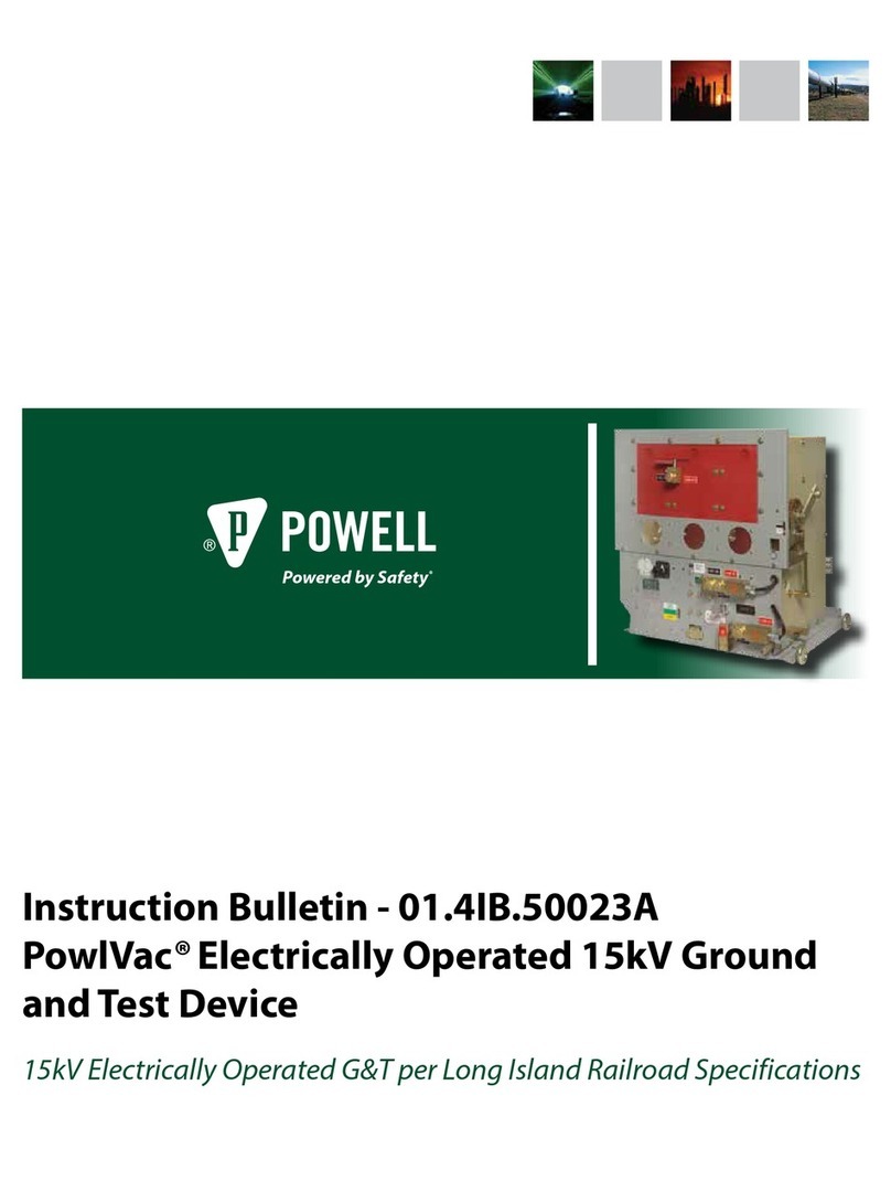
Powell IPS PowlVac IB-60202 CDR User manual

IB-60202 PowlVac®CDR
Vacuum Circuit Breaker
5kV & 15kV
1200A, 2000A, & 3000A
Powered by Safety®
Courtesy of store.ips.us

Powered by Safety®
IB-60202
Contact Information
Powell Electrical Systems, Inc.
www.powellind.com
info@powellind.com
Service Division
PO Box 12818
Houston, Texas 77217-2818
Tel: 713.944.6900
Fax: 713.948.4569
Courtesy of store.ips.us

Powered by Safety®
Signal Words
As stated in ANSI Z535.4-2002, § 4.13-4.13.3 the
signal word is a word that calls attention to the
safety sign and designates a degree or level of
hazard seriousness. The signal words for product
safety signs are “Danger”, “Warning”, and
“Caution”. These words are defined as:
DANGER indicates an imminently hazardous
situation which, if not avoided, will result in
death or serious injury.
DANGERDANGER
!
WARNING indicates a potentially hazardous
situation which, if not avoided, could result in
death or serious injury.
WARNINGWARNING
!
CAUTIONCAUTION
!
CAUTION indicates a potentially hazardous
situation which, if not avoided, may result in
minor or moderate injury.
Not stated in ANSI Z535.4-2002, § 4.13-4.13.3
as a signal word but used in this manual is
“IMPORTANT”. This is defined as:
IMPORTANT indicates a section of the manual
covering a non hazardous situation, but
one where Powell feels proper attention is
warranted.
IMPORTANTIMPORTANT
!
Qualified Person
For the purposes of this manual, a qualified person,
as stated in NFPA 70®, is one familiar with the
construction and operation of the equipment and
the hazards involved.
In addition to the above qualifications, one must
also be:
1. trained and authorized to energize,
deenergize, clear, ground, and tag circuits
and equipment in accordance with
established safety practices.
2. trained in the proper care and use of
personal protective equipment (PPE)
such as rubber gloves, hard hat, safety
glasses or face shields, flash clothing, etc.,
in accordance with established safety
practices.
3. trained in rendering first aid if necessary.
PowlVac®CDR Vacuum Circuit Breaker IB-60202
Courtesy of store.ips.us

Powered by Safety®i
IB-60202
Contents
Ch 1 General Information.................................................................................................1
A. Sc o p e ................................................................................................................................................................2
B. pu r p o S e .............................................................................................................................................................2
c. In S t r u c t I o n Bu l l e t I n S Av A I l A B l e el e c t r o n I c A l l y .....................................................................................................2
Ch 2 Safety ........................................................................................................................3
A. SA f e Wo r k co n d I t I o n .........................................................................................................................................3
B. SA f e t y Gu I d e l I n e S ...............................................................................................................................................3
c. Ge n e r A l .............................................................................................................................................................4
d. Sp e c I f I c ..............................................................................................................................................................4
e. X-rA y S ..............................................................................................................................................................5
f. SA f e t y lA B e l S .....................................................................................................................................................5
Ch 3 Equipment Description.............................................................................................6
A. Ge n e r A l .............................................................................................................................................................6
B. th e St o r e d en e r G y Me c h A n I S M ............................................................................................................................6
1) Mechanical Description.......................................................................................................................................................... 6
2) Electrical Description.............................................................................................................................................................16
c. rA c k I n G Me c h A n I S M ......................................................................................................................................... 17
1) General Description...............................................................................................................................................................17
2) Closed Door Racking Mechanism ......................................................................................................................................19
d. cI r c u I t Br e A k e r co M p A r t M e n t In t e r f A c e S ........................................................................................................... 19
1) Primary Disconnecting Devices..........................................................................................................................................19
2) Secondary Disconnecting Devices.....................................................................................................................................19
3) MOC (Mechanism-Operated Contact) Actuator ............................................................................................................20
4) TOC (Truck-Operated Contact) Actuator..........................................................................................................................20
5) Ground Connection ...............................................................................................................................................................20
6) Shutter Rollers.........................................................................................................................................................................20
7) Anti-Rollout Latch..................................................................................................................................................................20
e. vA c u u M In t e r r u p t e r S ....................................................................................................................................... 20
f. vA c u u M In t e r r u p t e r co n n e c t I o n ....................................................................................................................... 21
Ch 4 Installation..............................................................................................................22
A. re c e I v I n G ........................................................................................................................................................ 22
B. hA n d l I n G ........................................................................................................................................................ 22
c. St o r A G e .......................................................................................................................................................... 23
d. pl A c I n G t h e cI r c u I t Br e A k e r In t o Se r v I c e ............................................................................................................ 24
1) High Voltage Insulation Integrity .......................................................................................................................................24
2) Vacuum Integrity....................................................................................................................................................................25
3) Control Voltage Insulation Integrity..................................................................................................................................26
4) Mechanical Operation Check..............................................................................................................................................27
5) Electrical Operation Check...................................................................................................................................................28
6) Racking Mechanism Check..................................................................................................................................................28
Courtesy of store.ips.us

Powered by Safety®
ii
PowlVac®CDR Vacuum Circuit Breaker
IB-60202
Contents
e. In S e r t I n G t h e cI r c u I t Br e A k e r In t o t h e cI r c u I t Br e A k e r co M p A r t M e n t .................................................................... 29
1) Prior to Inserting the Circuit Breaker into the Circuit Breaker Compartment..........................................................30
2) Inserting the Circuit Breaker to the Test/Disconnected Position.................................................................................31
3) Inserting the Circuit Breaker to the Connected Position...............................................................................................32
f. re M o v I n G t h e cI r c u I t Br e A k e r fr o M t h e cI r c u I t Br e A k e r co M p A r t M e n t ................................................................. 34
1) Removing the Circuit Breaker from the Connected to the Test/Disconnected Position........................................34
2) Removing the Circuit Breaker from the Test/Disconnected Position out of the Circuit Breaker
Compartment .........................................................................................................................................................................34
3) Power Racking ........................................................................................................................................................................35
Ch 5 Maintenance...........................................................................................................36
A. Ge n e r A l de S c r I p t I o n ........................................................................................................................................ 36
1) Introduction.............................................................................................................................................................................36
2) Inspection and Cleaning ......................................................................................................................................................40
B. Me c h A n I S M Ar e A ............................................................................................................................................. 40
1) Mechanical Operation ..........................................................................................................................................................40
2) Lubrication...............................................................................................................................................................................41
3) Closing Spring Removal........................................................................................................................................................41
4) Slow Closing of Mechanism.................................................................................................................................................42
5) Mechanism Adjustments......................................................................................................................................................43
6) Electrical Operation...............................................................................................................................................................47
c. vA c u u M In t e r r u p t e r A n d co n t A c t Ar e A ............................................................................................................. 48
1) Vacuum Interrupter and Contact Erosion........................................................................................................................48
2) Vacuum Integrity....................................................................................................................................................................48
3) Mechanical Adjustment of Vacuum Interrupters ...........................................................................................................48
d. op t I o n A l MA I n t e n A n c e pr o c e d u r e S ................................................................................................................... 48
1) High Potential Tests ...............................................................................................................................................................48
2) Timing.......................................................................................................................................................................................49
3) Primary Resistance Check ....................................................................................................................................................49
Ch 6 Recommended Renewal Parts and Replacement Procedures ...............................50
A. or d e r I n G In S t r u c t I o n S ..................................................................................................................................... 50
B. re c o M M e n d e d re n e W A l pA r t S ........................................................................................................................... 50
c. re p l A c e M e n t pr o c e d u r e S .................................................................................................................................. 50
1) Vacuum Interrupter Assembly.............................................................................................................................................51
2) Sliding Contact Finger Assembly........................................................................................................................................55
3) Closing Coil Assembly ...........................................................................................................................................................55
4) Primary Shunt Trip Coil Assembly ......................................................................................................................................56
5) Secondary Shunt Trip Coil Assembly .................................................................................................................................56
6) Undervoltage Device Assembly..........................................................................................................................................57
7) Charging Motor Assembly ...................................................................................................................................................57
8) Anti-Pump Relay Assembly..................................................................................................................................................57
9) Latch Check Switch................................................................................................................................................................57
10) Motor Cutoff Switch Assembly............................................................................................................................................58
11) Auxiliary Switch ......................................................................................................................................................................58
12) Primary Disconnecting Device Spring Assembly............................................................................................................59
Courtesy of store.ips.us
Table of contents
Other Powell Circuit Breaker manuals

Powell
Powell PowlVac ARG 4 Series Training manual

Powell
Powell PowlVac ASD User manual

Powell
Powell PowlVac ARG 4 Series Training manual

Powell
Powell PowlVac 01.4IB.50032C User manual

Powell
Powell PowlVac 38 ARM 3000A 4 Series Training manual

Powell
Powell PowlVac IB-60201 User manual

Powell
Powell PowlVac IB-65020A CDR 27kV User manual

Powell
Powell POWLVAC 15PV63SASD User manual
Popular Circuit Breaker manuals by other brands

WEG
WEG FHU ACW125 installation instructions

TERASAKI
TERASAKI NHP TemBreak PRO P160 Series installation instructions

Siemens
Siemens Sentron 3VA9157-0PK1 Series operating instructions

hager
hager TS 303 User instruction

ETI
ETI EFI-4B Instructions for mounting

Gladiator
Gladiator GCB150 Installation instruction