Powell PowlVac 01.4IB.51051C User manual

01.4IB.51051C
PowlVac®Remote Racking Device Assembly
(51897G11)
For Use With PowlVac®CDR 5kV & 15kV Circuit Breakers
Powered by Safety®


Powered by Safety®
01.4IB.51051C
Signal Words
As stated in ANSI Z535.4-2007, the signal word is
a word that calls attention to the safety sign and
designates a degree or level of hazard seriousness.
The signal words for product safety signs are
“Danger”, “Warning”, “Caution” and "Notice".
These words are defined as:
DANGER indicates an imminently hazardous
situation which, if not avoided, will result in
death or serious injury.
!
DANGER
!
WARNING
WARNING indicates a potentially hazardous
situation which, if not avoided, could result in
death or serious injury.
!
CAUTION
CAUTION, used with the safety alert symbol,
indicates a hazardous situation which, if not
avoided, could result in minor or moderate
injury.
CAUTION, used without the safety alert
symbol, is used to address practices not
related to personal injury.
CAUTION
NOTICE
NOTICE is used to address practices not related
to personal injury.
Qualified Person
For the purposes of this manual, a qualified
person, as stated in NFPA 70E®, is one who has
skills and knowledge related to the construction
and operation of the electrical equipment and
installations and has received safety training to
recognize and avoid the hazards involved. In
addition to the above qualifications, one must also
be:
1. trained and authorized to energize,
deenergize, clear, ground, and tag circuits
and equipment in accordance with
established safety practices.
2. trained in the proper care and use of
personal protective equipment (PPE)
such as rubber gloves, hard hat, safety
glasses or face shields, flash clothing, etc.,
in accordance with established safety
practices.
3. trained in rendering first aid if necessary.

Powered by Safety®
PowlVac®Remote Racking Device Assembly
for PowlVac® CDR 5kV & 15kV Circuit Breakers
01.4IB.51051C
This page is intentionally left blank.

Powered by Safety®i
01.4IB.51051C
Ch 1 General Information ................................................................................................1
A. Scope ...............................................................................................................................................................2
B. purpoSe ............................................................................................................................................................2
c. InStructIon BulletInS AvAIlABle electronIcAlly ....................................................................................................2
Ch 2 Safety .......................................................................................................................3
A. SAfe Work condItIon .........................................................................................................................................3
B. SAfety GuIdelIneS ...............................................................................................................................................3
c. GenerAl ............................................................................................................................................................3
d. SAfety lABelS ....................................................................................................................................................4
Ch 3 Equipment Description ............................................................................................5
A. GenerAl ............................................................................................................................................................5
B. Motor control Box ..........................................................................................................................................5
c. reMote rAckInG devIce .......................................................................................................................................5
d. reMote rAckInG operAtIon .................................................................................................................................6
Ch 4 Installation ...............................................................................................................9
A. receIvInG ...........................................................................................................................................................9
B. HAndlInG ..........................................................................................................................................................9
c. StorAGe ............................................................................................................................................................9
d. prepArAtIon ................................................................................................................................................... 10
1) Support Lock Pin, Support Hanger, and Installation Template ..................................................................................10
2) Testing and Inspection .........................................................................................................................................................10
3) Remote Racking Device Inspection ...................................................................................................................................10
Ch 5 Operation ...............................................................................................................11
A. InStAllInG And operAtInG tHe reMote rAckInG devIce for rAckInG In................................................................... 11
1) Installing the Remote Racking Device for Circuit Breaker Racking In .......................................................................11
2) Performing Circuit Breaker Racking In .............................................................................................................................14
B. InStAllInG And operAtInG tHe reMote rAckInG devIce for rAckInG out ................................................................ 15
1) Installing the Remote Racking Device for Circuit Breaker Racking Out ...................................................................15
2) Performing Circuit Breaker Racking Out ..........................................................................................................................16
c. unInStAllInG tHe reMote rAckInG devIce ........................................................................................................... 17
Ch 6 Maintenance ..........................................................................................................18
A. GenerAl ......................................................................................................................................................... 18
B. InSpectIon And cleAnInG .................................................................................................................................. 18
c. luBrIcAtIon .................................................................................................................................................... 18
Ch 7 Recommended Renewal Parts ...............................................................................19
A. orderInG InStructIonS ..................................................................................................................................... 19
Contents

Powered by Safety®
ii
01.4IB.51051C
PowlVac®Remote Racking Device Assembly
for PowlVac® CDR 5kV & 15kV Circuit Breakers
Tables
Table A Renewal Parts .....................................................................................................19
Figures
Figure 1 Remote Racking Device Assembly .................................................................5
Figure 2 Motor Control Box ..........................................................................................5
Figure 3 Remote Racking Device (Receptacle Side) .....................................................6
Figure 4 Remote Racking Device (Lock Pin Side) .........................................................6
Figure 5 Switchgear Compartment Door ....................................................................7
Figure 6 Circuit Breaker Inside Switchgear Compartment ..........................................8
Figure 7 Insert the Motor Control Box Cable Plug .....................................................12
Figure 8 Unlatch the Racking Device Spring Lock Pin ...............................................13
Figure 9 Insert the Drive Socket into the Racking Shaft Access Opening .................13
Figure 10 Push Down the Support Latch .....................................................................13
Figure 11 Turn the Spring Lock Pin to Secure the Racking Device
on the Support Lock Pin ...............................................................................13
Figure 12 Lift the Slide Assembly and Engage the Racking Device
Support Hanger ...........................................................................................14
Figure 13 Turn the Adjustment Knob to Engage the Racking Shaft
with the Drive Socket ...................................................................................14
Figure 14 Operate Motor Control Box .........................................................................15
Powered by Safety®1
General Information
01.4IB.51051C
Ch 1 General Information
!
WARNING
The equipment described in this document may contain high voltages and currents which can
cause death or serious injury.
The equipment is designed for use, installation, and maintenance by knowledgeable users of such
equipment having experience and training in the field of high voltage electricity. This document and all
other documentation shall be fully read, understood, and all warnings and cautions shall be abided by. If
there are any discrepancies or questions, the user shall contact Powell immediately at 1.800.480.7273.
!
WARNING
Prior to adjustments, servicing, maintenance, or any act requiring the operator to make physical
contact with the equipment, the power source must be disconnected and the equipment grounded.
Failure to do so may result in death or serious injury.
NOTICE
The information in this instruction bulletin is not intended to explain all details or variations of the
Powell equipment, nor to provide for every possible contingency or hazard to be met in connection
with installation, testing, operation, and maintenance of the equipment. For additional
information and instructions for particular problems, which are not presented sufficiently for the
user’s purposes, contact Powell at 1.800.480.7273.
Powell reserves the right to discontinue and to change specifications at any time without incurring
any obligation to incorporate new features in products previously sold.
NOTICE
Powered by Safety®
2General Information
01.4IB.51051C
PowlVac®Remote Racking Device Assembly
for PowlVac® CDR 5kV & 15kV Circuit Breakers
A. Scope
The information in this instruction bulletin
describes the following PowlVac®Remote
Racking Device and components for use
with PowlVac CDR 5kV & 15kV vacuum circuit
breakers:
• 51897G11 - Remote Racking Device and
Motor Control Box (complete assembly)
• 51899G10 - Remote Racking Device
• 51895G01 - Motor Control Box
B. purpoSe
The information in this instruction bulletin is
intended to provide information required to
properly operate and maintain the
PowlVac Remote Racking Device and
components described in Ch 1 General
Information, A. Scope.
This instruction bulletin provides:
1. Safety guidelines
2. General descriptions of the operation
and maintenance of the PowlVac Remote
Racking Device and components
3. Instructions for installation
4. Illustrations, photographs, and description
of the equipment described in
Ch 1 General Information, A. Scope
The illustrations and photos in this document
are provided as general information to aid in
showing component locations only.
All illustrations and photos are shown using
deenergized equipment.
Follow the appropriate safety precautions
while handling any of the equipment. Failure
to do so may result in death or serious injury.
!
WARNING
To the extent required, the products described
herein meet the applicable ANSI, IEEE, and
NEMA Standards; however, no such assurance
is given with respect to local codes and
ordinances which may vary greatly.
c. InStructIon BulletInS AvAIlABle electronIcAlly
Changes to the instruction bulletin may be
implemented at any time and without notice.
Go to powellind.com to ensure use of the current
instruction bulletin for Powell equipment.
NOTICE
To contact the Powell Service Division call
1.800.480.7273 or 713.944.6900, or email
For specific questions or comments pertaining
to this instruction bulletin email
documents@powellind.com with the Instruction
Bulletin number in the subject line.

Powered by Safety®3
Safety
01.4IB.51051C
Ch 2 Safety
A. SAfe Work condItIon
The information in Section A is quoted from
NFPA 70E 2012 - Article 120, 120.1 Establishing an
Electrically Safe Work Condition.
120.1 Process of Achieving an Electrically Safe
Work Condition
1. Determine all possible sources of electrical
supply to the specific equipment. Check
applicable up-to-date drawings, diagrams,
and identification tags.
2. After properly interrupting the load current,
OPEN the disconnecting device(s) for each
source.
3. Wherever possible, visually verify that all
blades of the disconnecting devices are
fully OPEN or that drawout type circuit
breakers are withdrawn to the fully
disconnected position.
4. Apply lockout/tagout devices in accordance
with a documented and established policy.
5. Use an adequately rated voltage detector
to test each phase conductor or circuit part
to verify they are deenergized. Test each
phase conductor or circuit part both
phase-to-phase, and phase-to-ground.
Before and after each test, determine
that the voltage detector is operating
satisfactorily.
Informational Note: See ANSI/ISA-61010-1
(82.02.01)/UL 61010-1, Safety Requirements
for Electrical Equipment for Measurement,
Control, and Laboratory Use - Part 1: General
Requirements, for rating and design
requirements for voltage measurement
and test instruments intended for use on
electrical systems 1000 V and below.
6. Where the possibility of induced voltages
or stored electrical energy exists, ground
the phase conductors or circuit parts
before touching them. Where it could be
reasonably anticipated that the conductors
or circuit parts being deenergized
could contact other exposed energized
conductors or circuit parts, apply ground
connecting devices rated for the available
fault duty.
B. SAfety GuIdelIneS
Each user has the responsibility to instruct
and supervise all personnel associated with
usage, installation, operation, and maintenance
of this equipment on all safety procedures.
Furthermore, each user has the responsibility of
establishing a safety program for each type of
equipment encountered.
The safety rules in this instruction bulletin are
not intended to be a complete safety program.
The rules are intended to cover only some of the
important aspects of personnel safety related to
PowlVac® Remote Racking Device Assemblies.
c. GenerAl
1. Only supervised and qualified personnel
trained in the usage, installation, operation,
and maintenance of the circuit breaker shall
be allowed to work on this equipment. It
is mandatory that this instruction bulletin,
any supplements, and service advisories be
studied, understood, and followed.
2. Maintenance programs must be consistent
with both customer experience and
manufacturer’s recommendations,
including service advisories and instruction
bulletin(s). A well planned and executed
routine maintenance program is essential
for reliability and safety.

Powered by Safety®
4Safety
01.4IB.51051C
PowlVac®Remote Racking Device Assembly
for PowlVac® CDR 5kV & 15kV Circuit Breakers
3. Service conditions and applications shall
also be considered in the development of
safety programs. Variables include ambient
temperature; humidity; actual continuous
current; thermal cycling; number of
operations; interrupting duty; and any
adverse local conditions including excessive
dust, ash, corrosive atmosphere, vermin
and insect infestations.
d. SAfety lABelS
Warning and Caution labels are located in
various places. Do NOT remove or deface any
of these warning/caution labels.
NOTICE
Powered by Safety®5
Equipment Description
01.4IB.51051C
Ch 3 Equipment Description
A. GenerAl
The PowlVac® Remote Racking Device
Assembly is an accessory which enables
circuit breakers to be racked into and out of
switchgear from a distance. The assembly
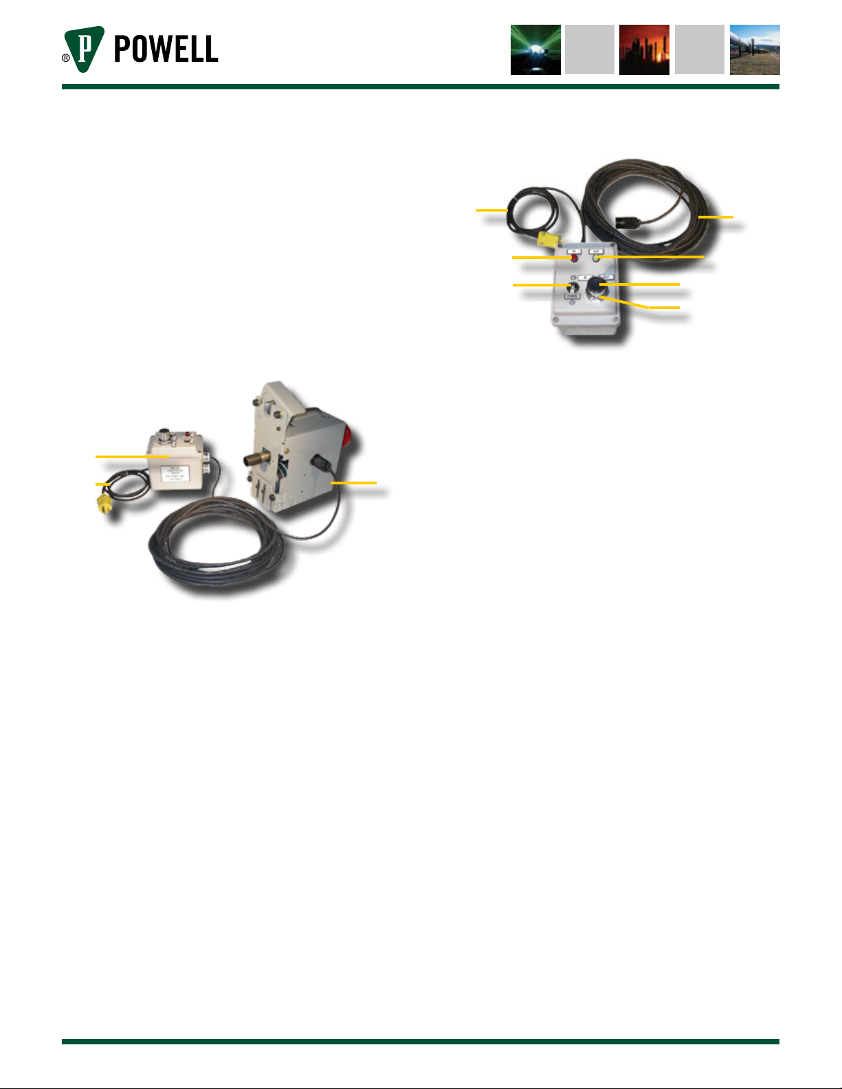
consists of a motor control box (Figure 1, a) and
remote racking device (Figure 1, b).
Figure 1 Remote Racking Device Assembly
a. Motor Control Box
b. Remote Racking Device
a
b
B. Motor control Box
The motor control box (Figure 2) supplies power
enables the selection of operating modes for
the remote racking device. The motor control
box has a 50 foot long cord (Figure 2, b) with a
plug that is inserted into the remote racking
device twist lock receptacle (Figure 3, f). The
length of cord enables the user to move to a
safe distance from the circuit breaker during
racking in and racking out procedures. The
motor control box power supply cord is
6’ long and plugs into a 110VAC 15A outlet
(Figure 2, a).
Figure 2 Motor Control Box
a. Power Supply Cord
b. Control Box Cord
c. “IN” Indicator Light
d. “OUT” Indicator Light
e. Power Switch
f. Push Button
g. IN/OUT Selector Switch
ab
ef
g
cd
c. reMote rAckInG devIce
The remote racking device (Figure 1, b) installs
on the switchgear compartment door. The
racking device support latch (Figure 3, a)
attaches to a lock pin (Figure 10, b) installed
on the compartment door. The racking
device drive socket (Figure 3, e) engages the
circuit breaker racking mechanism through
the compartment door racking shaft access
opening (Figure 5, d). After the racking device
is installed, the adjustment knob (Figure 4, b)
must be turned until the racking device drive
socket engages with the circuit breaker racking
shaft.
When the racking device is connected to the
motor control box and energized, the drive
socket operates the circuit breaker racking
shaft (Figure 6, b) during racking in and racking
out procedures.

Powered by Safety®
6Equipment Description
01.4IB.51051C
PowlVac®Remote Racking Device Assembly
for PowlVac® CDR 5kV & 15kV Circuit Breakers
Figure 3 Remote Racking Device (Receptacle
Side)
a. Support Latch
b. Recessed Bumpers
c. Handle
d. Drive Shaft and Spring
e. Drive Socket
f. Twist-Lock Receptacle
g. Front Plate
h. Slide Assembly
a
bc
d
ef
g
h
Figure 4 Remote Racking Device (Lock Pin
Side)
b
a
a. Latch Pin Lock
b. Adjustment Knob
d. reMote rAckInG operAtIon
Do NOT work on an energized circuit breaker.
Follow circuit breaker safety guidelines and
operating instructions provided in the specific
circuit breaker instruction bulletin.
!
WARNING
Attaching and operating the remote racking
device can be accomplished by one person.
When circuit breaker racking is required,
the remote racking device engages the
circuit breaker racking shaft through the
compartment door racking shaft access
opening (Figure 5, d). The racking device is
operated by the motor control box.
Powered by Safety®7
Equipment Description
01.4IB.51051C
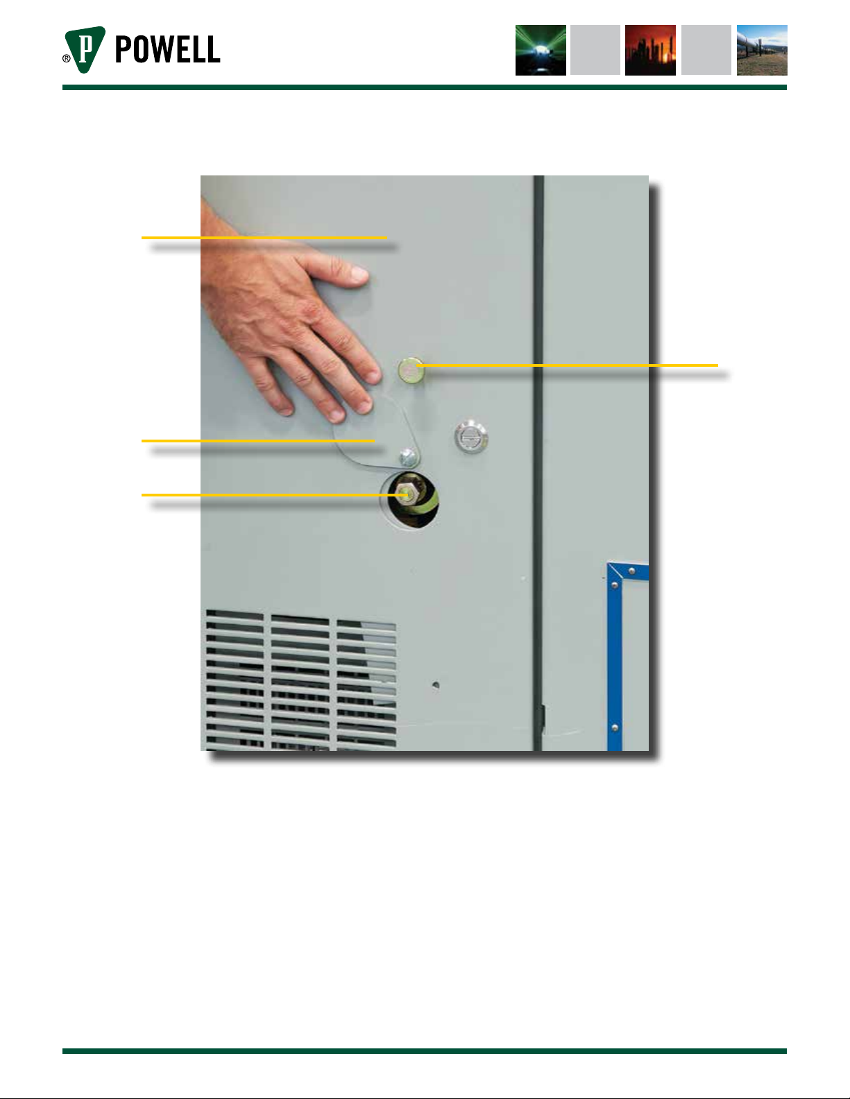
Figure 5 Switchgear Compartment Door
a
c
b
d
a. Compartment Door
b. Support Lock Pin
c. Circuit Breaker Racking Shaft Access Cover (Teardrop)
d. Circuit Breaker Racking Shaft

Powered by Safety®
8Equipment Description
01.4IB.51051C
PowlVac®Remote Racking Device Assembly
for PowlVac® CDR 5kV & 15kV Circuit Breakers
Figure 6 Circuit Breaker Inside Switchgear
Compartment
a. Circuit Breaker in Compartment
b. Circuit Breaker Racking Shaft
c. Secondary Disconnect Receptacle
d. Anti-Rollout Latch
e. Compartment Floor
a
e
c
d
b
Powered by Safety®9
Installation
01.4IB.51051C
Ch 4 Installation
A. receIvInG
Upon receipt, remove any shipping material
and inspect the remote racking device for
damage that may have occurred during
shipment. If damage is found or suspected, file
all claims immediately with the transportation
company and notify the nearest Powell
representative. Check the equipment received
against the shipping documents to ensure
receipt of the complete shipment.
B. HAndlInG
The remote racking device weighs 20 lbs.
and the motor control box assembly weighs
5 lbs. The preferred method for moving the
remote racking device and motor control box
is to place them securely on a hand operated
shop cart. When handling the remote racking
device, personnel should securely grasp the
device by its handle during movement and
installation to avoid possible personal injury or
damage to the remote racking device. Avoid
dropping or hitting the remote racking device
with hard objects.
Protect the motor control box and the remote
racking device from moisture. Failure to do so
may cause damage to the equipment.
!
CAUTION
Do NOT handle or carry the remote racking
device by the power cords. Damage to the
power connections may cause an electrical
short. The power cords should be inspected
for any signs of damage before each use.
!
CAUTION
Do not attempt to work with a remote racking
device and motor control box if the electrical
cords are damaged or if the devices have
become wet. Using electrical equipment in
or around water may cause electric shock
and may result in injury to personnel and/or
damage to equipment.
!
WARNING
c. StorAGe
The remote racking device and motor control
box are accessories that are not normally in
continuous service. These accessories should
be stored properly so that they will be available
when needed. The following precautions
must be taken to ensure proper storage of the
remote racking device and motor control box.
1. DO NOT store the remote racking device
and motor control box in the switchgear
compartment.
2. The remote racking device and motor
control box should be carefully protected
against condensation. The device should
be stored in a warm, dry room of moderate
temperature, such as 40 - 100°F. Since the
remote racking device and motor control
box are to be energized during use, they
must be kept completely dry to avoid
accidental electric shock to personnel
and/or damage to the equipment.
3. Store the remote racking device and motor
control box in a clean location, free from
corrosive gasses or fumes. Particular care
should be taken to protect the devices
from moisture and cement dust, as this
combination has a very corrosive effect on
many parts.

Powered by Safety®
10 Installation
01.4IB.51051C
PowlVac®Remote Racking Device Assembly
for PowlVac® CDR 5kV & 15kV Circuit Breakers
4. Apply A-grease on the drive shaft, under
the spring, to prevent corrosion and help
ensure proper operation.
5. If the remote racking device and motor
control box are stored for any length of
time, they should be inspected periodically
for corrosion and to ensure they are in good
mechanical condition.
d. prepArAtIon
Prior to using the Remote Racking Device,
refer to the Instruction Bulletin supplied with
the circuit breaker for complete instructions
on inserting and removing the circuit breaker
in to or out of the compartment.
CAUTION
1) Support Lock Pin, Support Hanger, and
Installation Template
Note: The circuit breaker must be removed
from service when the support lock
pin is installed.
The lock pin and support hanger must be
installed to support the remote racking
device on the compartment door.
A template for placing the support hanger
in the correct location is available. Refer to
Table A, Renewal Parts.
When installed, the racking device support
latch fastens onto the support lock pin, and
the slide assembly engages the support
hanger. The position of the racking device
enables the drive socket to engage the
circuit breaker racking shaft through the
access door to perform racking procedures.
To install the lock pin and support hanger,
follow directions accompanying the parts
order. For information on ordering the
support lock pin, support hanger, and
template, See Ch 7 Recommended Renewal
Parts.
2) Testing and Inspection
a. Electrical Operation Check
To pretest the equipment, insert the
50’ cord from the box into the racking
device locking receptacle. Then insert
the motor control box power supply
cord into a 110VAC 15A receptacle, and
operate the box on the racking in and
racking out settings while the device is
not installed on the circuit breaker or
compartment door.
3) Remote Racking Device Inspection
a. Inspect the remote racking device
for proper lubrication, signs of wear,
or damage. If plugs and wiring are
damaged, return the equipment to
Powell for repair.
b. Inspect the switchgear compartment
to ensure that it is clean and clear of
debris that might interfere with circuit
breaker racking and travel within the
compartment.
Powered by Safety®11
Operation
01.4IB.51051C
Ch 5 Operation
The instructions in this section are intended
to explain procedures for using the remote
racking device and the motor control box. For
circuit breaker handling, insertion, and removal
procedures, review the instruction bulletin
specific to the circuit breaker in use.
Do NOT work on an energized circuit breaker.
Follow circuit breaker safety guidelines and
operating instructions provided in the specific
circuit breaker instruction bulletin.
!
WARNING
A. InStAllInG And operAtInG tHe reMote rAckInG
devIce for rAckInG In
Before installing any circuit breaker into a
compartment, the user MUST verify that the
circuit breaker rating meets the metal-clad
switchgear rating.
!
CAUTION
This section describes procedures for installing
and operating the remote racking device for
racking IN. For racking OUT procedures, refer
to Ch 5 Operation, B. Installing and Operating the
Remote Racking Device for Racking Out.
1) Installing the Remote Racking Device for
Circuit Breaker Racking In
Prior to inserting the circuit breaker into the
circuit breaker compartment, ensure that the
control circuits are deenergized.
!
CAUTION
Prior to inserting the circuit breaker into the
circuit breaker compartment, ensure that the
circuit breaker is OPEN and the mechanism is
discharged.
!
CAUTION
1. Ensure the remote racking device
support lock pin (Figure 10, b) and the
support hanger (Figure 9, d) are installed
on the switchgear compartment door.
See Ch 4 Installation, D. Preparation,
1) Support Lock Pin, Support Hanger, and
Installation Template.
2. Ensure the switchgear compartment
control circuit is deenergized.
3. Move the circuit breaker to the
required switchgear location. Open the
compartment door and push the circuit
breaker into the compartment until the
anti-rollout latch (Figure 6, d) engages
the switchgear rollout stop block.
4. Insert the switchgear secondary
disconnect device into the circuit
breaker secondary disconnect
receptacle (Figure 6, c).
5a. For non-arc resistant switchgear,
perform the following steps:
• Assemble the racking mechanism
retainer assembly to the circuit
breaker compartment.
• Secure the racking drive shaft
extension in place by placing the
shaft retainer holder into the shaft
retainer anchor, then lock the
racking drive shaft extension in
place using the wing nut.
5b. For arc resistant switchgear, close and
latch the compartment door.

Powered by Safety®
12 Operation
01.4IB.51051C
PowlVac®Remote Racking Device Assembly
for PowlVac® CDR 5kV & 15kV Circuit Breakers
6. On the compartment door, rotate the
teardrop shaped racking shaft access
cover (Figure 5, c) clockwise to access
the opening.
7. To prepare the remote racking device
for operation, insert the plug of the
motor control box cord into the remote
racking device twist-lock receptacle
(Figure 7). Turn the plug / turn
clockwise to lock the plug in
the receptacle.
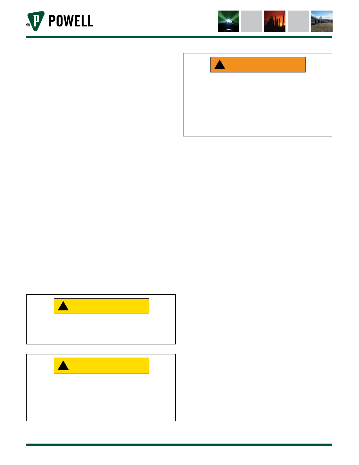
8. Unlatch the racking device spring lock
pin (Figure 8).
9. Grasp the remote racking device by the
top handle with the drive socket toward
the circuit breaker (Figure 9, a). Insert
the drive socket into the racking shaft
access opening until the socket engages
the circuit breaker racking shaft. With
the drive socket in place, position the
racking device support latch
(Figure 10, a) onto the support lock pin
(Figure 10, b).
10. Push down the top of the racking device
support latch to close the latch
(Figure 10, a).
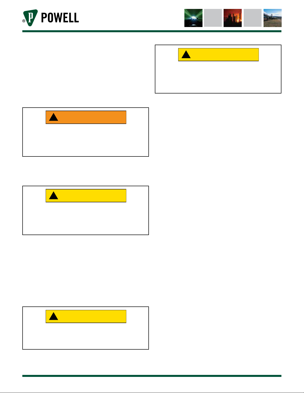
11. Turn the spring lock pin to the lock
position to secure the remote racking
device to the support lock pin
(Figure 11, a).
To avoid damage to equipment, and ensure
proper racking operation, the circuit breaker
racking mechanism must be engaged by the
racking socket before the remote racking
device is operated. For proper operation, the
racking device must be held securely by the
support lock pin and the hanger support.
CAUTION
12. With the racking device locked onto
the support lock pin, raise the racking
device slide assembly. Position
the racking device close to the
compartment door, and lower the slide
assembly to engage the racking device
support hanger (Figure 12).
13. With the racking device installed on the
compartment door, turn the adjustment
knob until it engages the drive socket
with the circuit breaker racking shaft
(Figure 13, a).
14. Physically move the motor control box
to a distant area to operate the remote
racking device.
The remote racking device is positioned
and ready to be energized for racking the
circuit breaker into the switchgear.
Figure 7 Insert the Motor Control Box Cable
Plug
a
b
a. Locking Receptacle
b. Motor Control Box Power Cable Plug

Powered by Safety®13
Operation
01.4IB.51051C
Figure 8 Unlatch the Racking Device Spring
Lock Pin
Figure 9 Insert the Drive Socket into the
Racking Shaft Access Opening
d
b
c
a
a. Drive Socket
b. Circuit Breaker Racking Shaft Access
c. Sliding Support
d. Support Hanger
Figure 10 Push Down the Support Latch
a
b
a. Support Latch
b. Support Lock Pin
Figure 11 Turn the Spring Lock Pin to Secure
the Racking Device on the Support
Lock Pin
a
a. Spring Lock Pin
Powered by Safety®
14 Operation
01.4IB.51051C
PowlVac®Remote Racking Device Assembly
for PowlVac® CDR 5kV & 15kV Circuit Breakers
Figure 12 Lift the Slide Assembly and Engage
the Racking Device Support Hanger
a
a. Slide Assembly Support
Figure 13 Turn the Adjustment Knob to Engage
the Racking Shaft with the Drive
Socket
a
a. Adjustment Knob
2) Performing Circuit Breaker Racking In
Before racking in a circuit breaker, ensure
the remote racking device is installed
properly, refer to Ch 5 Operation,
A. Installing and Operating the Remote
Racking Device for Racking In, 1) Installing
the Remote Racking Device for Circuit Breaker
Racking In.
1. Plug the motor control box power cord
into a 110VAC 15A receptacle.
2. On the motor control box, move the
power switch to the ON position
(Figure 14, d).
3. On the motor control box, turn the
selector switch to IN (Figure 14, c).
4. Depress the black push button on the
selector switch (Figure 14, e). The red
IN indicator lamp will illuminate. The
remote racking device will begin to rack
in the circuit breaker and will vibrate
slightly.
5. When the circuit breaker is fully racked
in, the remote racking device’s torque
limiter will begin to slip and there will
be a clear clicking sound along with a
vibration of the racking device. At this
point, release the push button.
Do not continue to rack in. If done, it may
cause damage to the equipment.
!
CAUTION
6. On the motor control box, move the
power switch to the OFF position.
7. Unplug the motor control box power
cord from the 110VAC 15A electric
receptacle when the racking in
procedure is successfully completed.
Note: To uninstall the remote racking device,
see Ch 5 Operation, C. Uninstalling the
Remote Racking Device.
Table of contents


