Power-Blox PBX-200 PB User manual

Swarm-enabled Solar Battery System
Installation and Operating instructions
PBX-200 PB (230 V, 200 W, 1.2 kWh AGM Battery)
PBX-200 Li (230 V, 200 W, 1.2 kWh Li-ion Battery)
EN
2017-03-13

Installation and Operating Instructions PBX-200 PB / Li page 2
Table of Contents
1!GENERAL(SAFETY(INSTRUCTIONS(...................................................................................................................(3!
2!SCOPE(OF(DELIVERY(......................................................................................................................................(4!
3!INTENDED(USE(..............................................................................................................................................(5!
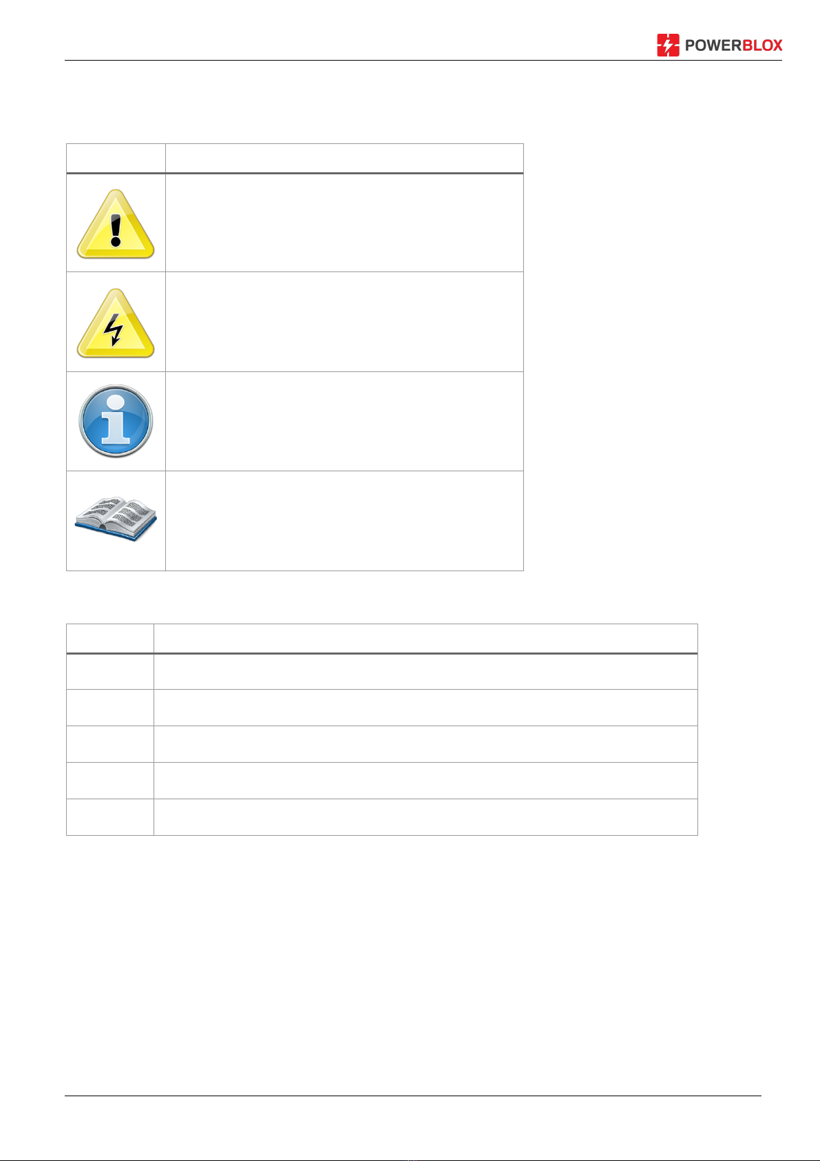
4!MARKINGS(....................................................................................................................................................(6!
4.1!SYMBOLS!FOR!WARNINGS!AND!NOTES!...................................................................................................................!6!
4.2!SIGNAL!WORDS!.................................................................................................................................................!6!
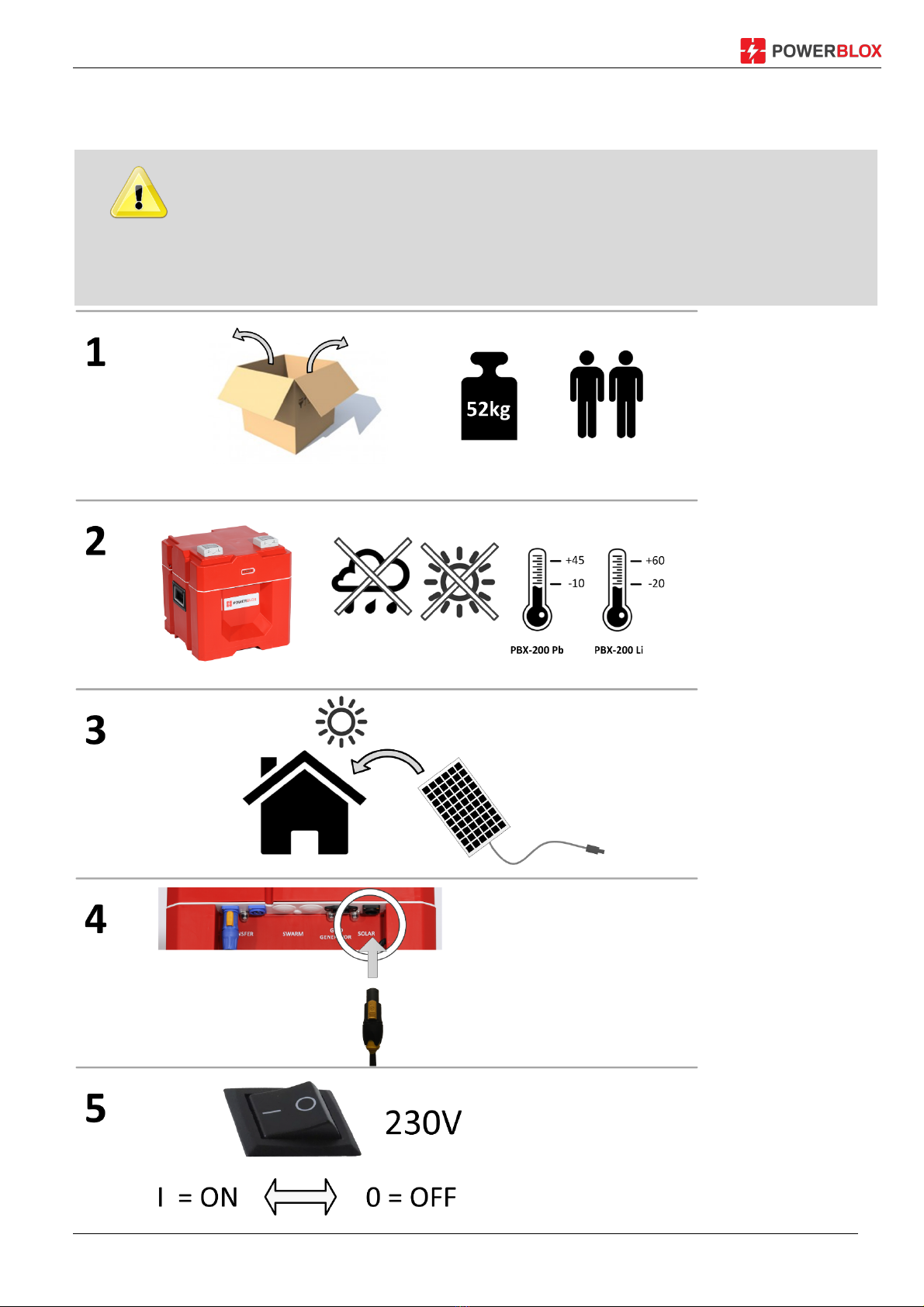
5!QUICK(START(GUIDE(......................................................................................................................................(7!
6!OVERVIEW(OF(THE(POWER(BLOX(..................................................................................................................(8!
6.1!LEGEND!OF!COMPONENTS!AND!CONNECTIONS!......................................................................................................!10!
7!INSTALLATION(.............................................................................................................................................(11!
7.1!SAFETY!INSTRUCTIONS!......................................................................................................................................!11!
7.2!CONNECTIONS!AND!MAIN!SWITCH!......................................................................................................................!13!
!"#"$!%&'()*+',-.)/01)""""""""""""""""""""""""""""""""""""""""""""""""""""""""""""""""""""""""""""""""""""""""""""""""""""""""""""""""""""""""""""""""""""""")$0!
!"#"#!2'34-,)-5((4-,'5()6'&)'(,473&,48)*5-94,*)/$1)"""""""""""""""""""""""""""""""""""""""""""""""""""""""""""""""""""""""""""""""""""""""""")$0!
!"#"0!:*4),.4):;<)-5((4-,53*)/=1)/>1)&(8)$#)?)2@)""""""""""""""""""""""""""""""""""""""""""""""""""""""""""""""""""""""""""""""""""""""""""")$=!
!"#"=!@5((4-,'(7),.4)*5A&3)B58CA4),5),.4)*5A&3)*5-94,)/D1)"""""""""""""""""""""""""""""""""""""""""""""""""""""""""""""""""""""""""""""")$=!
!"#">!@5CEA'(7)5F)G5+43H<A5I)""""""""""""""""""""""""""""""""""""""""""""""""""""""""""""""""""""""""""""""""""""""""""""""""""""""""""""""""""""""""""")$>!
!"#"J!%'('BCB)8'*,&(-4*)"""""""""""""""""""""""""""""""""""""""""""""""""""""""""""""""""""""""""""""""""""""""""""""""""""""""""""""""""""""""""""""""")$!!
!"#"!!K(,43-5((4-,'(7)*4643&A),5+43*),5)&)LE5+43)+&AAL)"""""""""""""""""""""""""""""""""""""""""""""""""""""""""""""""""""""""""""""""""")$!!
!"#"D!:*'(7),.4)-5((4-,'5(),43B'(&A*)/$JH$M1)"""""""""""""""""""""""""""""""""""""""""""""""""""""""""""""""""""""""""""""""""""""""""""""""""")$D!
7.3!CONNECTION!TYPES!.........................................................................................................................................!21!
7.4!SINGLE!SOLAR!SYSTEM!......................................................................................................................................!21!
7.5!COMBINATION!OF!SOLAR!AND!PUBLIC!ELECTRICITY!.................................................................................................!21!
7.6!USE!AS!BACKUP!SYSTEM!(UPS)!..........................................................................................................................!22!
7.7!COMBINED!SOLAR!/!MAINS!SYSTEM!WITH!CONNECTION!TO!THE!TERMINAL!BLOCK!.......................................................!22!
7.8!POWER-BLOX!INSTALLATION!.............................................................................................................................!23!
!"D"$!K(*,&AA&,'5()5F)&)*'(7A4)G5+43H<A5I)""""""""""""""""""""""""""""""""""""""""""""""""""""""""""""""""""""""""""""""""""""""""""""""""""""""""")#0!
!"D"#!K(*,&AA&,'5()5F)&88','5(&A)G5+43H<A5I),5)&),5+43)53)&)G5+43HN&AA)/B&I'BCB)M)C(',*1)"""""""""""""""""""""""""")#=!
!"D"0!K(*,&AA&,'5()5F)E5+43)*O*,4B*)734&,43),.&()M)G5+43H<A5I)"""""""""""""""""""""""""""""""""""""""""""""""""""""""""""""""""""""")#=!
8!INITIAL(START-UP(........................................................................................................................................(25!
9!LED(DISPLAY(................................................................................................................................................(26!
9.1!INDICATES!THE!BATTERY!STATUS!.........................................................................................................................!26!
9.2!DISPLAY!ON!SYNCHRONIZATION!..........................................................................................................................!26!
9.3!DISPLAY!OF!ERRORS!.........................................................................................................................................!26!
10!TROUBLESHOOTING
(..................................................................................................................................(27!
11!MAINTENANCE(............................................................................................................................................(28!
12!DISPOSAL(....................................................................................................................................................(29!
13!TECHNICAL(DATA(........................................................................................................................................(30!
14!DISCLAIMER(OF(LIABILITY(............................................................................................................................(32!
15!WARRANTY(AND(GUARANTEE(PROVISIONS(................................................................................................(33!
16!HOW(TO(CONTACT(WITH(.............................................................................................................................(37!
17!NOTES(.........................................................................................................................................................(38!

Installation and Operating Instructions PBX-200 PB / Li page 3
1 General Safety Instructions
§ This document is an integral part of the product. It is provided digitally and on request in
printed form.
§ Only qualified personnel are allowed to carry out the measures described in this manual.
§ Do not install or use the device until you have read and understood this document.
§ Always carry out the measures described in this document in the order indicated.
§ Save this document during the life of the device. Pass the document to the following owners
and users.
§ Improper operation can reduce the yield of the solar system or damage the system
components.
§ The device must not be connected with a damaged housing.
§ Disconnect the equipment immediately and disconnect from the solar module and the mains
/ generator if any of the following components are damaged:
— Device (no function, visible damage, smoke development, penetrated liquid etc.),
— connected lines,
— Solar module.
§ Do not switch on the system again before
— the device has been repaired by the dealer or manufacturer,
— damaged cables or solar modules have been repaired by a specialist.
§ Wash the battery immediately on skin or clothing with soapy water and rinse with plenty of
water. In case of injuries consult a doctor immediately.
§ Rinse immediately with plenty of water and seek medical advice.
§ Never cover the appliance.
§ Do not open the housing: Risk of death! Warranty claims forfeited!
§ Never affix the signs and markings affixed to the works, remove them or make them
unrecognizable.
§ If you are connecting an external device, which is not described in this document, please
follow the instructions of the manufacturer! Incorrectly connected devices can damage the
solar system.
§ This appliance is not intended for
— Children,
— People with physical, sensory or mental impairments,
— Persons who do not have sufficient experience and knowledge. Unless they have
been instructed and initially supervised by a person responsible for their safety.

Installation and Operating Instructions PBX-200 PB / Li page 4
2 Scope of delivery
§ 200 PBX or PBX 200-LI
§ Power cord
§ Quick Start Guide
§ Installation and operating instructions (online)
Optional accessories:
§ Solar cables with MC-4-port
§ WP 200 or 250 WP solar module
§ Print version installation and operating instructions

Installation and Operating Instructions PBX-200 PB / Li page 5
3 Intended use
The solar battery system, hereafter referred to as the power-Blox or System referred to, may be
used only in photovoltaic systems.
Furthermore,
§ Only solar modules can be connected to the solar module connector.
§ The connected loads must be suitable for the corresponding output voltage (230 V
alternating voltage, or 12 V / 5 V DC voltage).
§ The connected consumers must not exceed the maximum power of the system (for a
Power-Blox: 200 W, short-term 370 W).
§ The source connected to the GRID / GEN input must match the input voltage range of the
solar system and provide enough power.

Installation and Operating Instructions PBX-200 PB / Li page 6
4 Markings
4.1 Symbols for warnings and notes
Symbol
Description
General hazard warning
Danger with electricity
Important note
Read the instructions before using the product
4.2 Signal words
Symbol
Description
Danger
immediate risk of death or serious bodily harm
Warning
possible risk of death or serious personal injury
Caution
Possible risk of minor or moderate bodily injury
Attention
Possible property damage
Note
Note on the operation of the controller or on how to use the instructions

Installation and Operating Instructions PBX-200 PB / Li page 7
5 Quick Start Guide
DANGER!
Danger to life due to electrocution. Observe the safety instructions in section 9.1

Installation and Operating Instructions PBX-200 PB / Li page 8
6 Overview of the Power Blox
Figure 1: Power-Blox front page
Figure 2: Front connectors and power switch

Installation and Operating Instructions PBX-200 PB / Li page 9
Figure 3: Power-Blox back
Figure 4: Terminal connections behind cover installation

Installation and Operating Instructions PBX-200 PB / Li page 10
6.1 Legend of components and connections
1 AC power socket, 230 V
2 LED display
3 Main switch
4 Cigarette lighter socket 12 V DC, 3 A
5 2 x USB ports 5V, 2.1 A
6 Sockets for transfer cable
7 Cold devices power / generator (input) Jack
8 Solar connector for optional solar cable (input)
9 Transfer cable for connecting power-Blox
10 Vertical cable management channel
11 Horizontal cable ducts
12 Resettable circuit breaker (10 A) for transfer socket
13 Resettable circuit breaker (10 A) for mains / generator input
14 Installation flap for terminal connections
15 Anti-theft locking pins
16 Terminal block transfer connection
17 Not used
18 Terminal block for power / generator input
19 Solar connection terminal block
20 Strain relief bar

Installation and Operating Instructions PBX-200 PB / Li page 11
7 Installation
Only the installation of the power Blox is described below. When installing external
components (solar module, load, cable), observe the instructions of the respective
manufacturer.
Topics
1. Safety Instructions
2. Connections and Operation
3. Setting up the Power-Blox
4. Make electrical connections
7.1 Safety Instructions
DANGER!
Danger to life through electric shock! Observe the following safety instructions when
performing the steps described in the Installation section.
General
- Only qualified personnel are allowed to perform the measures described in the
"Installation" section.
- Power-Blox housing does not open.
The installation flap (14) must be closed and screwed during operation. Before working
with the Power-Blox, always carry out the following measures:
1. Switch off all consumers.
2. If present, open the DC load disconnector (solar module) and secure against
restarting.
3. Open external fuses in front of the generator / mains and transfer terminals and
secure against restarting.
Cabling
- The module cables carry voltage when the solar module is illuminated.
- If the terminals of the mains/generator input (18) are used, the pre-installed cables
must be removed from the terminal block and individually isolated.
- Isolate the open cable ends with an insulating tape or a luster clamp.
- Connect the cables from the solar module and the consumers to the Power-Blox in
the order described.
- Secure the connected cables with a strain relief (20).
- Connect only 1 line to each connection terminal.

Installation and Operating Instructions PBX-200 PB / Li page 12
- Cable: Refer to the Specifications section for details.
- Lay cables so that
— cannot accidentally disconnect connections,
— People cannot step on or stumble over it,
— Fire protection devices.
- Observe all applicable installation regulations and standards, national laws, as well
as the values of the regional power utility.
External circuit breakers
If the terminal blocks (16) - (18) are used for cabling, external circuit breakers as
specified in the section Technical data must be used.
WARNING: Model PBX 200 with lead batteries
Risk of injury from acid.
The Power-Blox contains two AGM lead batteries with 12 V and 50 Ah each.
- Do not expose the battery to open fire or sparks.
- Thoroughly ventilate the installation location of the Power-Blox. Flammable gases
can escape from the battery.
- Store Power-Blox dry.
- Do not expose the Power-Blox to temperatures above 60° C, for example, in closed
cars parked in the sun.
WARNING: Model PBX 200-LI with Li-Ion Batteries
Risk of fire.
The Power-Blox contains two Li-Ion batteries with 12 V and 50 Ah each.
- Do not expose the battery to open fire or sparks.
- Do not expose batteries to temperatures above 60 degrees or below -20 degrees
- Store battery dry
CAUTION!
Danger of damage to the Power-Blox due to overvoltage and overload:
- Observe the technical data, in particular the connection values. See type plate of the
solar module and chapter 13.
- When selecting the solar module, note that its open circuit voltage is higher than
indicated on the rating plate at temperatures below 25° C.
- Only connect one solar module per Power-Blox. Exception: Modules less than 100
Wp whose common open-circuit voltage (series circuit) is not greater than 45 V.
- The maximum open-circuit voltage of the solar module must not exceed 45 V. In
particular thin-film solar modules often have higher open-circuit voltages and are
therefore not suitable for Power-Blox.
- No solar modules with a common power of > 270 Wp.

Installation and Operating Instructions PBX-200 PB / Li page 13
7.2 Connections and main switch
The operation of the Power-Blox is very simple:
7.2.1 Main switch (3)
Power-Blox is controlled in normal use by a main control element: the main switch:
ON ßàOFF
The main switch is switched on by tilting to the left (position I). Tilt to the right (position O) turns
off the Power-Blox.
The Power-Blox starts into a boot and measuring cycle after switching on, so it does not deliver
power directly to the integrated sockets (1). Wait approximately one minute for the Power-Blox
to complete all tests and be ready for operation.
7.2.2 Direct connection via integrated sockets (1)
Figure 5: Use of the integrated sockets.
The two integrated AC power sockets deliver directly high-quality 230 V AC, similar to that at
your household socket. You can directly connect commercially available devices. Make sure you
do not exceed the maximum power of the Power-Blox.

Installation and Operating Instructions PBX-200 PB / Li page 14
7.2.3 Use the USB connectors (4) (5) and 12 V DC
Figure 6: The DC connectors on the front of the Power-Blox
If you want to use the Power-Blox DC power units, you have the possibility to connect a 12 V
device to the maximum of 3 A (car connection) and two USB devices up to 2.1 A at the front.
7.2.4 Connecting the solar module to the solar socket (8)
As an option, Power-Blox offers a solar cable with two standard MC4 connectors on the primary
side and a special solar plug on the secondary side. You can plug it directly into the Power-Blox.
Figure 7: Connect the solar module via solar cable
To connect the solar plug, turn it slightly to the left until it is completely inserted into the socket
and then turn it back until it snaps.
To release the solar plug, pull the yellow lock lever and then turn the plug to the left until it can
be pulled out.

Installation and Operating Instructions PBX-200 PB / Li page 15
For the connection of the solar module, it is not absolutely necessary to obtain a special
solar cable. The module can also be connected directly to the terminal block (19)
hidden behind the installation flap (14). Read more in the chapter 7.7.
7.2.5 Coupling of Power-Blox
By linking individual Power-Blox devices to a whole system, you can achieve several effects:
§ The performance of the entire system is increased
§ The memory of the combined system is increased
§ The daily energy yield is increased
The individual power elements can simply be added with such a coupling:
1 Power-Blox = 200 W Power, 1.2 kWh storage, 200 WP solar power
2 Power-Blox (coupled) = 400 W of Power, 2.4 kWh storage, 400 WP solar power
The individual Power-Blox is coupled by using the integrated transfer cable (9). This
approximately 1.7 m long cable makes it possible to connect vertically (stacked Power-Blox or
Power-Tower) or horizontally placed Power-Blox or towers (Power-Wall).

Installation and Operating Instructions PBX-200 PB / Li page 16
The figure below shows how
two Power-Blox can be
coupled together.
Before the two units are
coupled, switch off both units.
The transfer cable (9) of the
upper unit is now passed
through the cable guide
channel (10) and connected to
one of the two transfer
sockets (6) of the lower unit. It
does not matter which of the
two transfer sockets (6) is
used.
After switching on the two
Power-Blox both Power-Blox
synchronize and form a
"swarm net".
Up to three Power-Blox can
be connected to a tower and
several towers can be coupled
to each other.
Figure 8: Two coupled Power-Blox as a power tower
DANGER!
Do not form any towers that are higher than three units. Each Power-Blox weighs 52kg
and a tall tower could fall over and hurt you. Higher towers are unstable and can easily
tilt if they are not properly fixed or on a bad ground.
The resulting tower is provided at the sockets outlet (1) the power of all Power-Blox in the tower.
If you want to create larger mini-grids, go to chapter 7.8.3.

Installation and Operating Instructions PBX-200 PB / Li page 17
7.2.6 Minimum distances
Figure 9: Minimum distance between two Power-Blox (towers) and an adjacent wall
If you place several Power-Blox or Power-Towers next to each other, be sure to keep a
minimum distance between the units of at least 10cm. To an adjacent wall, the units should be
at least 20cm apart. This enables correct ventilation as well as safe handling.
If you have several tall towers next to each other, you can also make more sense to reach the
transfer cables and the integrated circuit breakers even after commissioning.
7.2.7 Interconnecting several towers to a "power wall"
Figure 10: Connect multiple power Blox towers
The interconnection of several towers takes place analogously to the coupling process
described in the previous chapter to a Power-Blox tower. In this case, the transfer cable (9) of
the lowest power-blox is connected to the transfer bush (6) of the neighboring tower.

Installation and Operating Instructions PBX-200 PB / Li page 18
Thus, the system delivers the performance of the entire system at one of the top sockets of a
tower. In our example, with 9 Power-Blox, this results in 9 x 200 W = 1.8 kW power, which can
be tapped at the socket. Please note that some types of sockets are designed for a lower
maximum power depending on the country specification.
7.2.8 Using the connection terminals (16-19)
DANGER!
Installations in which the connection terminals (16-19) are used may only be carried out
by qualified and trained specialists. In case of improper handling, life risks due to
electric shock as well as the risk of fire and destruction of individual components.
All connections of the Power-Blox are also available as terminals as an alternative to the plug
sockets. A connection to the terminals can be advantageous in the following situations:
§ Connection of a solar module with its own cable without special solar plug on the
secondary side (Power-Blox)
§ Connection of two solar modules in parallel connection (observe max. Power, see
technical data in chapter 13)
§ Connect two Power-Blox or towers over a larger distance, for example between two
buildings
§ Connection of a generator with a self-made cable
§ Connection to the public electricity network with a self-made cable
§ Connection to a fuse box, for example to supply a building installation
§ Connection to a fuse box for the coupling of several power-walls to a large plant
Before installation on Power-Blox terminals:
§ Turn Power-Blox off
§ Disconnect the power cable (7) from the Power-Blox
§ Disconnect the transfer cable from (9) and the (6) Power-Blox
§ Disconnect the solar cable (8) from the Power-Blox
§ Checking the LED display: It may not light
After these steps, the two locking screws (A) and (B) of the installation flap can be loosened with
a Phillips screwdriver:

Installation and Operating Instructions PBX-200 PB / Li page 19
Figure 11: Fuse screws of the installation flap
Now the terminal blocks for the connection of external cables are visible. In order to keep the
installation flap locked during the installation process, it can be pressed vertically vertically
downwards in the fully open position (stop point).
Prepare the cables according to the following drawing and push them as far as they will go into
the corresponding opening of the terminal:
Now close the terminals:
When closing, ensure that the clamp is fully closed and the bracket does not protrude:

Installation and Operating Instructions PBX-200 PB / Li page 20
After connection to the clamping block, the cable can be secured to the strain relief web (20) by
means of a cable tie.
Figure 12: Securing the cable with a cable tie on the strain relief bar
To feed the cable from the Power-Blox, the Power-Blox break-out tabs are provided in the
installation cover. In this case, break out a tab at a suitable location, for example with a side
cutter or a Japanese knife:
Figure 13: Tighten the tab to the cable entry
After completion of all installation work on the terminal blocks, close the installation flap and
secure it with the retaining screws (A) and (B).
Other manuals for PBX-200 PB
1
This manual suits for next models
1
Table of contents
Other Power-Blox Camera Accessories manuals
Popular Camera Accessories manuals by other brands

ZERO-X
ZERO-X ZX-G0 user manual

Manfrotto
Manfrotto MDOLLYVR instructions

Smart system
Smart system smartSlider Reflex Quick reference guide

EnerSys
EnerSys DataSafe 12HX1000F-FR Installation, operation and maintenance instructions

Energizer
Energizer 346 Product data sheet

PROAIM
PROAIM CINEMA Series Assembly manual