Power Designers PowerCharge iHF3 series User manual

MAN-230000-00 REV B
480 V Models
PCiHF-10kW-yyyA-zzV
Installation & Operation Manual
4005 Felland Road, Suite 116
Madison, WI 53718
USA
© Power Designers USA LLC
iHF3 Series

MAN-230000-00 REV B
TABLE OF CONTENTS
POWERCHARGE™ IHF3 SERIES ...........................................................................1
SAFETY PRECAUTIONS..........................................................................................2
POWERCHARGE™ IHF3 SPECIFICATIONS ..........................................................5
INSTALLATION PROCEDURE.................................................................................7
Charger Installation ......................................................................................7
Charger Electrical Installation....................................................................14
OPERATION PROCEDURE....................................................................................17
Charger Controls and User Interface ........................................................17
Getting Started ............................................................................................18
Charger Main Menu.....................................................................................22
TROUBLESHOOTING ............................................................................................32
RETURN MATERIAL PROCESS..........................................................................400
CHARGER PROGRAMMING................................................................................411
WARRANTY INFORMATION..................................................................................59
SOFTWARE LICENSE AGREEMENT..................................................................621
APPENDIX A –WALL MOUNT DIMENSIONS AND CLEARANCES ..................632
APPENDIX B –POST STAND DIMENSIONS AND CLEARANCES....................643
APPENDIX C –SHELF STAND DIMENSIONS AND CLEARANCES..................654
APPENDIX D –RECOVERY CYCLE FOR SULFATED BATTERY CURRENT AND
TIMER SETTINGS.................................................................................................665
APPENDIX E –NOTE ON TEMPERATURE COMPENSATION ..........................676
CONTACTING POWER DESIGNERS USA LLC..................................................687

MAN-230000-00 REV B 1
POWERCHARGE™iHF3 SERIES
The PowerCharge™iHF3 series of three-phase, high-frequency smart chargers
incorporates Metal-Oxide Semiconductor Field-Effect Transistor (MOSFET),
Insulated Gate Bipolar Transistor (IGBT) technology, and high-frequency
transformers, providing high electrical efficiencies (92% charging efficiency and 96%
power factor) in a compact package. PowerCharge™ iHF3 chargers are the lightest
and most-efficient chargers available on the market.
The PowerCharge™iHF3 chargers support standard, opportunity, and fast charge
cycles. iHF3 chargers also offer programmability. All charger settings and features
can be easily customized to match workloads and schedules. Finish and equalize
cycles may be automatically programmed to run on certain days of the week.
Additionally, PowerCharge™ iHF3 chargers may be tailored to meet the needs of
any battery chemistry, including flooded, gel, and Absorbed Glass Mat (AGM) lead-
acid batteries.
PowerCharge™ iHF3 480 VAC Battery Charger

MAN-230000-00 REV B 2
SAFETY PRECAUTIONS
BEFORE ATTEMPTING TO INSTALL AND OPERATE THE CHARGER, READ
THIS MANUAL CAREFULLY
This manual contains important instructions for the PowerCharge™ iHF3 series
product line that shall be followed during installation and operation of the charger.
Only qualified personnel should install, operate, or service this equipment.
SAVE THESE INSTRUCTIONS
High Voltages. Lethal voltages are present within the charger enclosure
whenever the AC line is energized and/or the battery/load is connected. The heat
sinks and other internal components present the risk of electric shock.
Stored Energy. To avoid the risk of electric shock, wait at least two minutes after
de-energizing the AC line and disconnecting the battery/load before removing the
cover.
High Current Levels. Do not touch uninsulated battery connectors or terminals.
All tools should be adequately insulated to avoid the possibility of shorting
connections. Inspect cables often for damage to the insulation. Replace cracked
or worn cables immediately.
Improper Connections. If the charger is incorrectly wired to input or output
devices or wiring is not in accordance with local safety codes and standards, the
iHF3 charger and/or its components are at risk of being destroyed.
Grounding. The charger must be connected to an AC power supply
incorporating an earth or ground. The grounding conductor must be of a size
equal to or larger than the line (phase) conductors.
Explosive Gases.Working in the vicinity of a lead-acid battery is dangerous.
Batteries generate explosive gases during charge and discharge. To reduce the
risk of ignition, follow these safety instructions as well as those published by the
battery manufacturer. To minimize the potential for arcing and to reduce the risk
of damage to the connector contacts, it is preferable to connect and disconnect a
battery when the charger output is OFF.
WARNING

MAN-230000-00 REV B 3
Chemical Hazard. Working with lead-acid batteries may result in exposure to
highly corrosive acid. To protect eyes and skin, use the required Personal
Protective Equipment (PPE)as mandated by your employer and local
regulations. At a minimum, wear safety goggles and skin protection while
connecting the battery charger or working in the vicinity of lead-acid batteries.
Follow the battery manufacturer's published instructions when installing,
charging, and servicing batteries.
Use only with rechargeable batteries. Do not attempt to charge other battery
types; doing so may cause equipment damage and result in serious personal
injury.
Do not expose the charger to rain or snow. The charger is NOT designed for
outdoor use.
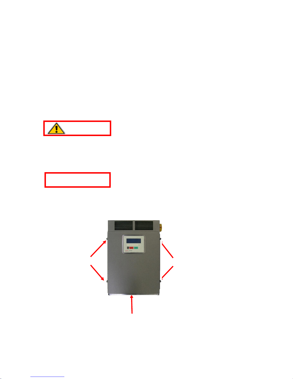
Adequate Cooling Required. To prevent damage from overheating, proper
airflow must be ensured. Do not restrict fan inlets or exhaust outlets. Do not
mount the charger in a confined space or where the exhaust air will recirculate.
No User Serviceable Parts.If service is required, contact Power Designers USA
LLC or its service representative.
These instructions assume a certain level of competence by the installer
and/or user. The following practices and codes contain relevant information, and
should be consulted for safe installation, testing, handling, and maintenance of
rechargeable lead-acid batteries. All applicable state and local codes must be
followed.
National Electric Safety Code (NESC), ANSI/IEEE C2-2007 (or latest
revision). Copies may be obtained by contacting: The Institute of Electrical
and Electronics Engineers, Inc. (IEEE), Publications Office, 10662 Los
Vaqueros Circle, P.O. Box 3014, Los Alamitos, CA 90720
www.ieee.org
National Electrical Code (NEC) NFPA-70 (or latest version) available from:
National Fire Protection Association, 1 Batterymarch Park, Quincy, MA 02269
www.nfpa.org
CAUTION
WARNING

MAN-230000-00 REV B 4
Federal Codes
29CFR1926.441 Batteries and Battery Chargers
29CFR1910.305 (j) Wiring Methods, Components and Equipment for General
Use
OSHA Directive STD 01-08-002, including 29CFR1910.151(c) Medical
Services and First Aid; 29CFR1926.50 and 29CFR1926.51, Medical Service
and First Aid, and Sanitation, respectively; applicable to electric storage
battery charging and maintenance areas.
EMC Compliance
This device complies with Part 15 section 103 of FCC Rules as a digital
device used exclusively as a power system in public utilities or industrial
plants.
Operation is subject to the following two conditions:
1. This device may not cause harmful interference.
2. This device must accept any interference received, including interference
that may cause undesired operation.

MAN-230000-00 REV B 5
POWERCHARGE™ iHF3 SPECIFICATIONS
480 V Model Numbers
PCiHF-10kW-250A-36V
PCiHF-10kW-250A-48V
PCiHF-10kW-120A-80V
Figure 1: PowerCharge™iHF3 10 kW Battery Charger features
LCD/keypa
d
Knockout
for input
wiring
Strain
reliefs
for
output
cables
Lift
handles
Lift
handle
s
Air
filter
AC
disconnect
switch
Optional
Ethernet

MAN-230000-00 REV B 6
Specifications for the PowerCharge™iHF3 480 VAC 10 kW models.
Specifications
PCiHF10kW-
250A-36V
PCiHF10kW-
250A-48V
PCiHF-10kW -
120A- 80V
Nominal VA Ratings
36 V / 250 A
48 V / 250 A
80 V / 120 A
Input Specifications
Voltage
400–480 VAC, ± 10%, 3-phase with earth ground
Current (Nominal)
13.8 Arms @480 V, 16.7 Arms @400 V
AC Circuit Size
20 A / 25 A
Power Factor
0.96 nominal
Output Specifications
Voltage
36 V nom. /
62.5 V max.
48 V nom. /
62.5 V max.
80 V nom. /
110 V max
Current
250 A max.
250 A max.
120 A max
Power
10 kW max.
10 kW max.
10 kW max.
Pk-Pk Voltage Ripple
< 1%
Efficiency (Typical)
92% at full load
Protection
Input
Under voltage
Over voltage transients
Output
Over current
Over voltage
Over temperature
Battery reverse polarity protection
Operating Conditions
Ambient Temperature
0–40oC
Humidity
10–90% RH noncondensing
Interface
Communication
Isolated RS-232 (Ethernet optional)
User Interface
LCD/keypad, RS-232, IR
Cooling
Forced air (fans)
Mechanical
Dim. WxDxH
20.1" x 9.3" x 26.3"
Weight
~ 98 lb
Output Cabling
2/0 cables
Output Connectors
SBX w/ aux. contacts or Euro connector
Auxiliary Contacts
Interface with 5kbattery thermistor (optional)
Certifications
UL and cUL Listed

MAN-230000-00 REV B 7
INSTALLATION PROCEDURE
Charger Installation
The following procedure describes proper installation of PowerCharge™ iHF3
series chargers.
Charger Unpacking and Inspection
Upon receipt of the PowerCharge™, ensure that there is no physical damage to the
chassis, the Liquid Crystal Display (LCD)/keypad, the AC disconnect switch, or the
DC cables. If any damage is apparent, contact the shipping carrier.
Do not install or operate the charger if it has any visible damage.
Ensure that the charging area is well ventilated, dry, and clean.
1. Lifting the Charger
Never lift the charger from the middle of the lower cover, as this will damage
the air filter. Use the lift handles mounted on either side of the charger chassis
(Figure 2).
Figure 2: Charger lifting points
X
NO LIFT
Lift handles
Lift handles
WARNING
CAUTION

MAN-230000-00 REV B 8
2. Charger Physical Installation
Ensure that the charging area is well ventilated, dry, and clean.
There must be at least one foot of spacing between the sides of the charger
and any adjacent walls or barriers, and two feet of spacing between the
bottom of the charger and the floor or any other obstruction. A minimum of
six inches of spacing between the bottom of the charger and the floor is
acceptable if using one of the floor stand mounting options. If this option is used,
the air filter must be inspected and cleaned more frequently.
Do not restrict airflow to the air filter at the bottom of the charger or to the
vents at the top of the charger.
There are three mounting options available for the iHF3 charger: standard wall
mount, optional floor-mounted post stand, or shelf stand.
a. Wall Mount Option
i. Dimensions and clearances for the wall mount option are shown in
Appendix A, page 63 of this manual.
ii. Using the mounting-hole pattern (Figure 3), mark the locations for the
mounting hardware on the wall. Use 1/4-20 fasteners with lock and flat
washers to secure the charger to the wall.
Figure 3: Wall-mount hole pattern
18.6
6
19.25
CAUTION

MAN-230000-00 REV B 9
b. Post Stand Option
i. The post stand (Figure 4) provides a convenient floor-mount option. The
charger mounts to the stand using 1/4-20 hardware provided with the post
stand. It is also available with a pogo stick cable management system,
providing easy connection to the battery and keeping cables off the floor
when not connected. Dimensions and clearances are detailed in Appendix
B, page 64 of this manual.
Figure 4: Post stand

MAN-230000-00 REV B 10
ii. The post stand should be bolted to the floor using the hole pattern shown
(Figure 5). The post-stand base plate has four 0.55-inch diameter holes
suitable for ½-inch mounting hardware. Note that the holes in the upper
portion of the base plate section must be on the left and right sides
of the installation (Figure 7).
Figure 5: Post-stand mounting-bolt pattern
iii. The post-stand brackets (Figure 6) are fastened to the inside of the base
plate, using the supplied 1/4-20 bolts and lock washers. Finger-tighten
only at this time. Again, note the brackets are on the left and right
sides of the installation.
Figure 6: Post-stand bracket
iv. The upper section of the post stand can now be placed over the top of the
base plate and brackets. Note the mounting studs for the iHF3 charger are
on the front surface of the upper section. Fasten the upper section to the
post-stand brackets with the supplied 1/4-20 bolts and lock washers. All of
the bracket bolts can now be fully tightened.

MAN-230000-00 REV B 11
v. The charger can now be lifted onto the mounting studs of the post stand
and fastened with the supplied 1/4-20 nuts and flat washers.
Figure 7: Assembled post-stand base
c. Shelf Stand Option
i. The shelf stand (Figure 8) provides another convenient mounting option.
Complete dimensions and clearances are given in Appendix C, page 65 of
this manual.
ii. The shelf stand is typically bolted to open shelving using the hole pattern
(Figure 9). The shelf-stand base plate has six 0.31-inch diameter
clearance holes for 1/4-20 mounting hardware.

MAN-230000-00 REV B 12
Figure 8: Shelf stand
Figure 9: Shelf-stand mounting-bolt pattern
NOTE:
Dimension A
critical for
open shelf
mounting

MAN-230000-00 REV B 13
3. Air Filter
The charger is equipped with an air filter located in the bottom of the chassis.
The air filter needs to be checked on a monthly basis and cleaned if needed. If
the charger is mounted less than two feet from the floor or other obstruction, the
air filter will need to be checked and cleaned more often.
To remove the filter, grasp the open (front) side of the filter, depress the spring
retainer on the left side of the charger, and slide the filter out.
ATTENTION: Before installing, clean the filter using soap and water and dry
thoroughly, or blow out debris in the opposite direction of airflow with
compressed air.
To reinstall, slide the filter into the guides and push in until fully inserted (Figure
10).
Figure 10: Installing/reinstalling the air filter
ATTENTION: When reinstalling the filter or installing a new filter, make sure
that the filter side with the wire frame is facing upward. Also, the front of
the filter has an arrow showing airflow direction; the arrow should be
facing into the charger.
Air filter
Filter
spring
retainer
Air filter
screen

MAN-230000-00 REV B 14
Charger Electrical Installation
DANGEROUS VOLTAGES AND CURRENTS ARE PRESENT IN THE AC MAINS
WHEN ENERGIZED. ONLY TRAINED PERSONNEL SHOULD PERFORM THESE
PROCEDURES, USING PROPER EQUIPMENT AND PROCEDURES.
VERIFY THAT INPUT AND OUTPUT WIRING ADHERES TO ALL LOCAL SAFETY
CODES AND STANDARDS.
1. PowerCharge™ iHF3chargers require a 480 VAC 3, four-wire Wye or
Delta electrical supply with a separate ground (Figure 11). Nominal 480
VAC current draw is 13.8 A; circuit disconnect at 125% should be 20 A.
Figure 11: AC input wiring diagrams
2. Verify that the source circuit is locked and tagged out before connecting
power to the charger.
3. Verify that the AC disconnect switch on the charger is in the OFF position (Figure
12).
GND
Typical Delta circuit
Wye circuit
A
B
C
240V
415V
480V
480V
240V
C
B
A
277V
277V
480V
277V
480V
480V
GND
480V
WARNING

MAN-230000-00 REV B 15
Figure 12: AC disconnect switch
4. Open the top of the charger by loosening the four mounting screws and lifting the
cover off.
5. Push out the knockout (Figure 13) and pass the 480 VAC input power wires
through, using the appropriate conduit or strain relief fittings per local and
national codes.
6. Crimp a #10 ring tongue terminal (12-10 American Wire Gauge (AWG)) to the
ground (GND) wire and connect it to the GND terminal (Figure 13). Torque the
nut to 20 in-lb.
7. Strip the conductors back 0.5 inch (12 mm) and connect them to the disconnect
switch where labeled 480 VAC 3in Figure 13. Torque the terminal screws to
20 in-lb. NOTE: The charger is not phase-rotation sensitive.
AC
disconnect
switch

MAN-230000-00 REV B 16
Figure 13: Charger electrical connection points
8. Verify the line and ground connections of the outlet or junction box/disconnect.
9. With the charger switch OFF, energize the source circuit and verify proper AC
voltage at the line side of the charger switch. All line-to-line voltages should be
400–480 VAC ± 10% and matched within 10 VAC. De-energize the source
circuit.
10. Verify that the source circuit is locked and tagged out. Replace the top cover on
the charger, securing it with the four mounting screws.
THE CHARGER IS NOW READY FOR OPERATION
AC knockout
480 VAC
3
GND

MAN-230000-00 REV B 17
OPERATION PROCEDURE
Charger Controls and User Interface
Users operate the PowerCharge™ iHF3series of chargers through each charger’s
front panel LCD/keypad (Figure 14).
This is the main user interface for viewing and displaying operation and fault
messages. It also allows limited charger programming options. (For programming
information, see CHARGER PROGRAMMING, page 42 of this manual.)
Figure 14: User interface LCD/keypad
RS-232
port
IR window
LCD
Function
keys

MAN-230000-00 REV B 18
Getting Started
The LCD display on the PowerCharge™ iHF3series presents various screens and
SCREEN MESSAGES.
1. Powering the Charger
a. Energize the AC mains.
b. Turn the AC disconnect switch to the ON position.
c. Verify that the LCD display is lit and displays the CONNECT BATTERY
screen. The LCD displays the battery voltage setting and the maximum
current setting on the first line (e.g., 48 V and 200 A).
0
4
8
V
2
0
0
A
0
4
/
1
5
/
2
0
1
1
1
2
:
0
0
:
0
0
C
O
N
N
E
C
T
B
A
T
T
E
R
Y
D
I
S
P
L
A
Y
d. If the LCD is not lit, or if the message is not displayed, cycle the switch to the
OFF position and then return it to the ON position.
DANGEROUS VOLTAGES AND CURRENTS ARE PRESENT IN THE AC
MAINS WHEN ENERGIZED. ONLY TRAINED PERSONNEL SHOULD
PERFORM THESE CHECKS, USING PROPER EQUIPMENT AND
PROCEDURES.
e. If the charger still does not power up, carefully verify the source circuit and
wiring to the charger and correct any problems. Check that the fuses in the
AC mains junction box on the wall are intact, and that the supply voltage for
all three phases (AC mains line-to-line) is 400 V–480 V ± 10%, and matches
to 10 VAC or better.
f. Restart the charger; if the problem persists, contact the dealer or Power
Designers USA LLC.
WARNING
Table of contents