manuals.online logo
Brands
  1. Home
  2. •
  3. Brands
  4. •
  5. Chargetek
  6. •
  7. Batteries Charger
  8. •
  9. Chargetek RTIC-1120-FC User manual

Chargetek RTIC-1120-FC User manual

Charger operation
The RTIC-1120-FC is fully automatic once installed properly.
The LED indicator lights inform the user of the progress of the

Electrical characteristics
LED indicators
Charging mode: Indicates the state of charge of the battery.
The green Float light indicates the battery is fully charged.
Charging current LEDs indicate amount of current.
AC Power On LED indicates AC power is applied to the
charger.
Charging status LED indicates the output is connected
properly to the battery and is being charged.
Please read the entire installation manual before installing
the battery charger. If there are any questions or concerns,
please email us or call our toll-free number given below.
The RTIC-1120-FC is a rugged, waterproof and sophisti-
cated three state lead-acid battery charger. With a wide
-
tion, this product is especially suited for high end industrial
applications and severe environments.
The RTIC-1120-FC is factory programmable to accom-
modate several charging algorithms, an LED display to
indicate status, and optional four relay contacts to indicate
various scenarios. Temperature compensation is imple-
mented digitally allowing accurate and noise free sensing
up to a distance of 300 feet eliminating problems associ-
ated with conventional analog solutions.
The charging algorithm, LEDs, and relay control signals
are generated by an embedded microcontroller that con-
tains software developed by and proprietary to Chargetek.
The RTIC-1120-FC precisely controls charging voltage and
current to ensure a complete recharge every time. The

maintaining a full charge.
RTIC-1120-FC
Installation Manual
Protection modes
Over temperature: The unit inhibits until it cools off and then
restarts automatically. This is indicated by the AC Power and

possible for the non-auto reset thermal protection to activate.
This is indicated by the AC Power on and 14-20 Amp Charging

disconnected and reconnected once the charger has cooled off.
Over voltage: Activates in the event of a regulation malfunction
and inhibits the charger. An over voltage condition is indicated

persists, the factory should be consulted.
Optional relay contacts
Up to four relay contacts are provided depending upon the op-


proper operation.
Optional temperature compensation
The temperature compensation pod can be tie-wrapped to the
charger cable in the immediate vicinity of the battery or wall
mounted. Standard compensation is 15mV-18mV per degree
Celsius per cell or factory programmable upon request.
Optional signal connector
Chargetek
409 Calle San Pablo, Unit 104, Camarillo, CA 93012 ~ Phone: (866) 482-7930 ~ Fax: (805) 482-7936

PIN NUMBER SIGNAL DESCRIPTION
2,8 AC Fail AC < 85VAC
3,9 DC High DC > 15.5VDC
4,10 DC Low DC < 6VDC
1,7 Charger Fail Unit failed
11 TC Data Temp sense data line
12 TC Rtn Temp sense bias rtn
6 TC Bias Temp sense bias power
PARAMETER DESCRIPTION / CONDITIONS MIN NOM MAX UNITS
VFSTERM Fast charge voltage, 25C 14.4 14.5 14.6 VDC
VFLOAT Float voltage, IOUT < 1.0 A, 25C 13.2 13.4 13.6 VDC
IFS Fast charge, VBATTERY = 12V 20 21 22 Amps
IFLTERM Float charge termination current 3.2 3.4 3.6 Amps
VAC RMS AC voltage range 90 120 132 VAC
ISBY Standby current, AC off 0.5 ma
Dimensions in inches
Outline and mounting
LIMITED WARRANTY
For two years from date of purchase, Chargetek Inc. will at its discretion repair or replace for the original consumer, free of
charge, any part or parts found to be defective by Chargetek in workmanship or material. All shipping charges under this
warranty must be paid by the consumer. Proof of purchase is required.
                
purpose are limited to two years from the date of purchase. This is the exclusive remedy and consequential damages are
excluded where permitted by law.
The RTIC-1120-FC is short circuit protected. Batteries are
a high current source and additional protection is needed
in the event of physical damage to the DC cables or the
charger, or electrical damage that may be externally induced.
Do not remove the in-line fuse. A fuse (ATO mini/32V/30A)
connected between the positive battery charger lead and the
battery positive terminal is required for maximum safety. If
the fuse ever blows, consult the factory before replacing it.
For a single 12 volt battery, connect the charger DC cable to
the battery as follows: the red lead is connected to positive
terminal of the battery and the black lead is connected to
the negative terminal of the battery. When charging two 6
volt batteries connected in a series, connect the red lead of
the charger to the positive terminal of battery #1. Connect
the negative terminal of battery #1 to the positive terminal
of battery #2. Connect the black lead of the charger to the
negative terminal of battery #2. All connections should be
clean and tight. See installation diagrams below.
When connecting two batteries in series, it is imperative
that the amount of charge and discharge be equal for
both batteries. If there is an imbalance during charge or
discharge, excessive battery voltage will occur. This results
in an overvoltaged battery and causes dangerous battery out
gassing and destruction. For accurate charge balancing, use
a dual bank charger, such as CT500 or TPRO series.
Safety instructions
CAUTION: The following are important safety instructions.
Save these instructions.

cell” rechargeable batteries. Other types of batteries may
burst causing personal injury or damage.
           
battery.
Someone should be within the range of your voice and close
enough to come to your aid when you are working near a
battery.
Wear eye protection and clothing protection. Avoid touching
your eyes while working near a battery.
Have plenty of fresh water and soap nearby in case battery
acid contacts your skin, clothing or eyes.
If battery acid contacts skin or clothing, wash immediately
with soap and water. If acid enters your eyes, immediately

and get immediate medical attention.
Never operate a charger with a damaged cord or plug.
Degradation of AC and DC cords, accidentally nicking or
cutting the cords could result in sparking and cause injury.
Never operate a charger that has been damaged in any way
or try to disassemble it. Return it to the factory when service
or replacement is required. Incorrect reassembly may result

      
cautionary markings on chargers, batteries and equipment
used. Only adults should install and operate the charger.
The charger and batteries should be kept out of the reach of
children.
When using an extension cord, the RTIC-1120-FC requires a
quality grounded extension cord of at least 16 awg wire size
for cords up to 50 feet and a minimum of 14 awg for cords
up to 150 feet.
Never unplug a cord by pulling on the cord itself. Always
grasp the plug when disconnecting the charger.
The RTIC-1120-FC is waterproof and designed for harsh
environments. It is not designed to be submerged. Please
consult the factory if there are any questions.
Never charge a frozen battery. If the battery has an odor or
is visibly damaged, disconnect the charger and consult the
factory.
Study the battery manufacturer’s precautions such as
removing or not removing cell caps while charging.
Keep batteries full. Add distilled water in each cell until it


Good battery maintenance procedures dictate that the battery

ambient temperatures.
Keep the battery terminals clean. Always unplug the charger
before cleaning. Keep corrosion from coming into contact
with your eyes.
Remove personal metal items such as rings, bracelets,
necklaces, and watches when working with a lead-acid
battery. A lead-acid battery can produce a short circuit high
enough to weld objects to metal, causing a severe burn.
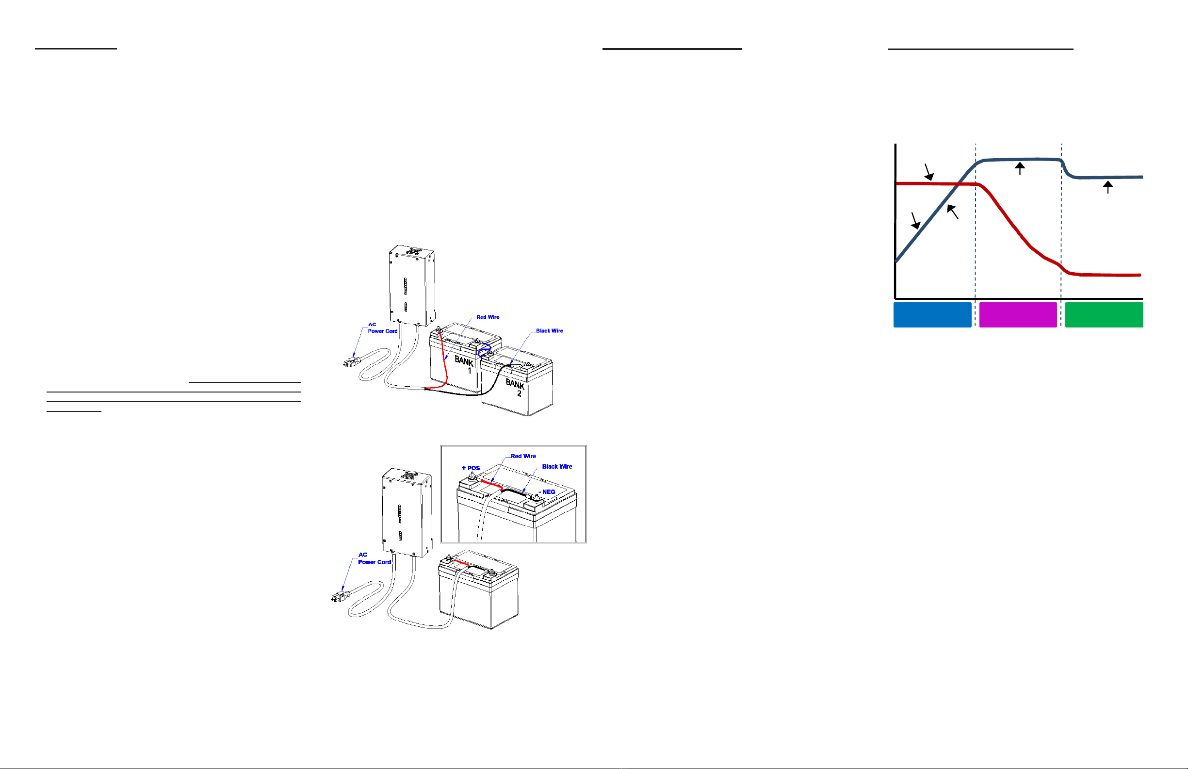
Three stage charging curve
Three stage charge cycle
The RTIC-1120-FC employs a three stage charge routine. This
is the charging procedure most lead-acid battery manufactur-
        
battery life.
Stage 1: Constant current or bulk charge mode
Assuming that the battery is starting in a discharged state, the
charger is operating in constant current mode. The charger
current is maintained at a constant value and the battery voltage
is allowed to rise as it is being recharged. Approximately 80%
of battery capacity is returned in the constant current region.
Stage 2: Absorption mode
When the battery voltage reaches approximately 2.4 volts per
cell, or 14.4 volts for a 12V battery, the charger voltage is held
constant at this level and the battery current is allowed to reduce.
This voltage is maintained until the charging current reduces
substantially indicating a full charge. At this point, the battery
is fully charged.
Stage 3: Float mode

mode, the voltage on the battery is maintained at approximately
13.5 volts for a 12V battery. This voltage will maintain the full
charge condition of the battery without boiling out electrolyte
or overcharging the battery. When the charger is in this mode,
all lights on the RTIC-1120-FC should be green.
Installation
Location
Do not mount directly over or under a battery or onto a
carpeted, upholstered or varnished surface.
Install in an area where all charger electrical cords will avoid
hot surfaces such as exhaust pipes and moving parts such
as fan wheels.
Operating temperature is -30°C to 55°C (-22°F to 131°F).
Storage temperature is -40°C to 80°C (-40°F to 176°F).
Provide as much surrounding cooling clearance as possible

At a minimum, maintain a 3 inch clearance around the pe-
rimeter and top side of the charger.
Never mount in the vicinity of explosives, pressurized cans

Mounting
Wear safety goggles, gloves and a long sleeve shirt when
drilling mounting holes near a battery.
Please see outline and mounting diagram for proper mounting.
Electrical
AC wire connections
The RTIC-1120-FC is equipped with a factory installed 6 foot
AC cord with a ground connection. The ground connection
is the round pin on the AC plug. It is extremely important
that only grounded electrical outlets or extension cords
with a ground connection should be used when operating
this charger.
Never connect the AC plug into an electrical outlet if you
are wet or barefoot.
Ensure that the AC cord cannot reach moving parts, lids,
hoods, etc. Secure with a cable tie to solid anchor point if
necessary.
The charger will operate properly with either 115 volts 50
Hz or 115 volts 60 Hz AC input. Never use 220 volt service
with this unit.
DC wire connections
DC wire connections must be made before plugging in the
AC cord.
The charger should only be used with lead-acid type batteries

any question, please contact the factory.
Do not remove DC connections while the AC cord is plugged
in.
When installing in the bilge of boats or any battery
compartment, ensure that hatches are open and bilge blowers
are operating for ten minutes to remove any fumes and
hydrogen gas. Be certain the area is ventilated for personal
health and safety.
Keep wire routing from the charger to the battery neat and
secure by anchoring with cable tie to a solid surface every
few inches, not to exceed 18 inch intervals.
       
parts and hot surfaces such as exhaust components.
Battery
voltage
Stage 1: Bulk
(constant current)
Stage 2: Absorption
(constant voltage)
Voltage constant,
current decreasing
Battery
current
Absorption
Voltage constant,
full charge maintained
Stage 3: Float
(constant voltage)
Float
Bulk
Two 6V battery connection
One 12V battery connection

Other Chargetek Batteries Charger manuals

Chargetek RTIC-2120-FC User manual

Chargetek

Chargetek RTIC-2120-FC User manual

Chargetek RTIC-1307-WP User manual

Chargetek

Chargetek RTIC-1307-WP User manual

Chargetek CT500-3 User manual

Chargetek

Chargetek CT500-3 User manual

Chargetek RTIC-2307-FC User manual

Chargetek

Chargetek RTIC-2307-FC User manual

Chargetek RTIC-2307 User manual

Chargetek

Chargetek RTIC-2307 User manual

Chargetek RTIC-2210-FC User manual

Chargetek

Chargetek RTIC-2210-FC User manual

Chargetek CT500-6 User manual

Chargetek

Chargetek CT500-6 User manual

Chargetek RTIC-1405-FC User manual

Chargetek

Chargetek RTIC-1405-FC User manual

Chargetek RTIC-1307-FC User manual

Chargetek

Chargetek RTIC-1307-FC User manual

Chargetek TPRO-220 User manual

Chargetek

Chargetek TPRO-220 User manual

Chargetek CK150-2 User manual

Chargetek

Chargetek CK150-2 User manual

Chargetek RTIC 2405-WP User manual

Chargetek

Chargetek RTIC 2405-WP User manual

Chargetek RTIC-1120-W User manual

Chargetek

Chargetek RTIC-1120-W User manual

Chargetek RTIC-1405-WP User manual

Chargetek

Chargetek RTIC-1405-WP User manual

Chargetek CT500 - 1 User manual

Chargetek

Chargetek CT500 - 1 User manual

Chargetek RTIC 1120-WP User manual

Chargetek

Chargetek RTIC 1120-WP User manual

Chargetek CT500-5 User manual

Chargetek

Chargetek CT500-5 User manual

Chargetek RTIC-2210-WP User manual

Chargetek

Chargetek RTIC-2210-WP User manual

Chargetek RTIC-1210-FC User manual

Chargetek

Chargetek RTIC-1210-FC User manual

Chargetek RTIC-1210 User manual

Chargetek

Chargetek RTIC-1210 User manual

Chargetek TPRO-320 User manual

Chargetek

Chargetek TPRO-320 User manual

Chargetek RTIC-1120-WP User manual

Chargetek

Chargetek RTIC-1120-WP User manual

Chargetek CT500-2 User manual

Chargetek

Chargetek CT500-2 User manual

Chargetek CK150-4 User manual

Chargetek

Chargetek CK150-4 User manual

Popular Batteries Charger manuals by other brands

Victron energy Blue Power Automotive IP65 Charger 12V/4A -... manual

Victron energy

Victron energy Blue Power Automotive IP65 Charger 12V/4A -... manual

Emos N9168S manual

Emos

Emos N9168S manual

National Luna BMS-60010 user manual

National Luna

National Luna BMS-60010 user manual

Lenmar Lenmar PRO9V2 instruction manual

Lenmar

Lenmar Lenmar PRO9V2 instruction manual

DNS AC47CM1 user manual

DNS

DNS AC47CM1 user manual

ENGIE EPS easyWallbox user manual

ENGIE EPS

ENGIE EPS easyWallbox user manual

Insignia NS-CAHCC02 Quick setup guide

Insignia

Insignia NS-CAHCC02 Quick setup guide

satmap Standard Power Bundle user guide

satmap

satmap Standard Power Bundle user guide

Echo LC-56V2A Operator's manual

Echo

Echo LC-56V2A Operator's manual

Würth 0510 955 750 Operation manual

Würth

Würth 0510 955 750 Operation manual

RCA WP4UAR user guide

RCA

RCA WP4UAR user guide

GMC Ultium user manual

GMC

GMC Ultium user manual

VOLTCRAFT QCP-2400 operating instructions

VOLTCRAFT

VOLTCRAFT QCP-2400 operating instructions

Vertiv CE-P 2.5A 30/48 Installation and user guide

Vertiv

Vertiv CE-P 2.5A 30/48 Installation and user guide

REV Ritter EU101WL-GR manual

REV Ritter

REV Ritter EU101WL-GR manual

NOCO Genius GENIUS2 User guide & warranty

NOCO Genius

NOCO Genius GENIUS2 User guide & warranty

Mous A154-176-MAGWCH user manual

Mous

Mous A154-176-MAGWCH user manual

EcoFlow RIVER Pro user manual

EcoFlow

EcoFlow RIVER Pro user manual

manuals.online logo
manuals.online logoBrands
  • About & Mission
  • Contact us
  • Privacy Policy
  • Terms and Conditions

Copyright 2025 Manuals.Online. All Rights Reserved.