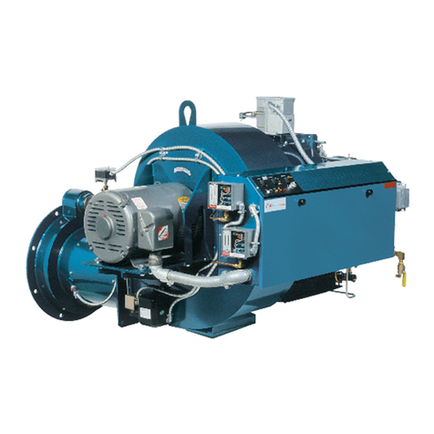
Power Flame EVO User manual

EVO MANUAL

2
POWER FLAME MODEL EVO®BURNER
For use by Qualified Service Personnel Only
WARNING
The improper installation, adjustment, alteration, service, or maintenance
of this equipment can result in fire, explosion, serious injury, or death.
Refer to this manual. For assistance or additional information consult a
qualified installer, service agency or the gas supplier.
Do not store or use gasoline or any other flammable liquids in the vicinity
of this or any other appliance.
ATTENTION!
All Personnel involved with the startup, maintenance, or adjustment of this burner must read
and understand the entire contents of this manual prior to any startup or adjustment made to
the burner and related components. Installation and service must be performed by a qualified
installer, service agency or the gas supplier.
WHAT TO DO IF YOU SMELL GAS
1. Do not try to light any appliance
2. Do not touch any electrical switch
3. Do not use any phone in your building
4. Immediately call your gas supplier from a neighbor’s phone
5. Follow the gas supplier’s instructions
6. If you cannot reach your gas supplier, call the fire department
EVO®Installation and Operation Manual

EVO®Installation and Operation Manual
1. GENERAL PRODUCT INFORMATION 1
1.1 Principle of Operation 1
1.2 Unpacking and Handling 1
1.3 Warranty and Spare Parts Information 1
1.4 General Components Information 2
2. INSTALLATION 6
2.1 Gas Supply Piping 6
2.2 Combustion Air Requirements 7
2.3 Burner Mounting: General 7
2.4 Combustion Chamber: General 9
2.5 Extreme Temperature Operation: General 9
3. START UP PROCEDURES 10
3.1 Burner Start Up and Service Test Equipment Required 10
3.2 General Start-Up All Fuels 10
3.3 Burner Start-Up Sequence Instructions: Gas 11
4. TROUBLESHOOTING 15
4.1 Gas Pilot Ignition Adjustment 15
4.2 Gas Pilot Flood Test 15
4.3 Trouble Shooting Suggestions: general 16
4.4 Trouble Shooting Suggestions: Gas 16
5. MAINTENANCE 18
5.1 General Information 18
5.2 Periodic Check List 19
6. BURNER START UP INFORMATION & TEST DATA 20

4
1. GENERAL PRODUCT INFORMATION
1.1 Principle of Operation
1.1.1 The Power Flame Model EVO®Burner, U.S. Patent #11,585,528, is a forced draft, partial premix/nozzle
mix, staged gas burner designed for Sub 30 PPM NOx emissions without the use of Flue Gas Recirculation,
while maintaining 3% O2, when firing with typical Natural Gas fuel. The Model EVO®burner is listed and
labeled by Underwriters Laboratories, Inc. up to EVO800. The combustion air is furnished by an integrally
mounted combustion air fan. The Power Flame packaged combustion system can be operated under
positive or negative furnace pressures with clean, efficient combustion in a wide range of combustion
chamber conditions.
1.1.2 The Power Flame Model EVO®burner is a totally packaged and factory tested combustion system offering
single unit responsibility. The package incorporates accurate control of the fuel-air ratio throughout the firing
range with the resultant controlled flame patterns and clean combustion for maximum efficiency.
1.1.3 Combustion air flow is controlled by a multi-louvered damper assembly. Combustion air is supplied by an
integral motor-driven blower, which discharges into the burner blast tube assembly.
1.1.4 The air-fuel ratio is established at the time of start-up and proven with combustion test equipment to provide
the lowest practical oxygen and lowest NOx with a clean flame. Firetube applications typically have bent
lean extensions as depicted in Figures 1a-1c while watertube applications typically have straight lean
extensions.
1.1.5 A Flame Safeguard Controller programs the firing cycle. The operating cycle is sequenced to ensure normal
and safe conditions before fuel can be introduced into the combustion chamber area. The complete firing
cycle is supervised to ensure that ignition of main flame is properly established and maintained. Flame
monitoring is provided by a scanner as required by code.
1.1.6 The limit circuit includes the operating limit control to maintain set operating pressure or temperature, as
well as a high limit control to guard against excessive pressure or temperature. Low water and other similar
safety controls can be interlocked into the burner control system to satisfy specific job and/or code
requirements.
1.1.7 The control circuit is normally 120 volts. A control circuit transformer may be furnished to provide the 120
volts control circuit for polyphase motor voltage applications.
1.1.8 The pre-wired Control Panel is mounted and wired as an integral part of the burner in accordance with
recommendations of Underwriters Laboratories, Inc. and The National Electrical Code. Components are
wired to numbered terminal strips. Panel and burners are factory fire tested before shipment.
Comprehensive wiring and gas and/or oil piping diagrams are furnished with each burner in accordance
with individual job or application requirements. Wall mounted or free standing control panels are also
available.
1.1.9 Power Flame Model EVO®burners are available with control systems to comply with the requirements of
Factory Mutual, Industrial Risk Insurers and any special state, municipal, local and utility company codes,
including New York City Department of Buildings (MEA), NYC Department of Environmental Protection,
Commonwealth of Massachusetts, State of Connecticut Fire Marshall, Illinois School Code and others.
1.2 Unpacking and Handling
1.2.1 Power Flame Model EVO®burners are usually shipped as a unit with an integrally mounted, pre-wired
control panel. Gas train components may be pre-piped as an option or shipped loose for field mounting.
1.2.2 Uncrate the burner carefully and check all parts received against the computer generated Burner
Specification Sheets supplied by Power Flame. Components not mounted on the burner (shipped loose)
are designated with an L in the right hand column on the sheets. Claims on shortages or damage must be
immediately filled with the carrier.
1.3 Warranty and Spare Parts Information
1.3.1 Please refer to the Power Flame Terms and Conditions for our warranty policy.
1.3.2 Should a component fail, contact Power Flame Inc. or our Representative in your area and advise them of
the Serial Number of your burner. The burner as-built included with the installers packet includes a Bill of
EVO®Installation and Operation Manual
1

5
Material, wiring and piping diagrams, and a Recommended Spare Parts List. An on-hand supply of spare
parts is highly recommended. All communications with the factory will be handled more efficiently if the
burner is identified by the burner model, serial and job numbers. This information is stamped onto the burner
nameplate that is attached to the integral control panel (or to the burner, when remote control panels are
supplied).
1.4 General Components Information
1.4.1 The contents of this manual are general in nature due to the wide variety of equipment specifications,
insurance requirements, and state, local and other applicable codes.
1.4.2 The computer generated Burner Specification Sheets, shipped with the burner, represent the As-Built
version of your specific Power Flame combustion system. Part numbers and component descriptions will
match those components supplied. A duplicate set of Burner Specification Sheets is available through
Power Flame’s Customer Service Department or through the secured area of our website.
1.4.3 The components and arrangements shown are typical for a Model EVO®natural gas burner. In some
cases, the type of components and/or their arrangement may vary from this depiction. Power Flame
practices a policy of continuous product improvement. It reserves the right to alter specifications
without prior notice. For specifics on your system, refer to the technical information supplied with the
burner.
1.4.4 Any part of the burner and associated equipment including gas trains and control panels shall not
be used as a step to climb on during service work. Warranty will be void if evidence is found.
EVO®Installation and Operation Manual
2

6
Figure 1a: Model EVO®Dimensions, size 40-150
EVO®Installation and Operation Manual
3

7
Figure 1b: Model EVO®Dimensions, size 200-400
EVO®Installation and Operation Manual
4

8
Figure 1c: Model EVO®Dimensions, size 500-1000
EVO®Installation and Operation Manual
5

9
2. INSTALLATION
2.1 Gas Supply Piping
2.1.1 The installer should contact the local gas utility for information related to available supply pressures,
limitations on allowable pressures in the building, general piping requirements and applicable codes,
restrictions and regulations. Considerations of these types, as well as written permits and other state, city
and local codes should be discussed with and approved by the appropriate governing bodies.
2.1.2 Gas piping should be sized to provide the required pressure at the burner train inlet manual shutoff cock,
when operating at the maximum desired fuel input.
2.1.3 All gas piping should be appropriately pressure tested to ensure leak free operation. It is recommended
that a dirt pocket or trap be piped into the gas supply system just ahead of the burner train inlet manual
shutoff cock.
2.1.4 When testing with pressures higher than the maximum pressure ratings of the gas train components, be
sure to isolate these components and test their piping for gas leaks with correct pressures only.
2.1.5 Refer to Table 1 and 2 for information relating to the sizing of gas supply piping. These charts are based
on the general flow characteristics of commercially produced black carbon steel pipe. If in doubt regarding
flow capabilities of a chosen line size, the next largest size is recommended. Use correction factors
(multiplier) at right for other specific gravities and pressure drops.
2.1.6 Refer to Figure 2 for the typical gas piping schematic to meet U.L. requirements in the EVO®burner firing
ranges.
Table 1: Capacity of pipes and correction factors
Table 2: Equivalent Length of Fittings in Feet
11-1/4 1-1/2 22-1/2 3 4
10 520 1050 1600 3050 4800 8500 17500
20 350 730 1100 2100 3300 5900 12000
30 285 590 890 1650 2700 4700 9700 0.5 1.1 0.1 0.577
40 245 500 760 1450 2300 4100 8300 0.6 10.2 0.815
50 215 440 670 1270 2000 3600 7400 0.7 0.926 0.3 1
60 195 400 610 1150 1850 3250 6800 0.8 0.867 0.4 1.16
70 180 370 560 1050 1700 3000 6200 0.9 0.817 0.6 1.42
80 170 350 530 990 1600 2800 5800 10.775 0.8 1.64
90 160 320 490 930 1500 2600 5400 11.83
100 150 305 460 870 1400 2500 5100 1.1 0.74 22.58
125 130 275 410 780 1250 2200 4500 33.16
150 120 250 380 710 1130 2000 4100 1.55 0.662 43.65
175 110 225 350 650 1050 1850 3800 64.47
200 100 210 320 610 980 1700 3500 20.547 85.15
Propane
Butane
Pipe Size – Inches (IPS)
Pipe Length
(Feet)
Specific Gravity
other than 0.60
Specific
Gravity Multiplier
Propane - Air
Specific Drop
other than 0.3" w.c.
Pressure
drop
(" w.c.)
Multiplier
Capacity of Pipes – Natural Gas (CFH)
With Pressure Drop of 0.3” w.c. and Specific Gravity of 0.60
Note: Use multiplier at right for other specific gravities and pressure drops
Correction Factors
11-1/4 1-1/2 22-1/2 34
Std tee through side 5.5 7.5 912 14 17 22
Std. E11 2.7 3.7 4.3 5.5 6.5 812
45qE11 1.2 1.6 22.5 33.7 5
Plug Cock 345.5 7.5 912 16
Pipe Size (IPS)
EVO®Installation and Operation Manual
6

10
Figure 2: Typical Gas Piping Schematic for Model EVO®Burner
2.2 Combustion Air Requirements
2.2.1 Fresh air required to support combustion, as well as to provide adequate location ventilation, must be
supplied. All types of fuel require approximately 10 cubic feet of standard air (sea level at 60qF) per 1000
BTU’s firing rate, for theoretical perfect combustion. In actual practice, a certain amount of excess air is
required to ensure complete combustion, but this can vary substantially with specific job conditions.
2.2.2 Additional air is lost from the boiler room through barometric dampers, draft diverters, and similar venting
devices. It is generally accepted that ½ square inch of free air opening (for each gas or oil burner in the
room) per 1000 BTU/hr firing rate will be adequate. Under no circumstances should a boiler room be under
negative pressure. Jurisdictional authority relating to combustion air and boiler room ventilation
requirements vary widely. In order to achieve compliance, the controlling authorities should be consulted.
2.3 Burner Mounting: General
2.3.1 Provisions should be made to provide adequate space around the burner and associated equipment to
allow for ease of inspection, maintenance, and service.
2.3.2 Observe codes for the minimum clearances to combustible materials.
2.3.3 Provide a suitable burner front plate, consisting of a steel plate of ample thickness to support the weight of
the burner to hold it firmly in alignment with the heat exchanger.
2.3.4 The burner mounting flange must be securely attached to the heat exchanger front plate with suitable
gasket or non-asbestos, high temperature rope packing to prevent any products of combustion from
escaping from the combustion chamber through the burner-boiler mounting flanges. The burner assembly
must be supported at the base of the housing to prevent undue strain on the front plate. (A mounting
pedestal may be furnished for this purpose.)
EVO®Installation and Operation Manual
7

11
2.3.5 The front edge of the blast tube needs to be set flush to 1 ½” recessed from the inside front wall of the heat
exchanger. See Figure 3.
2.3.6 All burners are set through refractory with sleeve to allow field removal. The unlined space between sleeve
and burner blast tube shall be filled in with non-asbestos high-temperature rope or KA-O-Wool.
Figure 3. EVO®Mounting Position
EVO®Installation and Operation Manual
8
Figure 3. EVO®Mounting Position

12
2.4 Combustion Chamber: General
2.4.1 All possible points of air infiltration or ex-filtration must be sealed. If the unit is to be fired under positive
combustion chamber conditions, extreme care must be taken to ensure that a 100% seal is maintained.
The Model EVO®burner is designed to provide all the air required for complete and efficient combustion.
Entry or loss of air from sources other than the firing unit will decrease its’ overall combustion and
operational efficiency.
2.4.2 Table 3 below lists the minimum recommended firetube dimensions for the EVO®burner.
BHP Min. Inside
Diameter
40
16”
50
18”
80
20”
100
22”
150
24”
200
28”
250
34”
300
34"
350
34"
400
38"
500
38"
600
42"
700
45"
800
45"
900
50"
1000
50"
Table 3: Scotch Marine Boiler Minimum Furnace Tube Inside Diameter
2.5 Extreme Temperature Operation: General
2.5.1 When a burner is operating in an environment with combustion air as low at -40 F, it is strongly
recommended that a combustion air preheater be installed to raise the combustion air temperature to at
least 35 F. While the burner can operate with low temperature combustion air, there is a potential of ice
buildup on the air damper, blower wheel, linkage, etc that can lead to failure of operation.
2.5.2 If the entire burner and control panel are outside in an environment that can reach -40 F, it is strongly
recommended to install electrical heat tracing on natural gas piping, safety shutoff valves, and to use
components rated for the environmental conditions. Also, it is recommended to install a heater in the
control panel as well as insulating the flame scanner. Low temperature components are available at time
of order as well as parts orders.
2.5.3 If the burner is in a hot environment, temperature ratings of each component need to be verified and an
A/C unit may be required for the burner control panel.
EVO®Installation and Operation Manual
9

13
3. START UP PROCEDURES
3.1 Burner Start Up and Service Test Equipment Required
3.1.1 The following test equipment is required to ensure proper start up and adjustment of burner equipment to
obtain maximum efficiency and reliability of operation.
3.1.2 Equipment required:
For any fuel:
xO2analyzer (Required)
xNOx analyzer (Required)
xStack thermometer
xDraft gauge or inclined manometer
xCombination volt/ammeter
xDC Micro-ammeter or DC Voltmeter, as required by Flame Safeguard programmer
For gas:
xCO indicator
xU-Tube manometers 0-16” W.C. or larger
xCalibrated pressure gauges 0-100” W.C. and 0-5 PSIG (Higher pressure ranges may be necessary
depending upon gas inlet supply pressure)
3.2 General Start-Up All Fuels
3.2.1 A thoroughly qualified burner technician must be employed to provide the initial burner start up, as well as
any subsequent servicing of the burner and related controls.
3.2.2 A representative of the owner and/or the person or persons responsible for operating and maintaining the
unit should be present during the initial start up. A service representative may also be required by the local
utility on gas-fired equipment. Instructions regarding the proper care and maintenance of the unit should
be outlined with these people present.
3.2.3 Before initiating start up, the start up technician should thoroughly study and become completely familiar
with the exact sequence of operation and all other details of the specific flame safeguard control system
being used. This information will be found in bulletins printed and supplied by the control manufacturer. A
copy of this bulletin is supplied with the burner.
3.2.4 Make a general inspection of the equipment room to ensure that the installation is complete. Check piping,
controls, wiring and etc.
3.2.5 Close main and checking gas cocks.
3.2.6 Tighten all screws on terminal blocks in control cabinet in case some may have loosened in shipment.
3.2.7 Check fuses in main panel (if supplied) and in burner control cabinet. Check wiring to the burner control
cabinet for compliance with the wiring diagram and local codes. Determine that voltage supply is correct
to motor starter line connections and to control circuit line connections. If a control circuit transformer is
supplied, make certain its primary voltage matches the line voltage being supplied.
3.2.8 Check breaching and stack to ensure that they are open and unobstructed.
3.2.9 Check blower rotation by momentarily making contact of the motor starters. Proper rotation is imprinted on
the fan housing.
3.2.10 Check operating controls, limit controls, low water cut-off, flame safeguard control reset, high and low gas
pressure switches (if used), low fire interlock switch (if used) and all other applicable interlocks. All contacts
should be closed (an exception will be found on jobs using the low gas pressure switch; this switch should
be open until the main gas cock is opened).
3.2.11 Do not repeatedly recycle the burner, as to allow any unburned fuel in the combustion chamber to collect.
Allow 5 minutes between recycles.
3.2.12 Specific instructions relative to component sequencing are provided in the flame safeguard manufacturer’s
bulletin which is included with the documentation shipped with the burner.
EVO®Installation and Operation Manual
10

EVO®Installation and Operation Manual
11

15
as required. The typical pilot pressure is 2” to 6” W.C. but can be higher depending on site conditions. See
page 19 for pilot ignition adjustments, and Figure 4 below for pilot position. Recycle the burner several
times to make certain pilot operation is reliable.
Figure 4. EVO®Pilot Position
EVO®Installation and Operation Manual
12
Figure 4. EVO®Pilot Position

16
3.3.10 With pilot adjustments completed, reset the switch to the Run position, which will allow the sequence to
proceed to the automatic gas valve energizing position.
3.3.11 When the main automatic gas valve begins to open, slowly open the checking gas cock to light off the main
flame. The main flame should light immediately. If not, it may be necessary to eliminate air from the main
gas line and/or adjust main gas pressure regulator flow rates.
3.3.12 Adjust the burner as necessary to provide smooth ignition of the main flame. If the flame signal drops
significantly when the main automatic gas valve opens, slightly increase the pilot gas pressure to attain a
stable flame signal value.
3.3.13 Refer to paragraph 3.3.20 and 3.3.21 carefully for recommended limit control and other control devices
operational checkout.
3.3.14 Initial adjustments should be made at the low fire position.
3.3.15 With the burner in the low fire position, adjust air and fuel servos to good fuel/air ratio low fire settings (3 –
5% O2and little or no CO). Operate the burner at low fire until the water is warm in the boiler.
3.3.16 At any point during commissioning, if the NOx level cannot be achieved it may be necessary to adjust the
opening of the diffuser. This is accomplished by shutting down the burner and removing the diffuser to
open or close the blades. However, as long as the burner maintains stability it is recommended that the
commissioning continue since the regulator may need adjusted at high fire.
3.3.17 Slowly increase the firing rate by adjusting each servo to obtain the desired emissions level while
maintaining stable combustion values (3 - 5% O2and little or no CO).
3.3.18 Continue to slowly increase the rate to high fire position. It will be necessary to reach the high fire position
to determine the final gas regulator setting. Results should range in the area of 3% to 5% O2with little or
no CO. The servo settings should be noted to obtain high fire reference points. Refer to Table 4 below for
high fire net manifold pressures. These approximate manifold pressures do not include the furnace
pressure, which will need to be added to these values.
EVO40
18.5”
EVO50
18.5”
EVO80
18.5”
EVO100
18.5”
EVO150
19.5”
EVO200
14.2”
EVO250
19.9”
EVO300
16.6”
EVO350
17.5”
EVO400
20.3”
EVO500
21.1”
EVO600
24.1”
EVO700
26.0”
EVO800
28.0”
EVO900
29.0”
EVO1000
30.0”
Table 4. Approximate High Fire Net Manifold Pressures
3.3.19 Determine that the required gas input rate is being achieved by clocking the gas flow at the gas meter. The
gas utility may need to be consulted to determine if any correction factors have to be applied to the indicated
meter flow rates.
3.3.20 Limit control check should be made as follows:
1) Permit the burner to run until the limit control settings have been reached.
2) The burner should turn off when the set temperature or pressure has been reached. Set the
controls so that the burner will go to the low fire position before the operating limit control turns the
burner off.
3) After a differential pressure or temperature drop, the burner should re-start automatically.
4) With the unit running normally, open the blow down valve and remove water to the point below the
Low Water Cut Off setting. The burner should turn off and re-start automatically when the proper
EVO®Installation and Operation Manual
13

EVO®Installation and Operation Manual
14
!
!
"#!
!"#$%&'$($'&)*&%$+$*#",')*-$./&&012&"&3"45"'&%$*$#C$&89!&:"#$%&;5#&<22&)*&5*$.=&)#&!)''&-"($	&,$&
%$*$#>/&
?/?/@A&B$#&"4.&C-$CD&97$%"#)94&92&89!&"4.&E)F-&G"*&H%$**5%$&B!)#C-$*/&&B$$&F"*&7%$**5%$&*!)#C-&3"452"C#5%$%I*&
)4*#%5C#)94*&29%&.$#")'$.&7%9C$.5%$*/&&J9%&)4)#)"'&*#"%#&57=&94C$&#-$&,5%4$%I*&49%3"'&97$%"#)94"'&F"*&7%$**5%$&
-"*&,$$4&*$#=&".K5*#&#-$&'9!&"4.&-)F-&F"*&7%$**5%$&*!)#C-$*&"*&29''9!*L&
A>&89!&G"*&H%$**5%$&B!)#C-L&!)#-&#-$&,5%4$%&%544)4F=&*'9!'6&C'9*$&#-$&3")4&F"*&#%")4&3"45"'&*-5#922&
C9CD&"4.&".K5*#&#-$&*!)#C-	&97$4&)#*&C)%C5)#&!-$4&#-$&7%$**5%$&2"''*&"77%9M)3"#$'6&@NO&,$'9!&)#*&
49%3"'& ("'5$/& & P-$& ,5%4$%& !)''& *-5#& .9!4/& & <7$4& #-$& 3"45"'& F"*& *-5#922& C9CD& #9&#-$& 25''& 97$4&
79*)#)94&"4.&3"45"''6&%$*$#&#-$&89!&G"*&H%$**5%$&B!)#C-/&&P-$&,5%4$%&!)''&%$+*#"%#/&
@>&E)F-&G"*&H%$**5%$&B!)#C-L&&!)#-&#-$&,5%4$%&%544)4F=&".K5*#&#-$&*!)#C-	&"&79)4#&!-$%$&#-$&*!)#C-&
97$4*&)#*&C)%C5)#/&&P-$&,5%4$%&!)''&*-5#&.9!4/&&Q"45"''6&%$*$#&#-$&*!)#C-&"4.&%$".K5*#&#-$&C5#95#&
79)4#& #9& ,$& 3".$& "#& #-$& 49%3"'& 97$%"#)4F& 7%$**5%$=& ,5#& #9& 97$4& "*& #-$& 7%$**5%$& )4C%$"*$*& #9&
"77%9M)3"#$'6&@NO&",9($&49%3"'/&
?/?/@@&;-$CD&"''&,5%4$%&"4.&-$"#&$MC-"4F$%&C94#%9'*&"4.&97$%"#)4F&.$()C$*/&
?/?/@?&;-$CD&R'9!$%&;93,5*#)94&S)%&J'9!&B!)#C-L&
A>&B-5#&,5%4$%&79!$%&922/&
@>&T)*C944$C#&,9#-&!)%$*&"#&#-$&")%&2'9!&*!)#C-&"4.&#$379%"%)'6&C')7&#-$3	F$#-$%/&&Q"D$&*5%$&#-"#&
#-$6&C"449#&F%954.&"F")4*#&"46#-)4F=&*)4C$&#-$6&!)''&,$&79!$%$.&!)#-&AAU&(9'#*&.5%)4F&#-$&#$*#/&
?>&H5#&"&C94#)45)#6&3$#$%&"C%9**&#-$&C93394&"4.&49%3"''6&97$4&#$%3)4"'*&94&#-$&")%&*!)#C-/&
V>&;'9*$&#-$&F"*&#%")4&C-$CD)4F&C9CD/&
N>&B#"%#&#-$&,'9!$%&39#9%/&&P-$&3$#$%&*-95'.&%$".&$'$C#%)C"'&C94#)45)#6&"*&*994&"*&#-$&,'9!$%&*#"%#*/&
W>&T)*C944$C#&#-$&!)%$&!-)C-&$4$%F)X$*&#-$&C9)'&92&#-$&39#9%&%$'"6&0*#"%#$%>=&9%&97$4&#-$&3")4&79!$%&
.)*C944$C#&*!)#C-	&#-$&,5%4$%/&&:)#-)4&?	&V&*$C94.*&"2#$%&#-$&,'9!$%&39#9%&)*&.$+$4$%F)X$.=&#-$&
3$#$%&*-95'.&)4.)C"#$&"4&97$4&")%&2'9!&*!)#C-&C)%C5)#&049&C94#)45)#6>/&
Y>&12& #-$& *!)#C-& .9$*&49#& 97$4& )4& ?& #9& V& *$C94.*=& %$".K5*#& "CC9%.)4F'6/& & P5%4& #-$& ")%& 2'9!& *!)#C-&
".K5*#3$4#&*C%$!&C'9CD!)*$	&*-9%#$4&C5#+922&%$*794*$&#)3$&"4.&C954#$%+C'9CD+!)*$	&'$4F#-$4&
C5#+922&%$*794*$&#)3$/&
Z>&P5%4&#-$&,5%4$%&79!$%&922/&&[$39($&#-$&*-9%#)4F&C')7&2%93&#-$&#!9&.)*C944$C#$.&!)%$*&"4.&C"7&#-$3&
!)#-&"&!)%$&45#=&'$#&#-$3&-"4F&'99*$&0#-$6&!)''&,$&79!$%$.&!)#-&AAU&(9'#*=&*9&.94I#&'$#&#-$3&F%954.&
95#>/&
\>&<7$4&#-$&F"*&#%")4&C-$CD)4F&C9CD/&&P5%4&#-$&,5%4$%&94/&&:)#-&#-$&!)%$*&.)*C944$C#$.=&#-$&,5%4$%&
*-95'.&F9&)4#9&"&75%F$&C6C'$=&"'#-95F-&4$)#-$%&#-$&)F4)#)94&49%&#-$&3")4&25$'&("'($&C)%C5)#*&!)''&,$&
$4$%F)X$./&&12&#-$6&.9&$4$%F)X$=&#-$%$&)*&"&!)%)4F&7%9,'$3/&&;9%%$C#&"*&%$]5)%$./&
AU>&P5%4&79!$%&922/&&[$C944$C#&#-$&")%&2'9!&*!)#C-&!)%$*	&#-$&")%&2'9!&*!)#C-&#$%3)4"'*/&&H'"C$&,5%4$%&
,"CD&)4#9&49%3"'&97$%"#)94/&
?/?/@V&P-$&<!4$%I*&<7$%"#)4F&14*#%5C#)94*=&"#&#-$&$4.&92&#-)*&3"45"'=&*-95'.&,$&79*#$.&)4&"&C'$"%'6&()*),'$&'9C"#)94&
C'9*$	&#-$&,5%4$%/&
?/?/@N&12& #-$& ,5%4$%& 97$%"#)94& )*& ",49%3"'=& %$2$%& #9& B$C#)94& V=& P%95,'$*-99#)4F=& "*& !$''& "*& #%95,'$*-99#)4F&
)429%3"#)94& )4C'5.$.& )4& #-$& 2'"3$& *"2$F5"%.& 3"452"C#5%$%I*& ,5''$#)4& *-)77$.& !)#-& #-$& ,5%4$%/& & 1#& )*& "'*9&
*#%94F'6&*5FF$*#$.&#-"#&"''&#$*#&7%9C$.5%$*&95#')4$.&)4&#-$&2'"3$&*"2$F5"%.&C94#%9'&3"452"C#5%$%I*&,5''$#)4&
,$&C94.5C#$./&
?/?/@W&;937'$#$&#-$&R5%4$%&B#"%#+57&1429%3"#)94&"4.&P$*#&T"#"&*-$$#*&94&7"F$*&@U&"4.&@A/&
&
&
&
&

EVO®Installation and Operation Manual
15
!
!
"$!
!"#$%&'()*+,&&$-./#
!"#$%&'$()*+,$-./),)+/$0123',45/,$
^MC$**)($&F"*&7%$**5%$&"4.&)4*522)C)$4#&")%&3"6&,$&#-$&39*#&C93394&C"5*$*&92&7)'9#&)F4)#)94&2")'5%$/&G"*&
7%$**5%$&*-95'.&,$&%$".&"#&#-$&#$*#&#$$&94&#-$&7)'9#&F"*& *577'6&7)7$&!)#-&"&3"493$#$%&9%& U&_&AW`&:/;/&
F"5F$/&&899D&29%&*#",)')#6&92&F"*&7%$**5%$*&"#&"''&#)3$*/&&B93$&K9,&C94.)#)94*&9%&-$"#&$MC-"4F$%*&3"6&%$]5)%$&
'"%F$%&")%&."37$%&97$4)4F*&9%&.)22$%$4#&F"*&7%$**5%$*&#-"4&%$C933$4.$./&&J9%&.$7$4.",'$&7)'9#&)F4)#)94=&
"'!"6*&5*$&")%&."37$%&*$##)4F	&7%9().$&#-$&Q<BP&")%&"4.&8<:^BP&7)'9#&F"*&7%$**5%$&*$##)4F*&"''9!",'$&
29%&F99.&7)'9#&*)F4"'&"#&"''&#)3$*/&
A>&[$39($&7)'9#&"**$3,'6&"4.&C-$CD&29%&7%97$%&9%)2)C$&*)X$&"4.&*7"%D&F"7/&&P-$&*7"%D&F"7&,$#!$$4&
#-$&$'$C#%9.$&"4.&95#*).$&%".)5*&92&#-$&F"*&7)'9#&"**$3,'6&)*&.$#")'$.&)4&J)F5%$&V=&94&7"F$&A@/&&
@>&;'9*$&C-$CD)4F&C9CD&03")4&#$*#&C9CD>/&&B#"%#&57&,5%4$%&"4.&2')7&%54a#$*#&*!)#C-	&#$*#/&&<,*$%($&7)'9#&
*)F4"'& !)#-& T;& (9'#3$#$%&9%& 3)C%9+"33$#$%& "4.& %$.5C$& 7)'9#& F"*& 7%$**5%$& #9& "& 79)4#& !-$%$& #-$&
*)F4"'&)*&$%%"#)C&9%&%$.5C$.&*5,*#"4#)"''6&2%93&)4)#)"'&%$".)4F/&
?>&[")*$&#-$&7)'9#&F"*&7%$**5%$	&#-$&79)4#&!-$%$&#-$&*)F4"'&)*&"F")4&*#",'$/&&[$39($&*C"44$%&"4.&
5*$&"&3)%%9%	&()$!&#-$&7)'9#&2'"3$&#-%95F-&#-$&*C"44$%&7)7$&0"&')($&2'"3$&2%93&C)F"%$##$&')F-#$%&9%&
,5#"4$	%C-&3"6&,$&4$$.$.	&D$$7&*C"44$%&"C#5"#$.>/&&R$&*5%$	&F$#&25''&C9($%"F$&92&*C"44$%&
7)7$&,6&7)'9#&2'"3$/&&[$7'"C$&*C"44$%/&
V>&[$'$"*$&C-$CD&*!)#C-&"4.&9,*$%($&3$#$%&"*&3")4&F"*&("'($&97$4*&"4.&#-$&")%&."37$%&39($*/&&12&
#-$%$&)*&"&.%97&)4&*)F4"'&"*&#-)*&-"77$4*=&)4C%$"*$&7)'9#&7%$**5%$&*')F-#'6&54#)'&*)F4"'&)*&*#$".6&"#&"''&
#)3$*/&
V/A/A&[$2$%& #9& #-$& 4$M#& *$C#)94=& G"*& H)'9#& J'99.& P$*#=& "*& "49#-$%& 3$"4*& 92& .$#$%3)4)4F& 7%97$%& 7)'9#& 25$'a")%&
3)M#5%$/&
!"6$%&'$()*+,$7*++1$85',$
V/@/A&Q"46&7)'9#&7%9,'$3*&"%$&C"5*$.&,6&"&799%&3)M#5%$&92&F"*&"4.&")%&"#&#-$&79)4#&92&)F4)#)94&0)F4)#)94&*7"%D&F"7>/&&
P-$&C"5*$&92&#-)*&799%&3)M#5%$&C94.)#)94&)*&5*5"''6&$MC$**)($&F"*&2'9!&9%&)4*522)C)$4#&")%&0")%&."37$%*&"%$&
C'9*$.c&2"%>/&
V/@/@&<4C$&#-$&7)'9#&)*&".K5*#$.&"4.&2$'#	&,$&C9%%$C#&_&)#&)*&*5FF$*#$.&#-"#&#-$&29''9!)4F&#$*#&,$&"CC937')*-$.	&
25%#-$%&($%)26&#-"#&#-$&7)'9#&!)''&,$&%$')",'$/&
A>&P5%4&#-$&,5%4$%& 922& "4.& *-5#& #-$& 3")4& '$"D& #$*#& C9CD&)4&#-$& 3")4& F"*& #%")4/& & 0P-)*& ("'($& *-95'.&
"'!"6*&,$&C'9*$.&!-$4&3"D)4F&7)'9#&".K5*#3$4#*/>&
@>&P"D$&*#$7*	&D$$7&#-$&25$'&")%&')4D"F$&)4&#-$&7)'9#&')F-#&922&79*)#)94/&&12&#-$&2'"3$&*"2$F5"%.&C94#%9'&
-"*&"&%54a#$*#&*!)#C-=&)#&C"4&,$&7'"C$.&)4&#-$&#$*#&79*)#)94/&&12&#-$&2'"3$&*"2$F5"%.&C94#%9'&.9$*&49#&
-"($&#-$&%54a#$*#&*!)#C-=&)#&3"6&,$&4$C$**"%6	&.)*C944$C#&#-$&79!$%&!)%$	&#-$&39#9%)X$.&F"*&
("'($/&
?>&14*#"''&"&U	&AW`&:/;/&F"*&7%$**5%$&F"5F$&9%&"&3"493$#$%&)4&#-$&7)'9#&#$*#&#$$&2)##)4F/&&H'5F&"4&
"77%97%)"#$&2'"3$&*)F4"'&3$#$%&)4#9&#-$&2'"3$&*"2$F5"%.&C94#%9'/&
V>&T)*C944$C#&#-$&-)F-&#$4*)94&)F4)#)94&'$".+!)%$&"#&#-$&)F4)#)94&#%"4*29%3$%&*$C94."%6&#$%3)4"'/&&^)#-$%&
-9'.&94#9&#-$&)4*5'"#$.&79%#)94&9%&'$#&#-$&2%$$&)F4)#)94&!)%$&-"4F&'99*$=&*9&#-"#&)#&)*&49#&",'$	&C93$&
)4#9&C94#"C#&!)#-&#-$&,"%$&)F4)#)94&#$%3)4"'&94&#-$&#%"4*29%3$%/&
N>&B#"%#&#-$&,5%4$%&"4.&'$#&)#&F9&#-%95F-&#-$&7%$+75%F$&7$%)9./&&S*&*994&"*&#-$&7)'9#&)F4)#)94&C)%C5)#&)*&
$4$%F)X$.&0')*#$4&29%&#-$&*954.&92&#-$&*9'$49).&("'($&97$4)4F&9%&!"#C-&#-$&7)'9#&F"*&7%$**5%$&F"5F$>=&
'$#&",95#&?&9%&V&*$C94.*&'"7*$&"4.&#-$4&;S[^Jb88c&0#-$&)F4)#)94&#%"4*29%3$%&)*&75##)4F&95#&WUUU&
(9'#*>_C-&#-$&)F4)#)94&'$".!)%$	&#-$&#%"4*29%3$%&#$%3)4"'&*$C94."%6/&12&#-$&7)'9#&25$'a")%&3)M#5%$&
"4.&)F4)#)94&$'$C#%9.$&"%$&".K5*#$.&C9%%$C#'6=&#-$&7)'9#&!)''&')F-#&)4*#"4#'6&"4.&#-$&2'"3$&*)F4"'&%$".)4F&
!)''&,$&*#$".6&"4.&92&#-$&C9%%$C#&("'5$/&&12&#-$&7)'9#&.9$*&49#&')F-#&)4*#"4#'6=&#-$4&%$".K5*#&#-$&7)'9#&
F"*& 7%$**5%$& "4.a9%& #-$& ")%& ."37$%*& "4.a9%& #-$& )F4)#)94& $'$C#%9.$& *$##)4F& "CC9%.)4F& #9& #-$&
)429%3"#)94&7%9().$.&)4&#-)*&3"45"'/&

19
6) Turn the burner off. Re-connect the ignition leadwire to the ignition transformer secondary terminal.
Set the check switch in the flame safeguard control for automatic operation. Re-connect any wires
that have been disconnected to hold the motorized gas valve in the pilot position. Open the
checking gas cock, turn the burner on and verify that the pilot lights and proves instantly, providing
good, smooth ignition of the main gas flame.
7) If Gas Pilot Flood Test is successful, it is not always a guarantee of correct pilot air/fuel mixture,
but a failure will almost always indicate an excessively rich mixture.
4.3 Trouble Shooting Suggestions: General
4.3.1 Burner Fails to Start
1) Defective On/Off or fuel transfer switch: replace.
2) Control circuit has an open control contact. Check limits, low water cutoff, proof of closure switch
and others as applicable.
3) Bad fuse or switch open on in-coming power source. Correct as required.
4) Motor overloads tripped. Reset and correct cause for trip out.
5) Flame safeguard control safety switch tripped out. Reset and determine cause for apparent flame
failure.
6) Loose connections or faulty wiring. Tighten all terminal screws and consult wiring diagram
furnished with the burner.
7) Flame safeguard control starting circuit blocked due to flame relay being energized. Possible
defective scanner: replace. Possible defective amplifier:replace. Scanner actually sighting flame
due to leaking fuel valve: correct unwanted flame cause. Defective flame safeguard control:
replace.
8) Defective blower motor. Repair or replace.
4.3.2 Occasional Lockouts For No Apparent Reason
1) Gas pilot ignition failure. Refer to pilot adjustment section and readjust to make certain that the
ignition is instant and that flame signal readings are stable and above minimum values. Use a
manometer or 0 to 16” W.C. gas pressure gauge on pilot test tee to make certain that pressure is
as recommended.
2) Gas pilot ignition. Verify that there are no cracks in the porcelain and that transformer end and
electrode end plug in connections are tight.
3) Loose or broken wires. Check all wire nut connections and tighten all terminal screw connections
in panel and elsewhere as appropriate.
4) Ensure that when main flame lights, the air flow switch is not so critically set as to allow occasional
momentary opening of the air switch contacts.
5) Occasional low voltage supply. Have local utility correct. Make certain that the burner control
circuit transformer (if supplied) is correct for the voltage being supplied.
6) Occasional low gas supply pressure. Have utility correct.
4.4 Trouble Shooting Suggestions: Gas
4.4.1 Burner Motor Runs, but Pilot Does Not Light
1) Gas supply to burner shut off – make sure all manual gas supply valves are open. Automatic high
pressure valve at meter such as Sentry type tripped shut due to high gas pressure – reset valve
and correct cause for trip out.
2) Pilot solenoid valve not opening – listen and feel for valve actuation. Solenoid valve not being
powered – check electrical circuitry. Replace coil or entire valve if coil is burned out.
3) Defective gas pilot regulator – replace.
4) Gas pressure too high or too low at pilot. Readjust as required.
EVO®Installation and Operation Manual
16

20
5) Defective ignition transformer – replace. Incorrect ignition electrode settings – refer to gas pilot
adjustments for correct settings.
6) Defective flame safeguard control or plug in purge timing card. Replace as required.
7) Air flow switch not making circuit – check out electrically and correct pressure adjustment on switch,
if required. Defective air flow switch – replace. Air switch negative pressure sensing tube out of
position – reposition as necessary.
4.4.2 Burner Motor Runs and Pilot Lights, but Main Gas Flame Is Not Established
1) Main shutoff or test cock closed. Check to make certain fully open.
2) Pilot flame signal reading too low to pull in flame safeguard relay. Refer to gas pilot settings section
and readjust as required.
3) Defective automatic main or auxiliary gas shut off valves. Check electrical circuitry to valves.
Replace valves or correct circuitry as required.
4) Defective flame safeguard control or plug in amplifier. Check and replace as required.
5) Butterfly valve set incorrectly on modulating burner. Readjust as required.
6) Main gas pressure regulator atmospheric vent line obstructed. Correct.
7) Defective main gas pressure regulator – replace. Misadjusted main gas pressure regulator –
readjust to meet required operational values.
4.4.3 Carbon Monoxide Readings on Gas Firing
1) Flame impingement on cold heat transfer surfaces caused by excessive firing rate. Reduce firing
rate to correct input volume.
2) Flame impingement on cold combustion chamber surfaces due to undersized combustion
chamber. Refer to chamber size charts and/or contact factory for additional information.
3) Incorrect gas/air ratios. Readjust burner to correct CO2/ O2levels, reducing CO formation to
appropriate level.
4.4.4 Gas High Fire Input Cannot Be Achieved
1) Gas company pressure regulator or meter operating incorrectly, not allowing required gas pressure
at burner train inlet. Have gas company correct.
2) Gas cock upstream of train inlet not fully open. Check and correct.
3) Gas line obstructed. Check and correct.
4) Gas train main and/or leak test cocks not fully open. Check and correct.
5) Gas supply line between gas company regulator and burner inlet too small. Check supply pressure
at meter, determine pressure drop and increase line size as required, or raise supply pressure to
compensate for small line. Do not raise pressure so high that under static (no flow) conditions the
pressure exceeds the maximum allowable pressure to the gas train components on the burner.
6) Burner gas train components sized too small for supply pressure. Increase component size as
appropriate.
7) Automatic gas valve not opening fully due to defective operation. Replace gas valve.
8) Butterfly valve not fully opened. Readjust.
9) Defective main gas pressure regulator. Replace
10) Incorrect spring in main gas pressure regulator. Replace as required.
11) Main gas pressure regulator vent line obstructed. Check and correct.
12) Normally open vent valve (if supplied) not closing when automatic gas valves open. Check to see
if valve is fully closed when automatic valves are open. Replace vent valve, if not closing fully.
EVO®Installation and Operation Manual
17
Table of contents
Other Power Flame Burner manuals
Popular Burner manuals by other brands

Ecoflam
Ecoflam Max Gas 70 P AB manual

Automatic Heating
Automatic Heating Enterprise NG 120 Installation, operation and maintenance

Proxxon
Proxxon MICROFLAME MFB/E User instructions

Riello
Riello RL 55/M BLU Installation, use and maintenance instructions

Riello
Riello Gulliver RS5DF Installation, use and maintenance instructions

baltur
baltur BT 40 DSN 4T Instructions for use

SUNWIND
SUNWIND Crabby manual

Riello Burners
Riello Burners RDB1R CF 26 Installation, use and maintenance instructions

Mareli Systems
Mareli Systems PB 40 Assembly and exploitation manual

Lamborghini Caloreclima
Lamborghini Caloreclima EM 6N ST-E manual

Viessmann
Viessmann VITOFLAME 200 Service instructions

Ecoflam
Ecoflam Blu 350.1 manual