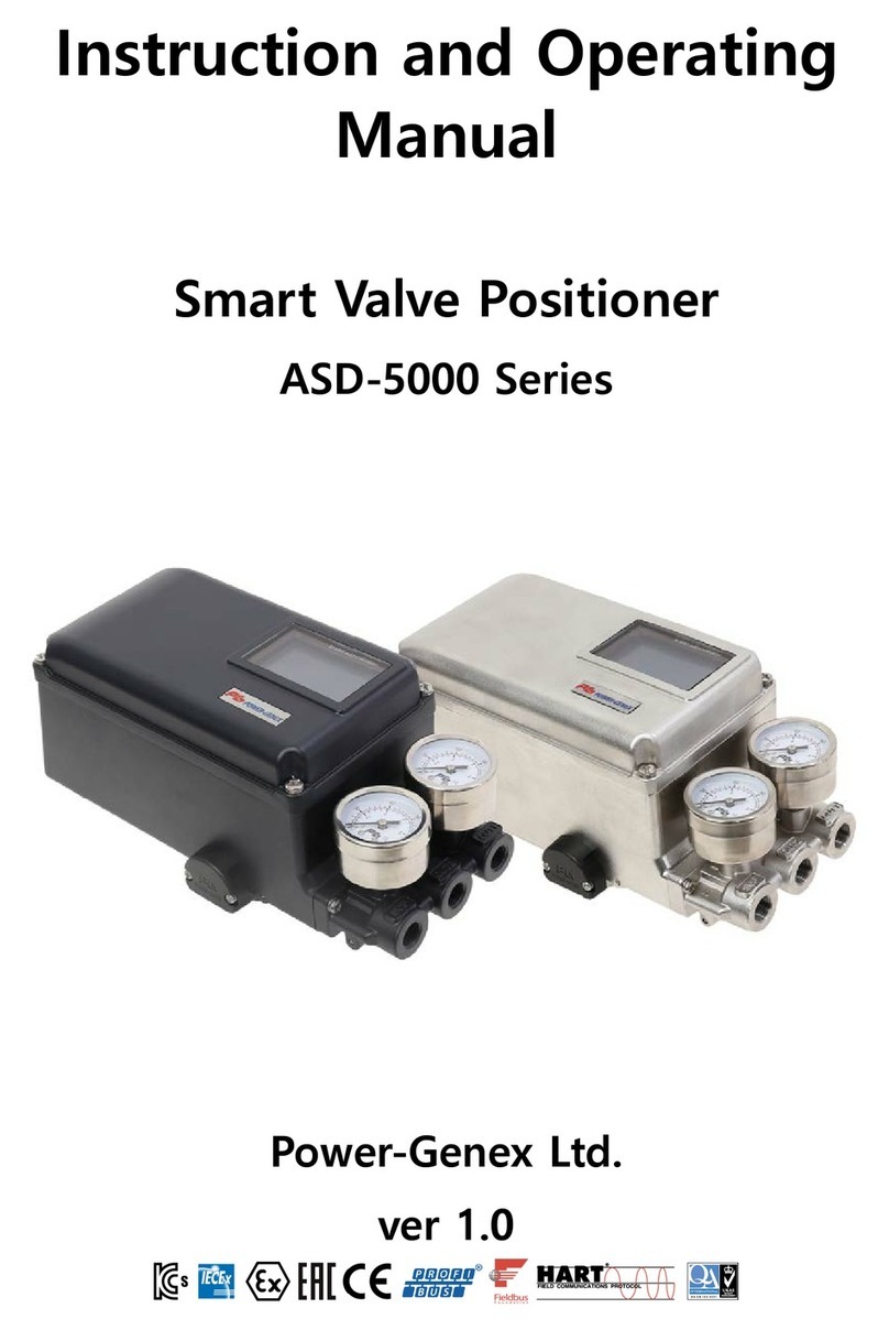
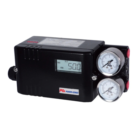
Power-Genex ASD-7 Series Parts list manual

Instruction and Operating
Manual
Smart Valve Positioner
ASD-7 Series
Power-Genex Ltd.
ver 1.0

ASD-7 Series
07 mnl-asd7-en-200923-ver1.0.docxwww.powergenex.com 페이지 2 / 32
Contents
Overview of Structure .......................................................................................................................................................9
2.
Technical data ................................................................................................................................................................... 10
3.
How to order code ......................................................................................................................................................... 11
4.
Descriptions on Nameplate ............................................................................................................................ 12
4.1.
Principle of Operation ................................................................................................................................................... 12
5.
Descriptions of LCD Display and Buttons ............................................................................................................. 13
6.
LCD Display ........................................................................................................................................................... 14
6.1.
Modes of Display ................................................................................................................................... 14
6.1.1.
Multi-lingual Display ............................................................................................................................. 14
6.1.2.
Installation .......................................................................................................................................................................... 15
7.
Mounting onto Linear Actuator .................................................................................................................... 15
7.1.
Installation of Follower Guide ........................................................................................................... 15
7.1.1.
Installation of Feedback Lever and Mounting Bracket ........................................................... 15
7.1.2.
Mounting onto Cast Yoke or Pillar Yoke ...................................................................................... 16
7.1.3.
Mounting on Other Kind of Cast Yoke ......................................................................................... 16
7.1.4.
Mounting on Diaphragm Actuator ................................................................................................. 17
7.1.5.
Installation of Feedback Pin Follower Guide .............................................................................. 17
7.1.6.
Standard Installation ............................................................................................................................. 18
7.1.7.
Operating Angle ..................................................................................................................................... 19
7.1.8.
Proper Installation of Valve stem pin on Feedback Lever ..................................................... 19
7.1.9.
Proper Directions of Installation .................................................................................................... 19
7.1.10.
Mounting onto Rotary Actuator ................................................................................................................... 20
7.2.
The ASD-7 rotary positioner supports NAMUR mounting standard (VDI/VDE 3835,
7.2.1.
IEC 60534-6-2). .................................................................................................................................................... 20
Mounting with Fork Lever Type ....................................................................................................... 21
7.2.2.
Position of Fork Lever ........................................................................................................................... 21
7.2.3.
Re-assembling Multi-size Bracket according to Rotary Actuator ...................................... 22
7.2.4.
Air Connections ................................................................................................................................................................ 23
8.
ASD-7 (linear type) ............................................................................................................................................. 23
8.1.
ASD-7 (rotary type) ............................................................................................................................................ 24
8.2.
Orifice Installment .............................................................................................................................................. 24
8.3.
Auto / Manual ...................................................................................................................................................... 24
8.4.
Electrical Connections ................................................................................................................................................... 25
9.
Earthing ................................................................................................................................................................... 26
9.1.
Measuring Output Signal ................................................................................................................................ 26
9.2.
With mA loop calibrator ..................................................................................................................... 26
9.2.1.
With multi-meter .................................................................................................................................... 26
9.2.2.
Wiring switches .................................................................................................................................................... 26
9.3.
HART Connection ............................................................................................................................................... 27
9.4.

ASD-7 Series
07 mnl-asd7-en-200923-ver1.0.docxwww.powergenex.com 페이지 3 / 32
Profibus PA / Fieldbus Connection .............................................................................................................. 27
9.5.
Maintenance / Service ................................................................................................................................................ 27
10.
Preliminary Check Points ............................................................................................................................... 27
10.1.
Voltage ..................................................................................................................................................... 27
10.1.1.
Electrical Connections ........................................................................................................................ 27
10.1.2.
Pneumatic Connections (see 8.1, 8.2) ......................................................................................... 27
10.1.3.
Supply Air Quality ................................................................................................................................ 27
10.1.4.
Module Parts ...................................................................................................................................................... 27
10.2.
Spare Parts ....................................................................................................................................................................... 29
11.
Dimensions ...................................................................................................................................................................... 30
12.
ASD-7 (linear type) .......................................................................................................................................... 30
12.1.
ASD-7 (rotary type) ......................................................................................................................................... 31
12.2.
REV DATE CHANGE Made by
1.0 20.09.10 작성 김길원

ASD-7 Series
07 mnl-asd7-en-200923-ver1.0.docxwww.powergenex.com 페이지 4 / 32
1-1 Safety Instructions
These safety instructions are intended to prevent hazardous situations and/or equipment damage.
These instructions indicate the level of potential hazard with the labels of “Caution,” “Warning”
or “Danger.” They are all important notes for safety and must be followed in addition to
International Standards (IEC) Note 1), and other safety regulations.
Note 1) IEC 60079-0 IEC 60079-1 IEC 60079-31
EN 60079-0 EN 60079-1 EN 60079-31
Caution
Caution indicates a hazard with a low level of risk which, if not avoided, could result
in minor or moderate injury.
Warning
Warning indicates a hazard with a medium level of risk which, if not avoided, could
result in death or serious injury.
Danger
Danger indicates a hazard with a high level of risk which, if not avoided, will result
in death or serious injury.
Warning
1. The compatibility of the product is the responsibility of the person who designs the equipment or
decides its specifications.
Since the product specified here is used under various operating conditions, its compatibility with
specific equipment must be decided by the person who designs the equipment or decides its
specifications based on necessary analysis and test results. The expected performance and safety
assurance of the equipment will be the responsibility of the person who has determined its
compatibility with the product. This person should also continuously review all specifications of the
product referring to its latest catalogue information, with a view to giving due consideration to any
possibility of equipment failure when configuring the equipment.
2. Only personnel with appropriate training should operate machinery and equipment. The product
specified here may become unsafe if handled incorrectly.
The assembly, operation and maintenance of machines or equipment including our products must be
performed by an operator who is appropriately trained and experienced.
3. Do not service or attempt to remove product and machinery/equipment until safety is confirmed.
1. The inspection and maintenance of machinery/equipment should only be performed after measures
to prevent falling or runaway of the driven objects have been confirmed.
2. When the product is to be removed, confirm that the safety measures as mentioned above are
implemented and the power from any appropriate source is cut, and read and understand the specific
product precautions of all relevant products carefully.
3. Before machinery/equipment is restarted, take measures to prevent unexpected operation and
malfunction.
4. Contact POWER-GENEX beforehand and take special consideration of safety measures if the
product is to be used in any of the following conditions.
1. Conditions and environments outside of the given specifications, or use outdoors or in a place
exposed to direct sunlight.
2. Installation on equipment in conjunction with atomic energy, railways, air navigation, space, shipping,
vehicles, military, medical treatment, combustion and recreation, or equipment in contact with food and
beverages, emergency stop circuits, clutch and brake circuits in press applications, safety equipment or
other applications unsuitable for the standard specifications described in the product catalogue.
3. An application which could have negative effects on people, property, or animals requiring special
safety analysis.
4. Use in an interlock circuit, which requires the provision of double interlock for possible failure by
using a mechanical protective function, and periodical checks to confirm proper operation.
4. Do not open when an explosive gas and dust atmosphere may be present.
5. For enclosure covered with a non-conductive material, propagation brush discharges shall be
avoided
ASD-7 Series
07 mnl-asd7-en-200923-ver1.0.docxwww.powergenex.com 페이지 5 / 32
1-2 Safety Instructions
Caution
1. The product is provided for use in manufacturing industries.
The product herein described is basically provided for peaceful use in manufacturing industries. If
considering using the product in other industries consult POWER-GENEX beforehand and exchange
specifications or a contract if necessary. If anything is unclear, contact your nearest sales branch.
Limited warranty and Disclaimer/Compliance Requirements
The product used is subject to the following “Limited warranty and Disclaimer” and “Compliance
Requirements”. Read and accept them before using the product.
Limited warranty and Disclaimer
1. The warranty period of the product is 1 year in service or 1.5 years after the product is delivered.
Note 2)
Also, the product may have specified durability, running distance or replacement parts. Please consult
your nearest sales branch.
2. For any failure or damage reported within the warranty period which is clearly our responsibility, a
replacement product or necessary parts will be provided. This limited warranty applies only to our
product independently, and not to any other damage incurred due to the failure of the product.
3. Prior to using POWER-GENEX products, please read and understand the warranty terms and
disclaimers noted in the specified catalogue for the particular products.
Note 2) Vacuum pads are excluded from this 1 year warranty.
A vacuum pad is a consumable part, so it is warranted for a year after it is delivered.
Also, even within the warranty period, the wear of a product due to the use of the vacuum pad or failure due to the
deterioration of rubber material are not covered by the limited warranty.
Compliance Requirements
1. The use of POWER-GENEX products with production equipment for the manufacture of weapons of
mass destruction (WMD) or any other weapon is strictly prohibited.
2. The exports of POWER-GENEX products or technology from one country to another are governed
by the relevant security laws and regulations of the countries involved in the transaction. Prior to
the shipment of a POWER-GENEX product to another country, assure that all local rules governing
that export are known and followed.

ASD-7 Series
07 mnl-asd7-en-200923-ver1.0.docxwww.powergenex.com 페이지 6 / 32
1-3 Precautions
Be sure to read before handling.
Operation
Warning
1. Do not operate the positioner outside the specified range as this may cause problems. (Refer to
the specifications.)
2. Design the system to include a safety circuit to avoid the risk of danger should the positioner
suffer failure.
3. Be sure that exterior lead-in wiring to the terminal box is based on the guidelines for explosion-
protection of manufactory electric equipment when being used as a flame proof, explosion proof
construction.
4. Do not remove terminal cover in a hazardous location while the power is on.
5. Covers for the terminal and body should be in place while operating.
6. When using as an intrinsically safe explosion-proof product, do not wire in a hazardous location
while the power is on.
Caution
1. Do not touch the actuator or valve's oscillating section when supply pressure has been added, as
this is dangerous.
2. Make sure fingers do not get caught when mounting and aligning the cam.
Cut off the pressure supply and always release the compressed air inside the positioner and actuator
before performing this work.
3. Always use with the body cover unit mounted.
Moreover, the positioner may not meet degrees of protection IP66 depending on the body cover
mounting conditions. In order to meet degrees of protection IP66, tighten threads using the proper
tightening torques (2.8 to 3.0 N·m).
4. Always flush the pipe's inside before piping to ensure foreign objects such as machining chips do
not enter the positioner.
5. The actuator opening may become unstable when using the booster relay.
6. Always use a ground connection to prevent noise from the input current and to prevent damage
because of static electricity.
7. Use the pressure reading on the supplied pressure gauge as an indication.
8. The supplied pressure gauge's needle will malfunction if the pressure supply to the internal
mechanism or positioner freezes. Ensure that the pressure gauge's internal parts do not freeze if
using the pressure gauge in an operating environment with an ambient temperature of less than
0°C.
For users
Caution
1. Assemble, operate and maintain the positioners after reading the operation manual tho-roughly
and understanding the content.

ASD-7 Series
07 mnl-asd7-en-200923-ver1.0.docxwww.powergenex.com 페이지 7 / 32
1-4 Precautions
Be sure to read before handling.
Handling
Caution
1. Avoid excessive vibration or impact to the positioner body and any excessive force to the
armature, as these actions may cause damage to the product. Handle carefully while transporting
and operating.
2. If being used in a place where vibration occurs, using a binding band is recommended to prevent
broken wires because of the vibration.
3. When exposed to possible moisture invasion, please take the necessary measures. For example, if
the positioner is left onsite for long periods, a plug should be put in the piping port and a body
cover unit fitted to avoid water penetration.
Take measures to avoid dew condensation inside the positioner if exposed to high temperature and
humidity. Take enough measures against condensation especially when packing for export.
4. Keep magnetic field off the positioner, as this affects its characteristics.
Air Suppl
y
Caution
1. Use only dehumidified and dust extracted clean compressed air as the air supply.
2. Use only dehumidified and dust extracted clean compressed clean air as the positioner contains
extrafine orifices such as restrictor and nozzle.
Do not use a lubricator.
3. Do not use compressed air containing chemicals, organic solvents, salinity or corrosive gases, as
this may cause malfunction.
4. When operating below the freezing point, protect the positioner from freezing.
Operating Environment
Caution
1. Do not operate in locations with an atmosphere of corrosive gases, chemicals, sea water, or where
these substances will adhere to the regulator.
2. Do not operate out of the indicated operation temperature range as this may cause damage to
electronic parts and seal materials to deteriorate.
3. Do not operate in locations where excessive vibration or impact occurs.
4. If the body cover is being installed in a place where the body cover is exposed to direct sunlight,
the use of a standard body cover without the LCD window is recommended.

ASD-7 Series
07 mnl-asd7-en-200923-ver1.0.docxwww.powergenex.com 페이지 8 / 32
1-5 Precautions
Be sure to read before handling.
Maintenance
Warning
1. After installation, repair or disassembly, connect compressed air and conduct tests
to confirm appropriate function and leakage.
Do not use the positioner when noise from the bleeder sounds louder compared with the initial
state, or when it does not operate normally. If these occur, check immediately if assembled and
mounted correctly.
Never modify electrical construction to maintain explosion-proof construction.
Warning-Potential electrostatic charging hazard
1. The non-metallic parts incorporated in the enclosure of this equipment may
generate an ignition capable level of electrostatic charge. Therefore particularly
when it used for applications that specifically require Group IIC, EPL Ga
equipment, the equipment shall not be installed in a location where the external
conditions are conductive to the build-up of electrostatic charge on such surfaces.
Additionally, the equipment shall only be cleaned with a damp cloth.
2. The enclosure contains aluminum and is considered to present a potential risk of
ignition by impact or friction. Care must be taken during installation and use to
prevent impact or friction. Particularly, it must not be used for applications that
specifically require EPL Ga equipment.
Caution
1. The insulation between an intrinsically safe circuit and a frame of the equipment is
not capable of withstanding a 500V dielectric strength test as defined in CI.6.3.12 of
EN 60079-11:2007. This shall be taken into account during installation.
2. the earthing of enclosure is necessary to maintain Intrinsic Safety because the
insulation between an intrinsically safe circuit and a frame of the equipment is not
capable of withstanding a 500V dielectric strength test. There are two earthing
points on the equipment. One is provided as an internal earthing point inside rear
cover of the equipment for attaching of a cable screen. The other is provided as an
external earthing point on the left side of the enclosure. Their cross-sectional areas
should be capable of carrying the maximum possible current of the
equipment.(Generally, an insulated wire having a cross-sectional area of at least
4mm2 is recommended) The cable should be fitted with a spilt ring lock washer to
minimize the risk of self-loosening and is of suitable construction for securing of
conductors of cross sections up to 4mm2.

ASD-7 Series
07 mnl-asd7-en-200923-ver1.0.docxwww.powergenex.com 페이지 9 / 32
Overview of Structure
2.
ASD-7 positioner consists of the following parts.
• Electronic card with microprocessor, HART modem and LCD
• MPS for position feedback
• Pilot valve, torque motor, pressure gauge and block
Button cover open
Names of External Parts
1 LCD 7 Mode button 13 Positioner body
2 Gauge block 8 Enter button 14 Positioner cover
3 Out 2 gauge 9 Ground 15 Button cover
4 Out 1 gauge 10 Blind plug (or cable gland) 16 Junction cover
5 Up button 11 Terminal
6 Down button 12 Vent cover

ASD-7 Series
07 mnl-asd7-en-200923-ver1.0.docxwww.powergenex.com 페이지 10 / 32
Technical data
3.
1. Input
6. Enclosure
Standard
Material :
Aluminum die-cast + Epoxy painted
Supply power :
4 to 20mA, Loop powered
316 Stainless steel housing
Protection class :
IP66
Min. :
3.6mA
Pneumatic connections :
PT 1/4
Load voltage at 20mA :
6.8V
NPT 1/4
Impedance at 20mA :
340 Ω
Electrical connections :
NPT 1/2
HART Communication ver. 7
M20 x 1.5
- Without advanced diagnostics
Load voltage at 20mA :
7.8V
Weight :
3.5 kg – Aluminum die-cast
Impedance at 20mA :
390 Ω
7 kg – Stainless steel 316
- With advanced diagnostics (with 4 pressure sensor)
Load voltage at 20mA :
9.5V
7. Hazardous Area Approvals
Impedance at 20mA :
475 Ω
IECEx
Flameproof, Ex db IIC T6 / T5 Gb
Dustproof, Ex tb IIIC T80 / T95 Db
Profibus PA & FOUNDATION fieldbus
A
TEX
Flameproof, Ex db IIC T6 / T5 Gb
Dustproof, Ex tb IIIC T80 / T95 Db
Supply power :
Bus power 9 – 32VDC
KCs
Flameproof, Ex db IIC T6 / T5 Gb
Dustproof, Ex tb IIIC T80 / T95 Db
Current Consumption :
Profibus - 15mA
CCC
Flameproof, Ex d IIC T6 / T5 Gb
Dustproof, Ex td a21 IIIC T80 / T95 Db
FOUNDATION fieldbus - 16mA
8. Environmental influences
2. Output
A
mbient temperature :
-40 ~ +70°C (T6), -40 ~ +80°C (T5)
Range :
0 – 7 bar (0 – 100 psi)
Operating temperature of LCD : -20 to 80
℃
( -xx to 176
℉
)
A
ir consumption :
2.5 L.P.M
Vibration :
2G, 5 to 400 Hz
at 1.4 bar (20 psi) supply pressure
Humidity :
The dew point should be at least 10
℃
3.0 L.P.M
Lower than the temperature of this device.
at 6 bar (90 psi) supply pressure
A
ir Capacity :
250 L.P.M
9. Feedback option
at 1.4 bar (20 psi) supply pressure
Position Transmitter (Output signal)
300 L.P.M
Output signal :
4-20mA, 2wire
at 6 bar (90 psi) supply pressure
Supply voltage :
12-30VDC
Load Limitation :
0 – 1000 Ω (Normally 650Ω at 24VDC)
3. Air Supply
Linearity
± 0.5%
Instrument air :
free of oil, water and dust acc. to
Limit switches – Software program limits
DIN/ISO 8573-1 pollution and oil
Type :
2 x software program limits
content according to Class 3
Rating :
24VDC
Supply pressure :
1.4 to 7 bar (20 to 100 psi)
Limit switches – Micro switches
Type :
2 x SPDT
4. Applicable actuato
r
Rating :
10A @ 220VAC
Operating type :
Linear, Rotary, Remote
Contact :
Silver alloy
A
cting type :
Single, Double
A
mbient temperature :
-25 - 85
℃
A
ction :
direct action(DA), reverse action(RA)
Limit switches – P&F sensor (SJ2-SN)
Linkage type
Type :
NAMUR NC
Travel range :
Linear : 10 – 120 mm
Supply voltage :
Nominal 8.2VDC (5 – 11 VDC)
Rotary : 30 – 120 rotation angle
Current consumption :
Target not detected > 3mA
Linkage-less type
Target detected < 1mA
Travel range :
Linear : 10 – 120 mm
A
mbient temperature :
-40 - 100
℃
Rotary : 30 – 120 rotation angle
Remote : 3, 5, 10, 15, 20, 30M
10. Mounting bracket
※
Other travel range on request
Linear type
IEC 60534-6-1
Rotary type
IEC 60534-6-2
5. Characteristic
Linearity
< ±0.5% F.S
Sensitivity
< ±0.3% F.S
Hysteresis
< ±0.3% F.S
Repeatability
< ±0.2% F.S
Performance characteristic
Linear, Shape (EQ%, Quick), User set

ASD-7 Series
07 mnl-asd7-en-200923-ver1.0.docxwww.powergenex.com 페이지 11 / 32
How to order code
4.
Model classification code or ordering information or type designation or model schedule or model numbering system
① ② ③ ④ ⑤ ⑥ ⑦ ⑧ ⑨ ⑩ ⑪
ASD-7 Series positioner
ASD - 7 X
x x - F x x x
x
x
x
x
1 Body material
Aluminum die-cast
stainless steel 316
0
1
2. Actuator operation
Linear type
Rotary type
0
1
3 Feedback type
Linkage type
Linkage-less type
Remote type
0
1
2
4. Hazardous Area
& Protection
Flameproof Ex db IIC Gb T6 / T5
Dustproof Ex tb IIIC T80 / T95 Db IP66
F
5. Feedback size
Linkage
type
Linear type
(ASD-7x00)
Stroke 10 –
60mm
Stroke 10 - 120mm
*Order on request
B
C
Rotary type
(ASD-7x10)
Fork lever
NAMUR shaft
F
N
Linkage
-less
Type
Linear type
(ASD-7x01)
Stroke 10 –
120mm
*Order on request
B
Rotary type
(ASD-7x11)
M6 Connector
M8 Connector
6
8
6. Gauge (Out1, Out2)
6 bar (90 psi)
10bar (150 psi)
1
2
7. Options
None
Position Transmitter (4-20mA)
Advanced diagnostics + position transmitter
N
O
A
8. Limit switches
None
2 x Software Switches (Alarm limit)
2 x Micro switches (SPDT)
2 x P&F sensors
N
L
S
P
9. Communication
None
HART Communication
Profibus PA
FOUNDATION FIELDBUS
N
H
P
F
10. Connection Threads
PT(Rc) 1/4 - NPT 1/2
NPT 1/4 –
NPT 1/2
NPT 1/4 –
M20x1.5
PT(Rc) 1/4 –
M20x1.5
3
4
5
6
11. Mounting Bracket
None
Linear bracket / IEC 60534-6-1
Rotary type / IEC 60534-6-2
N
L
R
12. Remote Cable
(only for ASD-72xx)
3, 5, 10, 20, 30M
Order example
ASD - 7 0
0 0 -
F
N 2 O
N
H
4
R

ASD-7 Series
07 mnl-asd7-en-200923-ver1.0.docxwww.powergenex.com 페이지 12 / 32
Descriptions on Nameplate
4.1.
Model No : Model number and options are described.
Input signal : Current input signal is described. 4~20mA current is used. Inquire the head office or
the agents if other special input signal is required.
Electrical Connections : Conduit connection thread mark
Pneumatic Connections :
Pneumatic connection thread mark
Supply air (Max.) : Maximum operating pressure range indication
Ambient Temp. : ambient temperature
Serial number / date: A serial number and a manufacturing date for tracking are described.
Certificate No :
Ex db IIC T6 / T5 Gb - Ex tb IIIC T80℃ / T95℃ Db
CE XXXX / INERIS ATEX XXXX / IECEx KTL 21.0034X / 21-KB2BO-XXXX
WARNING :
POTENTIAL ELECTROSTATIC CHARGING HAZARD SEE INSTRUCTION.
DO NOT OPEN WHEN AN EXPLOSIVE GAS ATMOSPHERE MAY PRESENT.
Principle of Operation
5.
If 4-20 mA input signal is supplied, the micro-processor compares input signal with position
feedback and sends control signal to the I/P converting module. Pneumatic signal from the I/P
converting module operates the valve and the valve stays at the desired position.
Torque Motor

ASD-7 Series
07 mnl-asd7-en-200923-ver1.0.docxwww.powergenex.com 페이지 13 / 32
Descriptions of LCD Display and Buttons
6.
1 Input signal (current)
2 Input signal (%)
3 Present value position (%)
4 Present value position (by colored bar)
5 NAMUR NE107 diagnostic
6 HART Communication status
7 Status of software limit switches
8 Status of control (stable or unstable)
9 Up button
10 Down button
11 Mode button
12 Enter button
Press "Mode button for 5 seconds ㆍ Quick auto-calibration
Press “Up” button for 5 seconds ㆍ GROP-gain adjustment
Press “Down” button for 5 seconds ㆍ Span adjustment
Press “Enter” button ㆍ Ambient temperature (℃)
Display of input or output ㆍ mA, %
Main parameters ㆍ See positioner parameter (6.1.3)
Display mode ㆍ Selection of mA, % or in reverse way with values shown
(Ex. Reverse : 20% shown → 80% shown)
HART communication ㆍ HART communication
UP ㆍ UP button
DOWN ㆍ DOWN button
MODE ㆍ Selection of running mode
ㆍ Selection of parameter group or parameter
ENTER ㆍ Save of setting values

ASD-7 Series
07 mnl-asd7-en-200923-ver1.0.docxwww.powergenex.com 페이지 14 / 32
LCD Display
6.1.
Modes of Display
6.1.1.
Focusing on target value and present value
(basic display)
Focusing on present value
After rotated by 90 / 270°
Showing all data
Showing TV and PV by graph Showing trand deviation (±5%)
Multi-lingual Display
6.1.2.
English 한국어 中國語

ASD-7 Series
07 mnl-asd7-en-200923-ver1.0.docxwww.powergenex.com 페이지 15 / 32
Installation
7.
Be sure to install the air filter regulator before the positioner and check a supply air
pressure required to move the valve.
Mounting onto Linear Actuator
7.1.
Installation of Follower Guide
7.1.1.
① Follower guide
② Clamp plate
③ Screws(M6)
④ Valve yoke
⑤ Valve stem
Installation of Feedback Lever and Mounting Bracket
7.1.2.
Mounting bracket for ASD-7 positioner is designed to support IEC 60534-6-1.
① Mounting bracket
② Screws(M8)
③ Feedback lever
④ ASD-7 positioner
⑤ Feedback pin

ASD-7 Series
07 mnl-asd7-en-200923-ver1.0.docxwww.powergenex.com 페이지 16 / 32
Mounting onto Cast Yoke or Pillar Yoke
7.1.3.
< Cast yoke type > < Pillar yoke type >
① Cast yoke
② Mounting bracket
③ Screws(M8)
④ U-bolts
⑤ Pillar yoke
Mounting on Other Kind of Cast Yoke
7.1.4.
< Cast yoke type >
① Cast yoke
② Mounting bracket
③ Screws(M8)

ASD-7 Series
07 mnl-asd7-en-200923-ver1.0.docxwww.powergenex.com 페이지 17 / 32
Mounting on Diaphragm Actuator
7.1.5.
Feedback Levers
"A" type: 8 ~ 30mm stroke
"B" type: 8 ~ 70mm stroke
"C" type: 8 ~ 130mm stroke
Installation of Feedback Pin Follower Guide
7.1.6.

ASD-7 Series
07 mnl-asd7-en-200923-ver1.0.docxwww.powergenex.com 페이지 18 / 32
Standard Installation
7.1.7.
① Supply air directly to the actuator, adjust the air filter regulator and set air when the valve
reaches to 50% stroke.
② Install the feedback pin at around 30% higher point of the stroke indicated on the feedback
lever than the required stroke of the control valve and fix with a screw tightly. For example,
Control valve stroke Stroke indicated on feedback lever
15mm 15mm
20mm 20mm
30mm 30mm
③ Install the feedback lever horizontally at 50% stroke position.
④ If the feedback lever is not installed horizontally, move the mounting bracket up and down
little by little so that it can be positioned horizontally.
⑤ Fix the mounting bracket with screws (M8).
⑥ Connect air lines between the ASD-7 linear positioner and the actuator and supply air to the
positioner and perform auto-calibration by pushing Mode button for 5 seconds.
⑦ The operating angle from 0% to 100% stroke should be within the range of ±30°. In case of
the over-range of 30°, move the valve stem pin to left or right and make the ASD-7 linear
positioner stay within the operating angle of ±30°.
Make sure that the ASD-7 linear positioner works within the operating range of ±30°.
See the below pictures. Otherwise, the error message of ‘MONT’ appears on LCD and
the auto-calibration process fails. Take action as advised in the above ⑦ and get the
ASD-7 linear positioner feedback lever positioned horizontally at 12mA (50%).

ASD-7 Series
07 mnl-asd7-en-200923-ver1.0.docxwww.powergenex.com 페이지 19 / 32
Operating Angle
7.1.8.
Proper Installation of Valve stem pin on Feedback Lever
7.1.9.
Proper Directions of Installation
7.1.10.

ASD-7 Series
07 mnl-asd7-en-200923-ver1.0.docxwww.powergenex.com 페이지 20 / 32
Mounting onto Rotary Actuator
7.2.
The ASD-7 rotary positioner supports NAMUR mounting standard (VDI/VDE 3835, IEC
7.2.1.
60534-6-2).
① ASD-7 positioner ② Multi-size bracket ③ Rotary pneumatic actuator
Assemble the multi-size bracket to the ASD-7 rotary positioner with 4 pcs M6 screw. The
multi-size bracket is assembled for 80x30x20mm as standard at the factory. If you have
other size bracket, see ‘7.2.4 Re-assembling Multi-size Bracket according to Rotary
Actuator.
Mount the ASD-7 rotary positioner onto the rotary pneumatic actuator with 4 pcs M5
screw.
Connect air lines between the ASD-7 rotary positioner and the rotary pneumatic actuator.
Perform auto-calibration by pushing MODE button for 5 seconds.
Make sure that the ASD-7 rotary positioner works within the operating range indicated
on the bottom. See the below pictures. Otherwise, the error message of ‘MONT’
appears on LCD and the auto-calibration process fails.
Table of contents
Other Power-Genex Valve Positioner manuals

Power-Genex
Power-Genex SS3SL Series Parts list manual

Power-Genex
Power-Genex SS2L Series Parts list manual

Power-Genex
Power-Genex SS2L Series User manual

Power-Genex
Power-Genex PPR Series User manual

Power-Genex
Power-Genex ASD-5000 Series Parts list manual

Power-Genex
Power-Genex SSL Series User manual

Power-Genex
Power-Genex SS3L Series Parts list manual
Popular Valve Positioner manuals by other brands

Spirax Sarco
Spirax Sarco EP500 Installation and maintenance instructions

rotork
rotork YT-3300 Series product manual

Baker Hughes
Baker Hughes Masoneilan SVI FF quick start guide

Becker
Becker HPP-SB instruction manual

Baker Hughes
Baker Hughes Masoneilan 51 Series instruction manual

Badger Meter
Badger Meter RCV SRI990 quick start guide