manuals.online logo
Brands
  1. Home
  2. •
  3. Brands
  4. •
  5. ITT
  6. •
  7. Valve Positioner
  8. •
  9. ITT GC31 Instructions for use

ITT GC31 Instructions for use

Page 1 of 8 GC31-IOM Rev. B 07/19
Enidine / Conoflow
105 Commerce Way
Westminster, SC 29693
Tel: (864) 647-9521
Fax: (864) 647-7993
INSTRUCTION AND MAINTENANCE MANUAL
GC31 COMMANDAIRE POSITIONER
PRINCIPLE OF OPERATION
The COMMANDAIRE Model GC31 positions the actuator by applying a sufficient air pressure in the load chamber to overcome the cushion load
pressure, plus any external forces or load acting on the actuator stem. An increase in air signal pressure acts on a diaphragm and moves the yoke to
the right. This closes an exhaust port and opens the supply valve. Air flows through the supply valve into the load chamber and drives the piston
downward, extending the actuator stem. Piston movement extends the range spring, which in turn, causes the bellcrank to rotate counterclockwise.
This rotation of the bellcrank exerts a force against the yoke pin and moves the yoke towards a balanced position. A decrease in instrument air pressure
reverses the procedure, closing the supply valve and opening the exhaust port. This vents the pressure in the load chamber to atmosphere and allows
the cushion load pressure to move the piston and retract the actuator stem.
WARNING
Conoflow products are designed and manufactured using
materials and workmanship required to meet all applicable
standards. The use of these products should be confined to
services specified and/or recommended in the Conoflow
catalogs, instructions, or by Conoflow application engineers.
To avoid personal injury or equipment damage resulting from
misuse or misapplication of a product, it is necessary to select
the proper materials of construction and pressure-temperature
ratings which are consistent with performance requirements.
Page 2 of 8 GC31-IOM Rev. B 07/19
SUPPLY PRESSURE (20 to 100 psi / 138 to 690 kPa)
A regulated and filtered air supply should be used. A Conoflow
model FR95 Airpak Filter Regulator or equal is recommended.
ZERO ADJUSTMENT
Zero adjustment can be made by turning the zero adjust
coupling, located on top of the headplate assembly (2), clockwise
or counterclockwise. Connect supply and instrument air to the
positioner. Set the instrument signal to the 0% value (e.g. 3 psi
(21 kPa) for a 3-15 psi (21-143 kPa) range). Turn the zero adjust
coupling to bring the actuator slightly off the fully retracted
position. The starting point may then be checked by reducing the
instrument signal below the 0% value and then slowly increasing
it. As the 0% input signal is reached, extension of the actuator
stem plus an audible increase in the air flow through the
positioner should be observed.
Next, increase the instrument signal to the 100% value (e.g. 15
psi for a 3-15 psi (103 kPa for a 21-103 kPa range). Verify that
the actuator stem moves to the fully extended position.
Set the instrument signal to the 50% value. Using a suitable
measuring device, such as a scale, verify the actuator stem has
extended to 50% of full stroke.
SPAN
Positioner span determines the control range. A positioner with a
3-15 psi (21 to 103 kPa) range has a 12 psi (83 kPa) span and is
set with a 3 psi (21 kPa) start point (retracted position).
Positioner span has been factory calibrated as specified.
Instrument signals of 3-9, 3-15 and 6-30 psi (21-62, 21-103, and
41-207 kPa) are available. For field changes, refer to page 4 of
this manual and Range Spring Manual C-8053.
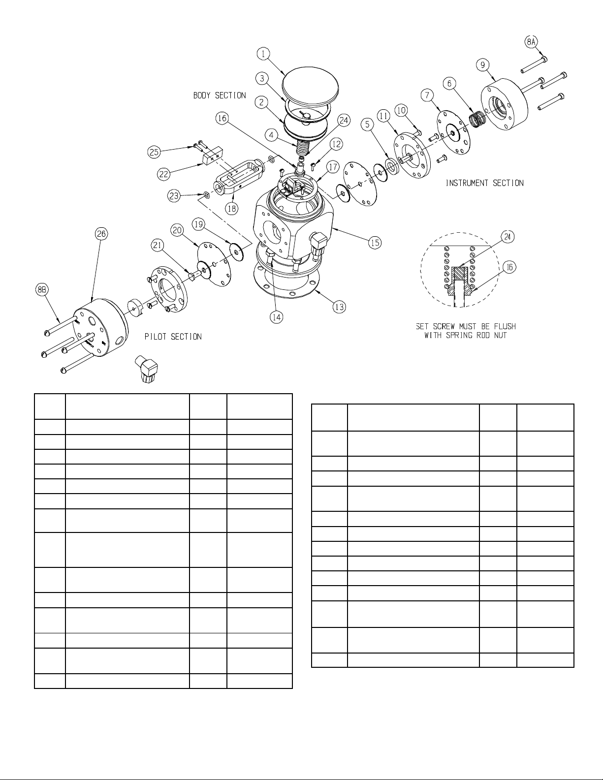
REMOVING POSITIONER FROM ACTUATOR
WARNING: Shut off supply and instrument
air and assure all pressure is bled before
performing any maintenance.
Piston (or diaphragm) should be in the fully retracted position.
Disconnect tubing and verify all air is bled from the actuator.
Remove cap (1) and Spirolox ring (3) from positioner so the head
plate assembly (2) can be lifted out. Loosen setscrew (24) using
a 1/8” hex key wrench, and remove spring rod nut (16). Remove
the six cap screws (14) and lift positioner from the actuator.
INSTALLING POSITIONER ON ACTUATOR
The Model GC31 positioner is designed for actuators having a 2
¼” dimension between the lower face of the range spring nut
(8D) and the positioner mounting flange with the actuator stem in
a retracted position. See dimensions on Page 5.
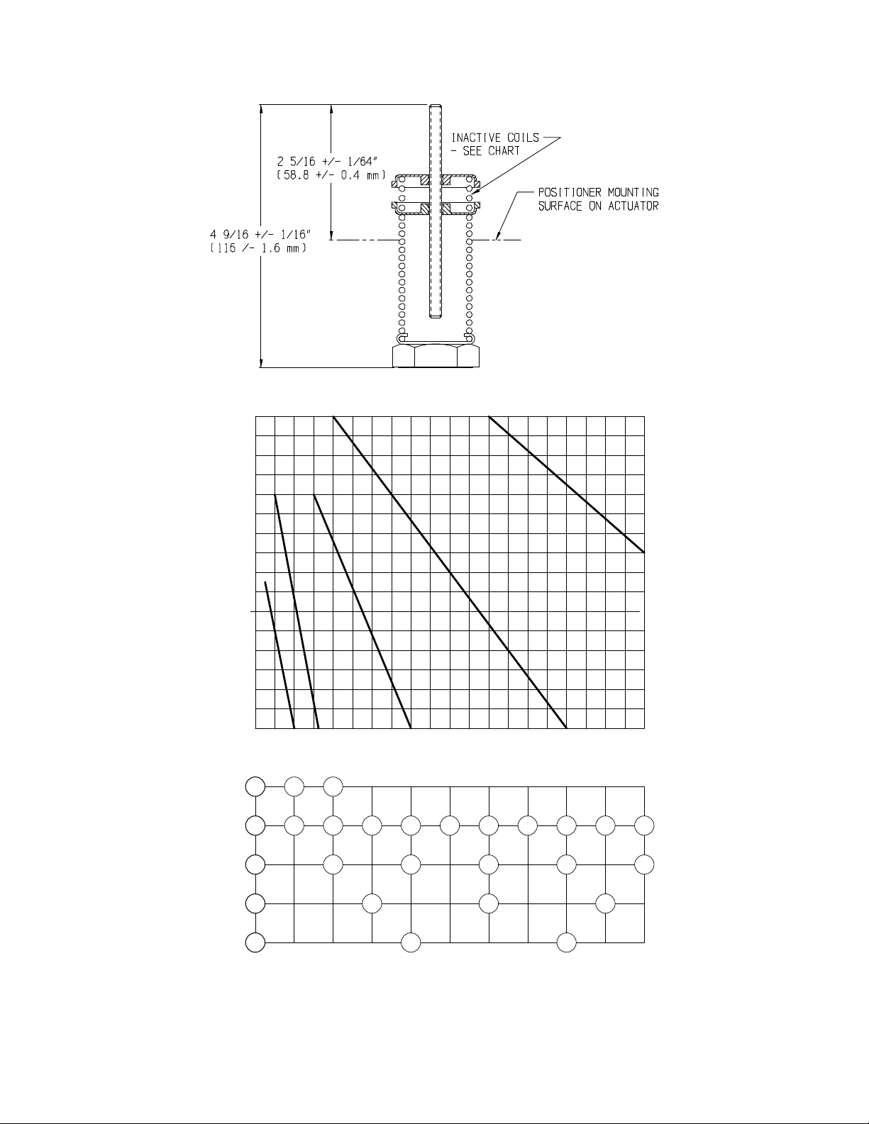
The range spring (8C) is adjusted and set at the factory for the
proper range and spring rod (8A) extension, as shown on page 6.
With the actuator stem in the fully retracted position and the
spring rod nut (16) removed from the spring rod (8A), thread the
spring nut assembly (8D) onto the actuator stem. Hold the range
spring assembly in a vertical position without applying any
tension to the range spring (8C). Measure the distance between
the positioner mounting surface on the actuator (without gasket)
and the top of the spring rod (8A). This distance must be 2-5/16”
+/- 1/64” (58.75 +/- 0.41 mm) for proper operation of the
positioner (see page 4). If adjustment is necessary, grasp the
lower spring clip (8B) and range spring (8C) while retightening
the upper clip securely. Measure the 2-5/16” (58.75) dimension
again to make sure it is correct. Be sure the actuator stem is fully
retracted when making this measurement.
Remove the cap (1) from the positioner and, using a small
screwdriver, remove the Spirolox ring (3). Pull out the positioner
headplate assembly (2) and set it aside. The zero spring (4)
should also be attached to the headplate assembly. If not,
remove it also. Place the gasket (13) and the positioner on the
actuator, guiding the spring rod (8A) through the hole in the bell
crank (17). Install the six hex head cap screws (14) that secure
the positioner to the actuator.
Adjust the set screw (24) in the spring rod nut (16) such that the
head of the screw is flush with the top of the nut. Install this
assembly onto the spring rod (8A) finger tight. Hold the spring
rod nut (16) with a wrench to prevent rotation, and tighten the set
screw (24) securely. It is important to make sure that the spring
rod nut (16) does not turn while tightening the set screw in order
to maintain calibration of the range spring assembly.
Insert the zero spring (4) onto the headplate and install the
headplate assembly (2). Make sure the zero spring (4) is
properly centered on the spring rod nut (16) when inserting this
assembly. Replace the Spirolox ring (3). Connect the
necessary piping. Proceed with the zero adjustment procedure
previously outlined. When complete, replace the cap (1).
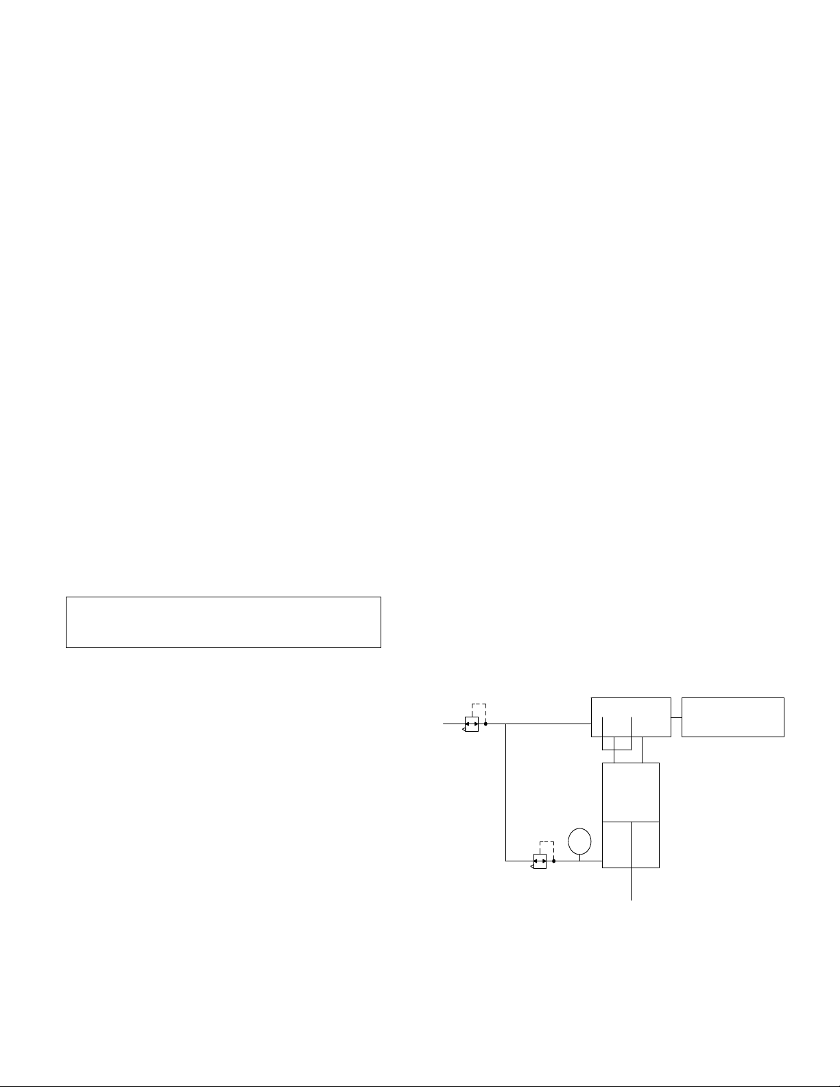
SYSTEM CONFIGURATIONS
The operation of the Commandaire GC31 positioner with an
actuator may be configured differently, depending on the needs
of the system. The following schematics illustrate several
common configurations for the model GC31 with a piston
actuator.
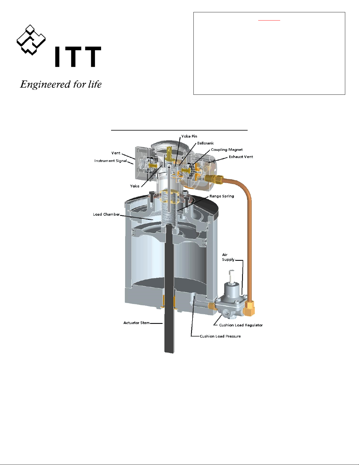
DOUBLE ACTING ACTUATOR WITH CUSHION LOAD
The use of a suitable cushion load regulator, such as the
Conoflow GH04, will drive double acting actuator operation.
Actuator
CG31 Positioner Instrument Signal
(manual or transducer)
Air Supply
Filter Regulator
P
GH04 Cushion
Load Regulator
Page 3 of 8 GC31-IOM Rev. B 07/19
FULL REVERSAL OPERATION
When used with a Conoflow model GH232T reversing relay
rather than a cushion load regulator, the GC31 positioner will
provide maximum actuator stem thrust loads in extension and
retraction. The GH232T reversing relay must be connected as
shown in the schematic below:
Actuator
GH232T
Reversing
Relay
CG31 Positioner Instrument Signal
(manual or transducer)
Air Supply
Filter Regulator
OPERATING CHECKS
With positioner installed and adjusted in accordance with the
preceding instructions, the actuator stem should react to
variations in input control signal. By removing the cap (1) and
depressing the zero adjust coupling of the headplate assembly
(2) while the control signal is applied, step excursions of the stem
should take place and the stem should return accurately to its
previous position. If the actuator does not appear to function
correctly, check to make sure that the filtered supply pressure
and cushion loading pressure are set correctly.
RANGE SPRING INFORMATION AND APPLICATIONS
AIRLOCK OPERATION
The addition of an airlock system drives the actuator stem to
retract when an air supply failure occurs. The airlock system
consists of a volume tank (pressure vessel) and a check valve
that drives the cushion load regulator and lifts the actuator piston
when the air supply fails. This action will retract the actuator
stem in the event of an air supply failure.
Actuator
CG31 Positioner Instrument Signal
(manual or transducer)
Air Supply
Filter Regulator
P
GH04 Cushion
Load Regulator
Pressure
Vessel
Check Valve
OTHER CONFIGURATION POSSIBILITIES
A shut off valve can be piped between the load chamber and
cushion load volumes for manual operator applications. Opening
the valve will equalize the pressure. This allows manual
operation override of the positioner when this valve is open, and
instrument signal / positioner operation when the valve is closed.
Optional tapped exhaust ports on the pilot and instrument
connections are also available for use with non-corrosive gas
operation.
Example: Basic No.
Stem Nut Assembly
Stroke Length Color
GJ800 4 Y
In this example, part number GJ8004Y would be a range spring
assembly for the GB52 with a yellow spring. Refer to manual
C-8053 for specific ordering information.
Table 1: Stem Nut Selection
STEM
NUT
ASSY NO. THREAD ACTUATOR CYLINDER
SIZE
1 3/8-24 GB50 3"
3 1/2-20 GB51 4"
4 9/16-18 GB52 6"
5 5/8-18 GB53 8"
6 7/8-14 GB54 10"
Page 4 of 8 GC31-IOM Rev. B 07/19
See manual C-8053 for full description of range spring configurations
0
0
0
0
0
1
1
1
1
2
2345678910
4
2
2
3 4
2
3
5
TRAVEL IN INCHES FOR SPAN REQUIRED
NOTE: For travels greater than 10" (254mm) consult factory
3
4
6
12
24
4
5
6
7
8
9
10
11
12
13
14
15
16
17
18
19
20
RED
BLUE
GREEN
WHITE
YELLOW
SPAN (PSI)
RANGE SPRING ADJUSTMENT CHART
NUMBER OF INACTIVE COILS
Page 5 of 8 GC31-IOM Rev. B 07/19
Notes:
1. All connections are ¼” NPT unless otherwise noted.
2. When ordering, specify model, range and stroke.
3. For additional piping schematics, see A50-48
4. Vent ports can be tapped ¼” NPT for gas service.
Page 6 of 8 GC31-IOM Rev. B 07/19
Item
No. Description Qty.
Req'd Part No.
1 Top Cap 1 G6025969
2 Head Plate Assembly 1 G6027130
3 Spirolox Ring 1 G6004691
4 Zero Spring 1 G6025811
5 Magnet 1 G6078307
6 Instrument Spring 1 G6026843
7(1) Instrument Diaphragm
Assy 1 G6026652
8A Fillister Head Machine
Screw 10-32 x 1-1/2"
Long 4 G6900063
8B Round Head Machine
Screw10-32 x 2" Long 4 G6900659
9 Instrument Cap 1 G6387170
10(5) Flat Head Machine Screw
8-32 x 1/2" Long 6 G6900574
11(5) Spacer 2 G6026785
12 #4 Self Tapping Screw
3/8" Long 3 G6900545
13(1) Gasket 1 G6001762
Item
No. Description Qty.
Req'd Part No.
14 Hex Head Capscrew
1/4-20 x 5/8" Long 6 G6900095
15 Body 1 G6387173
16 Spring Rod Nut 1 G6025803
17 Flexure Ring Assembly
(Bellcrank) 1 G6025753
18 Yoke Assembly 1 G6026579
19(5) Diaphragm Plate 4 G6026686
20(1,5) Diaphragm 2 G6026553
21(5) Diaphragm Screw 2 G6026546
22 Inside Stop Block 1 G6026538
23(1,5) O-Ring 2 G6076608
24 Socket Set Screw (Dog
Point) 1/4-28 x 1/4" Long 1 G6900113
25 Round Head Machine
Screw 4-40 x 1/2" Long 2 G6900007
26 Pilot Assembly 1 G6027148
SEE NOTES ON PAGE 7
Page 7 of 8 GC31-IOM Rev. B 07/19
Notes:
1. Recommended spare parts can be purchased
individually, or as a spare parts kit, under part number
G6385464, Spare Parts Kit GC31 (Consists of items 7,
13, 20 and 23).
2. When ordering spare parts, specify complete catalog
no., item no., and part no. This will permit positive
identification and rapid handling of order.
3. For body assembly, order item G6026504 (Consists of
items 10 through 12, and items 15 through 25).
4. For tapped exhaust, use
a. G6026819 for item 9
b. G6027155 for item 26
5. Diaphragms and spacers are symmetric about body
section and are not all identified by item no.s
6. Pilot section and instrument cap are machined bar parts
(previously used to be castings). Pilot Assembly (26)
requires longer (2 inch) screws. Pilot assembly and
screws may be ordered by part no. GC31-PILOT
Page 8 of 8 GC31-IOM Rev. B 07/19
This Page Intentionally Left Blank

Popular Valve Positioner manuals by other brands

EBRO ARMATUREN SBU IO-Link quick guide

EBRO ARMATUREN

EBRO ARMATUREN SBU IO-Link quick guide

Samson FOUNDATION 3730-5 Configuration manual

Samson

Samson FOUNDATION 3730-5 Configuration manual

Econ 3300 Series Installation and operating manual

Econ

Econ 3300 Series Installation and operating manual

Micronix PPS-20 Series Reference manual

Micronix

Micronix PPS-20 Series Reference manual

SMC Networks IP8001 Series Operation manual

SMC Networks

SMC Networks IP8001 Series Operation manual

Flowserve D20 Series Installation operation & maintenance

Flowserve

Flowserve D20 Series Installation operation & maintenance

PI L-509 user manual

PI

PI L-509 user manual

Dresser Masoneilan 8013 Series instructions

Dresser

Dresser Masoneilan 8013 Series instructions

Power-Genex SS2L Series Instructions and operating manual

Power-Genex

Power-Genex SS2L Series Instructions and operating manual

Samson 4763 Mounting and operating instructions

Samson

Samson 4763 Mounting and operating instructions

RTK SR-3300 Installation and operating instructions

RTK

RTK SR-3300 Installation and operating instructions

Samson 3785 series Mounting and operating instructions

Samson

Samson 3785 series Mounting and operating instructions

GE SVI II AP-2 quick start guide

GE

GE SVI II AP-2 quick start guide

Leuze BPS 8 operating instructions

Leuze

Leuze BPS 8 operating instructions

Samson 3731-5 Mounting and operating instructions

Samson

Samson 3731-5 Mounting and operating instructions

gefran POS-MINI SIEIDrive instruction manual

gefran

gefran POS-MINI SIEIDrive instruction manual

Westlock ICOT 5400 Technical manual

Westlock

Westlock ICOT 5400 Technical manual

Samson 3730-2 Mounting and operating instructions

Samson

Samson 3730-2 Mounting and operating instructions

manuals.online logo
manuals.online logoBrands
  • About & Mission
  • Contact us
  • Privacy Policy
  • Terms and Conditions

Copyright 2025 Manuals.Online. All Rights Reserved.