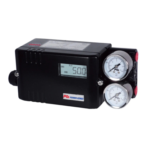
Power-Genex SS2L Series User manual

사용 설명서
Smart Valve Positioner
SS2L / SS2R 시리즈
< Software Ver. V21C >
파워제넥스㈜

SS2L / SS2R 시리즈
www.powergenex.com 2
목차
1. 매뉴얼 개요 3
11.5.5 [ZERO] 제로값 변경
2. 제품 외형 8
11.5.6 [PID] PID-게인 39
3. 제품 사양 9
11.5.6.A [P-GN] P-게인
4. 제품 코드 생성 방법 (주문 코드 생성 방법) 10
11.5.6.B [I-GN] I-게인
5. 동작 원리 11
11.5.6.C [D-GN] D-게인
6. LCD 표시 및버튼 설명 12
11.5.7 [CTRL] 제어 속도 설정 파라미터 그룹 40
7. 설치 방법 13
11.5.8 [DEAD] 데드 밴드 설정
7.1 리니어 엑추에이터 설치방법
11.5.9 [SUB] 하위 파라미터 42
7.2 로타리 엑추에이터 설치방법 17
11.5.9.A [SHUT] 밸브 셧-오프 제어
8. 에어라인 설치방법 21
11.5.9.B [FOPN] 밸브 풀-오픈 제어 43
8.1 SS2L(리니어 타입)
11.5.9.C [OUT] 피드백 신호 설정
8.2 SS2R(로타리 타입)
11.5.9.D [SPLT] 스플릿 제어 신호
9. 배선 방법 22
11.5.9.E [DIGN] LCD 표시 자릿수 변경
9.1 터미널 블록
11.5.9.F [ALRM] 알람 리미트 설정 44
9.2 출력 신호 측정하는 방법
11.5.9.G [ICAL] INPUT 신호 설정 46
9.2.1 mA 루프 캘리브레이터로 측정할 때
11.5.9.H [FCAL] OUTPUT 신호 설정
9.2.2 멀티미터로 측정할 때
11.5.9.I [POLL] HART Polling Address 47
9.3 알람 리미트 배선하는 방법
11.5.9.J [PST] Partial Stroke 테스트
9.4 마이크로 스위치 (SPDT) 배선하는 방법
11.5.9.K [ADDR] PROFIBUS Address 48
9.5 마이크로 스위치 세팅하는 방법
12. 유지 보수 / 서비스 49
9.6 본질안전 결선도
12.1 사전 확인 사항
9.7 케이블 그랜드/블라인드 플러그
12.2 조립 모듈
10. 퀵오토 캘리브레이션 27
12.3 게이지 블록
10.1 퀵오토 캘리브레이션
12.4 포테녀미터 교정 방법 50
10.2 포지셔너 주의 온도 확인
12.5 에비부품 교체
11. 파라미터 플로우 도표 설명 28
13. 문제 해결 방법 52
11.1 파라미터 플로우 도표
13.1 에러코드 및조치사항
11.2 주메뉴 29
14. 예비 부품 53
11.3 파라미터 메뉴 30
14.1 SS2L 예비 부품
11.4 주메뉴 설정 31
14.2 SS2R 예비 부품
11.4.1 [LOCK] LOCK 설정 켜고(ON) 끄기(OFF)
14.3 예비 부품 목록
11.4.2 [DISP] 디스플레이 모드
15. 제품 치수 56
11.4.3 [MAN] 수동 모드 32
15.1 SS2L(리니어 타입)
11.4.4 [MON] 모니터 모드
15.2 SS2R(로타리 타입)
11.4.5 [AUTO] 오토 캘리브레이션 모드 33
15.3 SS2R (2 x SPDT 리미트 스위치 내장형)
11.4.5.A [TUNE] 오토 캘리브레이션 실행하기
11.4.5.B [RSET] 파라미터 초기화
11.4.6 [TEST] 테스트 모드 34
11.5 파라미터 플로우 도표 35
11.5.1 [INPUT] 입력 신호 변경 36
11.5.2 [R/DA] 정동작/역동작 선택
11.5.3 [L/EQ] 동작 특성 변경
11.5.4 [SPAN] 스판값 변경 38

SS2L / SS2R 시리즈
www.powergenex.com 3
Safety Instructions 1
These safety instructions are intended to prevent hazardous situations and/or equipment damage.
These instructions indicate the level of potential hazard with the labels of “Caution,” “Warning” or
“Danger.” They are all important notes for safety and must be followed in addition to International
Standards (IEC)Note 1), and other safety regulations.
Note 1) IEC 60079-0 : 2007 EN 60079-0 : 2009 EN 13463-1 : 2009
IEC 60079-11 : 2006 EN 60079-11 : 2007 EN 13463-5 : 2010
Caution
Caution
indicates a hazard with a low level of risk which, if not avoided, could
result in minor or moderate injury.
Warning
Warning indicates a hazard with a medium level of risk which, if not avoided, could
result in death or serious injury.
Danger
Danger
indicates a hazard with a high level of risk which, if not avoided, will result
in death or serious injury.
Warning
1. The compatibility of the product is the responsibility of the person who designs the equipment or
decides its specifications.
Since the product specified here is used under various operating conditions, its compatibility with specific
equipment must be decided by the person who designs the equipment or decides its specifications based
on necessary analysis and test results. The expected performance and safety assurance of the equipment
will be the responsibility of the person who has determined its compatibility with the product. This person
should also continuously review all specifications of the product referring to its latest catalogue information,
with a view to giving due consideration to any possibility of equipment failure when configuring the
equipment.
2. Only personnel with appropriate training should operate machinery and equipment. The product
specified here may become unsafe if handled incorrectly.
The assembly, operation and maintenance of machines or equipment including our products must be
performed by an operator who is appropriately trained and experienced.
3. Do not service or attempt to remove product and machinery/equipment until safety is confirmed.
1. The inspection and maintenance of machinery/equipment should only be performed after measures to
prevent falling or runaway of the driven objects have been confirmed.
2. When the product is to be removed, confirm that the safety measures as mentioned above are
implemented and the power from any appropriate source is cut, and read and understand the specific
product precautions of all relevant products carefully.
3. Before machinery/equipment is restarted, take measures to prevent unexpected operation and
malfunction.
4. Contact POWER-GENEX beforehand and take special consideration of safety measures if the
product is to be used in any of the following conditions.
1. Conditions and environments outside of the given specifications, or use outdoors or in a place exposed to
direct sunlight.
2. Installation on equipment in conjunction with atomic energy, railways, air navigation, space, shipping,
vehicles, military, medical treatment, combustion and recreation, or equipment in contact with food and
beverages, emergency stop circuits, clutch and brake circuits in press applications, safety equipment or
other applications unsuitable for the standard specifications described in the product catalogue.
3. An application which could have negative effects on people, property, or animals requiring special safety
analysis.
4. Use in an interlock circuit, which requires the provision of double interlock for possible failure by using a
mechanical protective function, and periodical checks to confirm proper operation.
SS2L / SS2R 시리즈
www.powergenex.com 4
Safety Instructions 2
Caution
1. The product is provided for use in manufacturing industries.
The product herein described is basically provided for peaceful use in manufacturing industries. If
considering using the product in other industries, consult POWER-GENEX beforehand and exchange
specifications or a contract if necessary. If anything is unclear, contact your nearest sales branch.
Limited warranty and Disclaimer/Compliance Requirements
The product used is subject to the following “Limited warranty and Disclaimer” and “Compliance
Requirements”. Read and accept them before using the product.
Limited warranty and Disclaimer
1. The warranty period of the product is 1 year in service or 1.5 years after the product is delivered. Note
2)
Also, the product may have specified durability, running distance or replacement parts. Please consult your
nearest sales branch.
2. For any failure or damage reported within the warranty period which is clearly our responsibility, a
replacement product or necessary parts will be provided. This limited warranty applies only to our
product independently, and not to any other damage incurred due to the failure of the product.
3. Prior to using POWER-GENEX products, please read and understand the warranty terms and
disclaimers noted in the specified catalogue for the particular products.
Note 2) Vacuum pads are excluded from this 1 year warranty.
A vacuum pad is a consumable part, so it is warranted for a year after it is delivered.
Also, even within the warranty period, the wear of a product due to the use of the vacuum pad or failure due to the
deterioration of rubber material are not covered by the limited warranty.
Compliance Requirements
1. The use of POWER-GENEX products with production equipment for the manufacture of weapons of
mass destruction (WMD) or any other weapon is strictly prohibited.
2. The exports of POWER-GENEX products or technology from one country to another are governed by
the relevant security laws and regulations of the countries involved in the transaction. Prior to the
shipment of a POWER-GENEX product to another country, assure that all local rules governing that
export are known and followed.

SS2L / SS2R 시리즈
www.powergenex.com 5
Precautions 1
Be sure to read before handling.
Operation
Warning
1. Do not operate the positioner outside the specified range as this may cause problems.
(Refer to the specifications.)
2. Design the system to include a safety circuit to avoid the risk of danger should the
positioner suffer failure.
3. Be sure that exterior lead-in wiring to the terminal box is based on the guidelines for
explosion-protection of manufactory electric equipment when being used as a flame proof,
explosion proof construction.
4. Do not remove terminal cover in a hazardous location while the power is on.
5. Covers for the terminal and body should be in place while operating.
6. When using as an intrinsically safe explosion-proof product, do not wire in a hazardous
location while the power is on.
Caution
1. Do not touch the actuator or valve's oscillating section when supply pressure has been
added, as this is dangerous.
2. Make sure fingers do not get caught when mounting and aligning the cam.
Cut off the pressure supply and always release the compressed air inside the positioner and
actuator before performing this work.
3. Always use with the body cover unit mounted.
Moreover, the positioner may not meet degrees of protection IP66 depending on the body cover
mounting conditions. In order to meet degrees of protection IP66, tighten threads using the
proper tightening torques (2.8 to 3.0 N·m).
4. Always flush the pipe's inside before piping to ensure foreign objects such as machining
chips do not enter the positioner.
5. The actuator opening may become unstable when using the booster relay.
6. Always use a ground connection to prevent noise from the input current and to prevent
damage because of static electricity.
7. Use the pressure reading on the supplied pressure gauge as an indication.
8. The supplied pressure gauge's needle will malfunction if the pressure supply to the
internal mechanism or positioner freezes. Ensure that the pressure gauge's internal parts
do not freeze if using the pressure gauge in an operating environment with an ambient
temperature of less than 0°C.
9. Electromagnetic compatibility (EMC)
The housing is made of metal in order to increase the electromagnetic compatibility in
case of high frequency radiation. Note that this protection can only become effective if
you connect the ground connection of the housing to grounded valves using a short,
sufficiently-thick electrical cable. The ground connection is also used for connection to
potential equalizing bars. Conductor cross-sections of up to 4mm2 can be connected. To
avoid device malfunctions, it should only be operated in a controlled electromagnetic
environment. This means that radio transmitting devices, such as cellular phones must
not be used in the direct vicinity.
For users
Caution
1. Assemble, operate and maintain the positioners after reading the operation manual tho-
roughly and understanding the content.

SS2L / SS2R 시리즈
www.powergenex.com 6
Precautions 2
Be sure to read before handling.
Handling
Caution
1. Avoid excessive vibration or impact to the positioner body and any excessive force to the
armature, as these actions may cause damage to the product. Handle carefully while
transporting and operating.
2. If being used in a place where vibration occurs, using a binding band is recommended to
prevent broken wires because of the vibration.
3. When exposed to possible moisture invasion, please take the necessary measures. For
example, if the positioner is left onsite for long periods, a plug should be put in the piping
port and a body cover unit fitted to avoid water penetration.
Take measures to avoid dew condensation inside the positioner if exposed to high temperature and
humidity. Take enough measures against condensation especially when packing for export.
4. Keep magnetic field off the positioner, as this affects its characteristics.
Air Supply
Caution
1. Use only dehumidified and dust extracted clean compressed air as the air supply.
2. Use only dehumidified and dust extracted clean compressed clean air as the positioner
contains extrafine orifices such as restrictor and nozzle.
Do not use a lubricator.
3. Do not use compressed air containing chemicals, organic solvents, salinity or corrosive
gases, as this may cause malfunction.
4. When operating below the freezing point, protect the positioner from freezing.
Operating Environment
Caution
1. Do not operate in locations with an atmosphere of corrosive gases, chemicals, sea water, or
where these substances will adhere to the regulator.
2. Do not operate out of the indicated operation temperature range as this may cause damage
to electronic parts and seal materials to deteriorate.
3. Do not operate in locations where excessive vibration or impact occurs.
4. If the body cover is being installed in a place where the body cover is exposed to direct
sunlight, the use of a standard body cover without the LCD window is recommended.

SS2L / SS2R 시리즈
www.powergenex.com 7
Precautions 3
Be sure to read before handling.
Maintenance
Warning
1. After installation, repair or disassembly, connect compressed air and conduct tests
to confirm appropriate function and leakage.
Do not use the positioner when noise from the bleeder sounds louder compared with the initial
state, or when it does not operate normally. If these occur, check immediately if assembled and
mounted correctly.
Never modify electrical construction to maintain explosion-proof construction.
Warning-Potential electrostatic charging hazard
1. The non-metallic parts incorporated in the enclosure of this equipment may
generate an ignition capable level of electrostatic charge. Therefore particularly
when it used for applications that specifically require Group IIC, EPL Ga
equipment, the equipment shall not be installed in a location where the external
conditions are conductive to the build-up of electrostatic charge on such surfaces.
Additionally, the equipment shall only be cleaned with a damp cloth.
2. The enclosure contains aluminium and is considered to present a potential risk of
ignition by impact or friction. Care must be taken during installation and use to
prevent impact or friction. Particularly, it must not be used for applications that
specifically require EPL Ga equipment.
Caution
1. The insulation between an intrinsically safe circuit and a frame of the equipment is
not capable of withstanding a 500V dielectric strength test as defined in CI.6.3.12 of
EN 60079-11:2007. This shall be taken into account during installation.
2. the earthing of enclosure is necessary to maintain Intrinsic Safety because the
insulation between an intrinsically safe circuit and a frame of the equipment is not
capable of withstanding a 500V dielectric strength test. There are two earthing
points on the equipment. One is provided as an internal earthing point inside rear
cover of the equipment for attaching of a cable screen. The other is provided as an
external earthing point on the left side of the enclosure. Their cross-sectional areas
should be capable of carrying the maximum possible current of the
equipment.(Generally, an insulated wire having a cross-sectional area of at least
4mm2is recommended) The cable should be fitted with a spilt ring lock washer to
minimize the risk of self-loosening and is of suitable construction for securing of
conductors of cross sections up to 4mm2.

SS2L / SS2R 시리즈
www.powergenex.com 8
2. 제품 외형
본제품은 아래의 부품들로 구성되어 있습니다.
•마이크로프로세서, HART 통신 모뎀, LCD 등으로 이루진 전자 기판
•포지션 피드백 검출을 위한 포텐셔미터
•게이지 블록
아래는 제품 커버 개방시의 내부 모습과 명칭에 대한 설명입니다.
번호 명칭
1LCD
2기판 커버
3게이지 블록
4공급 에어 게이지
5출력 1 게이지
6UP, Up 버튼
7DN, Down 버튼
8
MO, 모드 버튼
9ENT, 엔터 버튼
10
접지
11 케이블 글랜드
(또는 블라인드 플러그)
12 블라인드 플러그
(또는 케이블 글랜드)
13 에어 벤팅 구
14 바디

SS2L / SS2R 시리즈
www.powergenex.com 9
3. 제품 사양
통신 옵션 사양 - HART PROFIBUS Foundation Fieldbus
입력 신호 / 버스 전압 4 – 20 mA @ 24 VDC 9 – 32 VDC
최소 / 최대 전류 3.6 mA / 50mA -
전류 소모량 -15 mA 16 mA
전압 강하 8.9 VDC (445Ω) 9.4 VDC (470Ω) -
동작 스트로크 / 각도 리니어 타입 : 8 - 130mm *
로터리 타입 : 25 - 120°
공급 에어 압력 1.4 - 7.0 bar (20 - 100 psi)
출력 압력 범위 공급 에어 압력의 0 - 100%
에어 유량 80 ℓ/min = 4.8 Nm3/h = 2.8 scfm (Sup = 1.4 bar)
233 ℓ/min = 14 Nm3/h = 8.2 scfm (Sup = 6 bar)
에어 소모량 2.8 ℓ/min = 0.17 Nm3/h = 0.1 scfm (Sup = 1.4 ~ 6 bar)
특성
리니어티 < ±0.3% F.S
민감도 < 0.2% F.S
히스테리시스 < 0.2% F.S
반복성 < 0.2% F.S
동작 특성 Linear, EQ%, Quick Open, User set(17point)
LCD 표시 4 자리 표시 가능
반응 속도 조절 1 - 1000 (최소 1, 최대 1000)
스캔 시간 2 ms
셧오프 값제어 신호의 0 - 10% 범위
밸브 동작 정동작 (DA) / 역동작(RA)
동작 온도 -30 ~ +80℃(-22 ~ +176℉) **
공압 연결 Rc 1/4 또는 NPT 1/4 NPT 1/4
전선 연결 G 1/2, NPT 1/2, M20 x 1.5 NPT 1/2
방폭 / 방수 방진 등급
본질안전방폭 (Ex ia IIC T6) / 방수방진(IP66)
Zone 1 Zone 0
바디 재질 알루미늄 다이캐스트 스테인레스 스틸(316SS)
무게 1.6 kg 3.9 kg
* 200mm 이상의 스트로크 주문 제작
** -40℃주문 제작

SS2L / SS2R 시리즈
www.powergenex.com 10
4. 제품 코드 생성 방법 (주문 코드 생성 방법)
SS2
x
x—
xxxx x x xxx
바디 재질 알류미늄 다이케스팅 .
스테인레스 스틸 316(316SS) S
액추레이터 동작 리니어 L
로타리 R
보호 등급 본질안전방폭 (Ex ia IIC T6/T5, IECEx, ATEX, TRCU)
I
본질안전방폭 (Ex ia IIC T6/T5, KCs) K
방수 방진 (IP66)
W
피드백 레버 리니어 타입 8 ~ 30mm 스트로크
A
8 ~ 65mm 스트로크
B
8 ~ 130mm 스트로크
C
80 ~ 200mm 스트로크
D
로터리 타입 포크 레버
F
NAMUR 샤프트(Direct mounting)
N
게이지 블록 미포함
0
6 bar (90psi)
1
10 bar (150psi)
2
바이-패스 미포함 N
포함(오토-매뉴얼 스위치) Y
포지션 피드백 미포함
N
포지션 트랜스미터 (4~20mA 출력 신호)
O
2 x 알람 리미트
L
2 x 마이크로 스위치(SPDT)
S
O + L
M
O + S
Q
통신 미포함
N
HART 통신
H
Profibus PA 통신
P
Fieldbus 통신
공압 - 전선 연결
Rc 1/4 - G 1/2 (기본)
3
NPT 1/4 - NPT 1/2
4
Rc1/4 - M20x1.5
5
마운팅 브라켓
미포함
N
IEC 60534-6-1(SS2L 용)
L
IEC 60534-6-2(VDI/VDE 3845)(SS2R 용)
R
피드백 핀가이드
& 레버 세트
(SSLS2 전용)
미포함
0
포함
1

SS2L / SS2R 시리즈
www.powergenex.com 11
4.1 명판
ᆢMODEL NUMBER
모델 / 옵션 사양에 따른 모델번호
ᆢINPUT SIGNAL
입력신호는 4 – 20mA 2-와이어 결선을 사용
ᆢPROTECTION CLASS (TYPE OF PROTECTION FOR EXPLOSION PROTECTION) : 방폭 등급
ᆢCertificate No : 인증 번호
ᆢInput - Ui , Ii, Ri, Pi, Li, Ci : 본질안전 입력측 전기 파라메터
output - Ui , Ii, Ri, Pi, Li, Ci : 본질안전 출력측 전기 파라메터
ᆢAMBIENT TEMP.
사용 가능한 주위 환경 온도
ᆢSERIAL NUMBER / DATE : 시리얼 번호 / 생산 년월일
5. 동작 원리
입력 신호(4-20mA)가공급되면 마이크로 프로세서는 입력신호와 피드백을 비교 연산하여
제어신호를 I/P컨버터에 보내면 공압신호로 변환하여 파이럿 밸브를 구동하게 되고
컨트롤밸브는 원하는 위치까지 제어됩니다.

SS2L / SS2R 시리즈
www.powergenex.com 12
6. LCD 표시 및버튼 설명
①입력 또는 출력값 표시
②주파라미터
③mA, % 디스플레이 모드
④HART 통신 표시
⑤Up 버튼
⑥Down 버튼
⑦Mode 버튼
⑧Enter 버튼
①입력 또는 출력값 표시 ㆍmA, %
②주파라미터 MODE ↔RUN ↔DISP ↔MAN ↔MON ↔AUTO
LOCK ↔TEST ↔PARM
③디스플레이 모드 ㆍLCD 에표시되는 값을 mA 또는 %로전환이 가능하며,
또한 표시되는 숫자의 값을 역으로 전환이 가능
④HART 통신 ㆍHART 통신
⑤Up ( ) ㆍUP 버튼
⑥Down ( ) ㆍDOWN 버튼
⑦MO (Mode) ㆍ동작 모드 선택
ㆍ파라미터 그룹이나 파라미터 선택
⑧ENT(Enter) ㆍ설정값 저장
"Mode" 버튼을 5 초동안 누르면 ㆍ퀵 오토 캘리브레이션 실행
"Up(▲)" 버튼을 5 초동안 누르면 ㆍGROP-게인 조정
"Down(▼)" 버튼을 5 초동안 누르면 ㆍ스판 조정
"Enter" 버튼을 누르고 있는 동안 ㆍ주위 대기 온도(℃) 표시

SS2L / SS2R 시리즈
www.powergenex.com 13
7. 설치 방법
7.1 리니어 액추에이터에 설치
7.1.1 Follower Guide 설치
①Follower guide
②클램프 플레이트
③스크루(M6)
④밸브 요크
⑤밸브 스템
7.1.2 피드백 레버와 브라켓 설치
SS2L 포지셔너 브라켓은 기본적으로 IEC 60534-6-1를지원하기 위해 설계되었습니다.
①마운팅 브라켓
②스크루(M8)
③피드백 레버
④SS2L 포지셔너
⑤피드백핀

SS2L / SS2R 시리즈
www.powergenex.com 14
7.1.3 Cast Yoke와Pillar Yoke에설치
< Cast yoke type > < Pillar yoke type >
① Cast yoke
② 브라켓
③ 스크루(M8)
④ U-볼트
⑤ Pillar yoke
7.1.4 다른 종류의 Cast Yo ke에설치
① Cast yoke
②브라켓
③스크루(M8)

SS2L / SS2R 시리즈
www.powergenex.com 15
7.1.5. 설치 개념도
피드백 레버 종류
"A" 형: 8 ~ 30mm 스트로 용
"B" 형: 8 ~ 65mm 스트로크 용
"C" 형: 8 ~ 130mm 스트로크 용
"D" 형: 80 ~ 200mm 스트로크 용
7.1.6 피드백 핀팔로워 가이드 설치예

SS2L / SS2R 시리즈
www.powergenex.com 16
7.1.7 기본적인 설치예
①컨트롤 밸브 액추에이터에 에어를 직접 공급한 후, 에어 필터 레귤레이터를 조정하여 밸브의
스트로크가 50%에도달하면 에어 필터 레귤레이터를 잠급니다.
②피드백 핀의 위치는 Control Valve Stroke 을확인한 후원하는 Stroke 보다 대략 30% 정도
높은 위치로 설치하고 스크루로 단단히 고정한다.
(Ex. Control Valve Stroke 15mm 인경우 : Pin 의위치는 20mm )
20mm 인경우 : Pin 의위치는 25mm
30mm 인경우 : Pin 의위치는 40mm
③SS2 포지셔너의 피드백 레버가 밸브 스트로크의 50% 지점에서 수평이 되도록 설치합니다.
④만약 50% 위치에 포지셔너 피드백 레버가 수평이 되지 않았다면, 브라켓을 상하로 조금씩
조정하여 피드백 레버가 수평이 되도록 합니다.
⑤수평이 되도록 설치 되었다면 브라켓을 스크루(M8)로단단히 고정합니다.
⑥위의 모든 설치 작업이 완료되면 액추에이터와 포지셔너 사이에 에어 라인을 연결합니다.
⑦에어 라인 설치후, 포지셔너에 에어를 공급하고 오토 캘리브레이션을 실행합니다.
⑧밸브가 스트로크 0 ~ 100%로움직일 때, 위그림과 같이 동작 각도가 상하 30 도범위를
넘지 않도록 설치하여야 합니다. 만약에 30 도범위를 벗어나면, 밸브 스템 핀을 좌우로
조절하여 범위를 맞춥니다.
포지셔너 공급 에어 라인 전에는 반드시 에어 필터 레귤레이터를 설치하여야 하며
필요한 공급 압력을 확인한 후세팅하여야 합니다.
-30 ~ +30 도범위를 벗어나게될 경우 오토-켈리브레이션중 “MONT”가표시되며
움직이는 각이 클경우 ⑧과 같이 조치하고, 포지셔너가 한쪽으로 치우친 경우 위의
그림과 같이 밸브의 중간점(12mA)일대 포지셔너의 레바가 수평이 되도록 해줍니다.
(11.4.6.C MONT 응용방법 참조)
SS2
포지셔너
볼트
브라켓
요크
스템
팔로워
피드백 핀
긴 스트로크 짧은
스트로크
피드백 레버

SS2L / SS2R 시리즈
www.powergenex.com 17
7.2 로터리 액추에이터에 설치
7.2.1 SS2R 포지셔너는 기본적으로 NAMUR 마운팅 규격 (VDI/VDE 3835, IEC 60534-6-2)를
지원합니다.
①SS2R 포지셔너 ②멀티 사이즈 브라켓 ③로터리 액추에이터
ⓐM6 스크루 4 개를 이용하여 멀티 사이즈 브라켓을 포지셔너 아래에 부착을 합니다.
ⓑM5 스크루 4 개를 이용하여 포지셔너를 로터리 액추에이터 위에 설치합니다.
ⓒ포지셔너와 로터리 액추에이터 사이에 에어 라인을 연결합니다.
ⓓ에어 라인 연결 후, 에어를 공급하고 오토 캘리브레이션을 실행합니다.
포지셔너 공급 에어 라인 전에는 반드시 에어 필터 레귤레이터를 설치하여야 하며
필요한 공급 압력을 확인한 후세팅하여야 합니다.

SS2L / SS2R 시리즈
www.powergenex.com 18
7.2.2 포크 레버 타입인 경우의설치 방법
①SS2R 포지셔너 ②멀티 사이즈 브라켓 ③로터리 액추에이터
④포크 레버 ⑤포지셔너 피드백 레버
7.2.3 포크 레버 위치
시계 방향일 경우 반시계 방향일 경우

SS2L / SS2R 시리즈
www.powergenex.com 19
7.2.4 로터리 액추에이터 크기에 따른 멀티 사이즈 브라켓 조립 방법
L
(mm)
H
(mm)
L
(mm)
H
(mm)
80 20 130 20
80 30
130 30
80 50
130 50
상부의 마운팅 스크루의 크기(L, H)를확인하고 멀티 사이즈 브라켓을 그림과 같이
선택하여 조립하시면 됩니다.
L
H

SS2L / SS2R 시리즈
www.powergenex.com 20
7.3 리니어 / 로타리 포지셔너 동작 범위
동작범위를 벗어나게 될경우 튜닝중에 ‘MONT’라는 에러가 나타나며 정상적인 튜닝이
일어나지 않게 됩니다.
7.3.1 리니어 포지셔너 동작범위
< 리니어 포지셔너의 사용가능한 최대각(60°) > < 밸브 스트로크의 50% 위치 >
< 밸브 스트로크의 0%(100%) 최대 위치 > < 밸브 스트로크의 100%(0%) 최대 위치 >
7.3.2 로타리 포지셔너 동작범위
< 로타리 포지셔너의 사용가능한 최대각(100°) > < 밸브 스트로크의 50% 위치 >
< 밸브 스트로크의 0%(100%) 위치 > < 밸브 스트로크의 100%(0%) 위치 >
Other manuals for SS2L Series
1
This manual suits for next models
1
Table of contents
Other Power-Genex Valve Positioner manuals

Power-Genex
Power-Genex PPR Series User manual

Power-Genex
Power-Genex SSL Series User manual

Power-Genex
Power-Genex SS3L Series Parts list manual

Power-Genex
Power-Genex ASD-5000 Series Parts list manual

Power-Genex
Power-Genex SS3SL Series Parts list manual

Power-Genex
Power-Genex ASD-7 Series Parts list manual

Power-Genex
Power-Genex SS2L Series Parts list manual