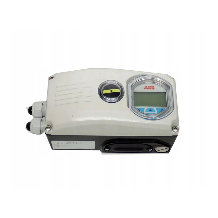
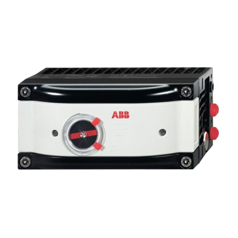
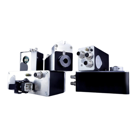
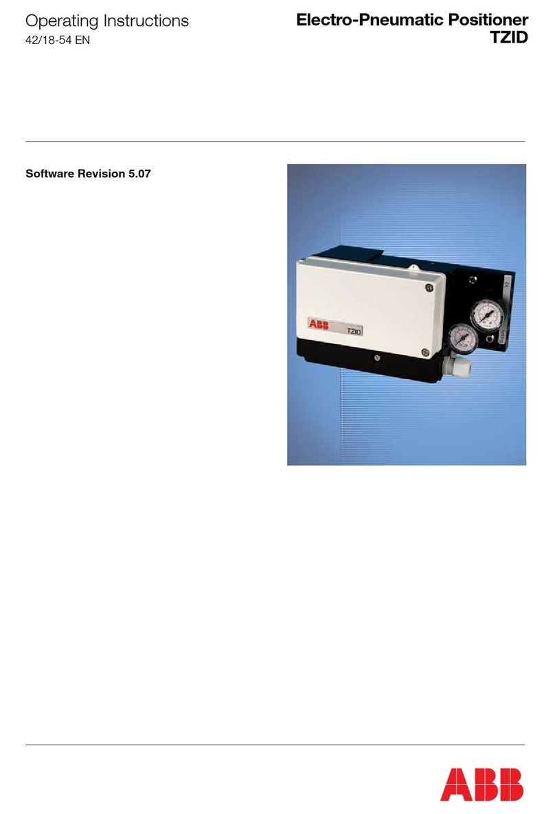
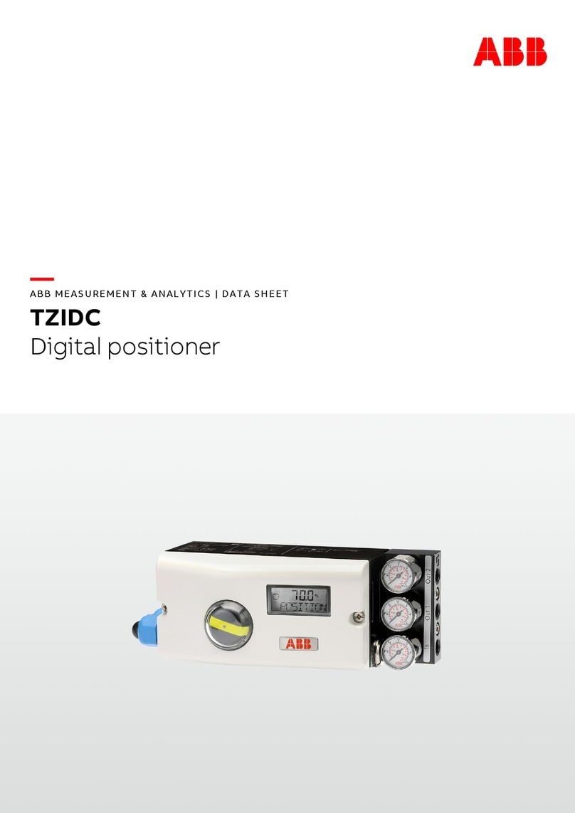
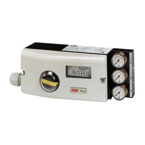
ABB TZIDC User manual

—
ABB MEASUREMENT & ANALYTICS |
TECHNICAL DESCRIPTION | TD/ZIDC/TZIDC-200/NON-CONTACT_SENSOR-EN REV. A
TZIDC,
TZIDC-200
Digital positioner
—
ABB Measurement & Analytics
For your local ABB contact, visit:
www.abb.com/contacts
For more product information, visit:
www.abb.com/positioners
Technical description for manual
configuration of the contactless
360° sensor.
TD/TZIDC/TZIDC
-200/NON-CONTACT_SENSOR-EN Rev. A 08.2023
—
TZIDC
TZIDC
-200
Introduction
Devices from HW rev.: 5.01 can be equipped with
the order option “Contactless position
feedback”.
The position feedback then takes place via a 360°
sensor without mechanical end stops.
This allows a wider operating range of up to 350°.
The operating range can then be at any point in
the sensor range.
If the device's installation situation is different
from the standard described in the operating
instructions, such as gear rack actuators, further
parameter settings will be required.
The parameter settings are described in this
Technical description
.
Additional Information
Additional documentation on
TZIDC, TZIDC-200 is
available for download free of charge at
www.abb.com/
positioners.
Alternatively simply scan this code:
—
We reserve the
right to make technical changes or modify the contents of this
document without prior
notice. W ith regard to purchase orders, the agreed particulars
shall prevail.
ABB does not accept any
responsibility whatsoever for potential errors or possible lack
of information in this document.
We reserve all rights in this document and in the
subject matter and illustrations
contained therein.
Any reproduction, disclosure to third parties or utilization of its
contents
– in whole or in parts – is forbidden without prior written consent of ABB.
© ABB 2023 3KXE341221R2901

2 TZIDC, TZIDC-200 DIGITAL POSITIONER | TD/TZIDC/TZIDC-200/NON-CONTACT_SENSOR-EN REV. A
Table of contents
1Introduction..............................................................................................3
Automatic adjustment..............................................................................................3
Area of application....................................................................................................3
2Manual configuration of end positions..................................................4
Example..................................................................................................................... 4
Manual configuration of the parameters............................................................... 5
Procedure ............................................................................................................ 5

TZIDC, TZIDC-200 DIGITAL POSITIONER | TD/TZIDC/TZIDC-200/NON-CONTACT_SENSOR-EN REV. A 3
1Introduction
Automatic adjustment
The standard automatic adjustment for rotary and linear
actuators is performed as described in the operating
instructions under Standard automatic adjustment.
For different installation situations, such as gear rack actuators
or valves that do not feature mechanical restrictions or that
could be damaged when activating the end positions, the user
has to manually configure the relevant parameters during
commissioning.
The parameter settings are described in this Technical
description.
Also observe the operating instructions for the positioner.
Area of application
The configurations described in this Technical description apply
only to digital positioner TZIDC / TZIDC-200 from HW-REV.:
05.01.xx and order option “S1 – Contactless sensor”.

4 TZIDC, TZIDC-200 DIGITAL POSITIONER | TD/TZIDC/TZIDC-200/NON-CONTACT_SENSOR-EN REV. A
2Manual configuration of end positions
Example
The following figure is a sample depiction of the operating range
of a TZIDC, TZIDC-200 after the parameters for the contactless
sensor in the positioner have been configured manually.
The following initial situation is assumed:
• The actuator uses spring force or ventilation to move
clockwise from OUT2 to an opening degree of 0%.
In order for the operating range of the positioner
(P6.0–MIN_VR, P6.1–MAX_VR) to be fully defined, the parameters
P6.7–ZERO_POS and
P6.3–SPRNG_Y2 must additionally be positioned toward the
relevant rotational direction during commissioning.
In this case, it applies to the following configurations:
• P6.7 (ZERO_POS) = CLOCKWISE (Figure 1, Pos. E)
• P6.3 (SPRNG_Y2) = CLOCKWISE (Figure 1, Pos. D)
Note
Depending on the relevant installation situation, the parameters
must always be determined and configured individually on site.
1
Device feedback shaft
2
Lever
A
Operating range 100% opening degree, OUT1 = supply pressure
B
Operating range 0% opening degree, OUT1 = ambient pressure
C
Operating range of the valve/actuator, parameter “P6.0 – MIN_VR” and “P6.1 – MAX_VR”.
For rotary actuators, the operating range within each position can be up to 340°.
D
Rotational direction for parameter “P6.3 – SPRNG_Y2 = CLOCKWISE” (When venting OUT 1, the device feedback shaft 1turns clockwise).
E
Rotational direction for parameter “P6.7 – ZERO_POS = CLOCKWISE” (When venting OUT 1, the device feedback shaft 1turns clockwise).
Figure 1: Measurement and operating range with contactless position feedback (example)

TZIDC, TZIDC-200 DIGITAL POSITIONER | TD/TZIDC/TZIDC-200/NON-CONTACT_SENSOR-EN REV. A 5
Manual configuration of the parameters
Note
For detailed information on the parameterization, consult the
separate configuration and parameterization instructions
“COI/TZIDC/TZIDC-200”.
The following parameters must be configured:
Parameter
Description
Selection of actuator type
• ROTARY: Part-turn actuator
• LINEARY: Linear actuator
Operating range end position minimum
Operating range end position maximum
Rotational direction of the spring effect or
rotational direction at OUT2 under pressure.
• CLOCKWISE: Rotational direction clockwise
• CTCLOCKWISE: Rotational direction
counterclockwise
Rotational direction to reach 0% position of the
actuator.
• CLOCKWISE: Rotational direction clockwise
• CTCLOCKWISE: Rotational direction
counterclockwise
NOTICE
Damage of actuators / valves or impairment of the regulator
function
In cases of incorrect parameterization, in particular of
parameter P6.3 (SPRNG_Y2) and P6.7 (ZERO_POS), damage to
actuators/valves or an impairment of the regulator function
may occur.
• Ensure that the configuration of parameters is performed
in accordance with the following method.
Procedure
1. Activate the safety position via parameter P11.0 (FAIL_POS).
2. Reset the positioner via parameter P11.1 (FACT_SET) to the
factory setting.
3. Save the changes via parameter P11.5 (EXIT) in the non-
volatile memory.
4. Select the actuator type via parameter P6.2 (ACTUATOR).
• ROTARY: Rotary actuator or gear rack actuator.
• LINEARY: Linear actuator
5. Select parameter P6.0 (MIN_VR).
• Move the actuator by pressing the button to the 0%
position (OUT1 depressurized).
• Press and hold the ENTER button until the countdown is
finished (MIN_SET). The position is copied as MIN_VR.
• Briefly press the ENTER button. The set limit value is
displayed for 2 seconds (MIN_SAVE).
• Note the rotational direction
(clockwise/counterclockwise) of the actuator and
whether the actuator rotates into the 0% direction
(yes/no).
6. Select parameter P6.1 (MAX_VR).
• Move the actuator by pressing the button to the 100%
position (OUT2 depressurized).
• Press and hold the ENTER button until the countdown is
finished (MAX_SET). The position is copied as MAX_VR.
• Briefly press the ENTER button. The set limit value is
displayed for 2 seconds (MAX_SAVE).
7. Select parameter P6.7(ZERO_POS).
• If the actuator is moved into the 0% position when
configuring P6.0 (MIN_VR), position the parameter in the
relevant rotational direction (CLOCKWISE /
CTCLOCKWISE).
8. Select parameter P6.3(SPRNG_Y2).
• Now position the parameter in the rotational direction
determined during the configuration of P6.0 (MIN_VR)
(CLOCKWISE / CTCLOCKWISE).
9. Select parameter P6.8 (EXIT) to return to the operational
level.
• Select NV_SAVE to save the configurations in the non-
volatile memory.
• Select CANCEL to reject the configurations in the non-
volatile memory.
10. Check the activation of the actuator. If the control behavior is
incorrect, check the parameterization in accordance with
these instructions and perform it again if required.
6 TZIDC, TZIDC-200 DIGITAL POSITIONER | TD/TZIDC/TZIDC-200/NON-CONTACT_SENSOR-EN REV. A
Notes

TZIDC, TZIDC-200 DIGITAL POSITIONER | TD/TZIDC/TZIDC-200/NON-CONTACT_SENSOR-EN REV. A 7
Notes

—
ABB MEASUREMENT & ANALYTICS |
TECHNICAL DESCRIPTION | TD/ZIDC/TZIDC-200/NON-CONTACT_SENSOR-EN REV. A
TZIDC,
TZIDC-200
Digital positioner
—
ABB Measurement & Analytics
For your local ABB contact, visit:
www.abb.com/contacts
For more product information, visit:
www.abb.com/positioners
Technical description for manual
configuration of the contactless
360° sensor.
TD/TZIDC/TZIDC
-200/NON-CONTACT_SENSOR-EN Rev. A 08.2023
—
TZIDC
TZIDC
-200
Introduction
Devices from HW rev.: 5.01 can be equipped with
the order option “Contactless position
feedback”.
The position feedback then takes place via a 360°
sensor without mechanical end stops.
This allows a wider operating range of up to 350°.
The operating range can then be at any point in
the sensor range.
If the device's installation situation is different
from the standard described in the operating
instructions, such as gear rack actuators, further
parameter settings will be required.
The parameter settings are described in this
Technical description
.
Additional Information
Additional documentation on
TZIDC, TZIDC-200 is
available for download free of charge at
www.abb.com/
positioners.
Alternatively simply scan this code:
—
We reserve the
right to make technical changes or modify the contents of this
document without prior
notice. W ith regard to purchase orders, the agreed particulars
shall prevail.
ABB does not accept any
responsibility whatsoever for potential errors or possible lack
of information in this document.
We reserve all rights in this document and in the
subject matter and illustrations
contained therein.
Any reproduction, disclosure to third parties or utilization of its
contents
– in whole or in parts – is forbidden without prior written consent of ABB.
© ABB 2023 3KXE341221R2901
Other manuals for TZIDC
13
This manual suits for next models
1
Table of contents
Other ABB Valve Positioner manuals

ABB
ABB TZIDC Original operating manual

ABB
ABB TZIDC User manual

ABB
ABB AV3 User manual

ABB
ABB TZIDC User manual

ABB
ABB TZIDC-200 User manual

ABB
ABB TZIDC Installation and operation manual

ABB
ABB TZIDC User manual

ABB
ABB TZIDC-220 User manual

ABB
ABB TZIDC User manual

ABB
ABB HART Industrial IT enabled TZIDC User manual