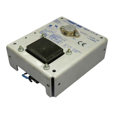
Power One SFP450 Series Owner's manual

All rightsstrictlyreserved. Reproductionor issuetothird partiesinanyformisnot permitted without written authority fromPower-One.
Title Issued 2006-05-19 SKl
Modified -- --
Mech. Eng. approved -- --
Marketing approved
SFP450/600 I2CInterfaceProgramming
Manual
Mfg. approved --
Size Scale Sheet Drawing No. Revision
www.power-one.com A4 1/21 BBA20005-G 001
Supersedes: -
SFP450/600I2CInterface ProgrammingManual
1Scope
This documentdescribesin detail theI2Ccommunication interfaceoftheSFP450/600 series. (SFP450-,
SFP600, ….)This includes thephysicallayerand theSWprotocol.
2SFP450/600I2CInterface GeneralCharacteristic
SFP450/600 I2Cinterfaceslave
I2CDeviceAddressingFormat 7bit
Device Address Range ACHex...AFHex, 7FHex,7DHex
Max. SFP450/600 on oneI2CBus 2
MaximumI2Cclock 100kHz
MaximumI2Cclock withoutholdingtheSCLlinedown SerialEEPROM:
Status Port: 100kHz
6.5kHz
Pull-Up Voltage 3.3…4V
SDA/SCLinternalseriesresistors 100
InternalPull-Up 10k
InternalPull-Up voltage 3.3V
Internalcapacitance 140pF
InternalPull-Up Address lines 3.2k
InternalPull-Up Address lines voltage 3V
InternalPull-Up WriteProtect 4.7k
Recommended externalPull-Up forSDA and SCL 1.2k …2k
DataOrganization -SerialEEPROM(256 x 8bit)
-Status Port withcommands
Figure 2-1 Characteristic

All rightsstrictlyreserved. Reproductionor issuetothird partiesinanyformisnot permitted without written authority fromPower-One.
Title Issued 2006-05-19 SKl
Modified -- --
Mech. Eng. approved -- --
Marketing approved
SFP450/600 I2CInterfaceProgramming
Manual
Mfg. approved --
Size Scale Sheet Drawing No. Revision
www.power-one.com A4 2/21 BBA20005-G 001
Supersedes: -
3Index
1Scope......................................................................................................................................................1
2SFP450/600 I2CInterfaceGeneralCharacteristic.................................................................................1
3Index......................................................................................................................................................2
4SFP450/600 I2Cfeatures........................................................................................................................3
4.1 Dynamicdata.................................................................................................................................3
4.2 Staticdata.......................................................................................................................................3
4.3 ConnectingtheSFP450/600 to theI2CBus...................................................................................4
4.4 SFP450/600 I2CSupply(Slave)....................................................................................................5
4.5 Device Address..............................................................................................................................5
4.6 I
2
CBus Masterand clock (SCL)speed.........................................................................................6
4.7 Maximumand minimumvalues forPull-Up resisters...................................................................6
5SWProtocol...........................................................................................................................................7
5.1 StaticserialEEPROM data............................................................................................................7
5.1.1 Howto Read an EEPROM byte............................................................................................8
5.1.2 Howto readan EEPROM datablock....................................................................................9
5.1.3 Howto writean EEPROM byte..........................................................................................10
5.1.4 Power OneEEPROM Definitions.......................................................................................11
5.1.4.1 Timestamp.......................................................................................................................11
5.1.4.2 Checksum32.....................................................................................................................11
5.2 DynamicStatus PortData............................................................................................................12
5.2.1 Status Bytedefinition...........................................................................................................13
5.2.2 Voltage/currentdatainterpretation......................................................................................13
5.2.3 Howto read thestatus bytefromStatus Port.......................................................................14
5.2.4 Howto read themeasured outputVoltage/Current.............................................................15
5.3 ErrorHandling.............................................................................................................................16
5.3.1 Read Byte.............................................................................................................................16
5.3.2 Read StaticserialEEPROM................................................................................................17
5.3.3 Read Status Port...................................................................................................................18
6Power-OneI2CInterface tool..............................................................................................................19
7Bibliography........................................................................................................................................21
8Figure Index.........................................................................................................................................21
9Glossary...............................................................................................................................................21

All rightsstrictlyreserved. Reproductionor issuetothird partiesinanyformisnot permitted without written authority fromPower-One.
Title Issued 2006-05-19 SKl
Modified -- --
Mech. Eng. approved -- --
Marketing approved
SFP450/600 I2CInterfaceProgramming
Manual
Mfg. approved --
Size Scale Sheet Drawing No. Revision
www.power-one.com A4 3/21 BBA20005-G 001
Supersedes: -
4SFP450/600I2Cfeatures
4.1 Dynamicdata
TheSFP450/600 series supports followingmonitoringfeatures:
-Measured Output1 voltage[V]
-Measured Output1 current[A]
-Power Supplyseated/notseated
-InputVoltagein range/outofrange
-All OutputVoltagein range/outofrange
-Output1 over currentoccurred true/false
-Output1 and 2 under voltageoccurred true/false
-Output1 over voltageoccurredtrue/false
-Fan OK/failure
-Over Temperaturetrue/false
4.2 Staticdata
In theEEPROM are followingstaticdatastored:
-Power SupplyModel
-SerialNumber
-Power-OneRevision
-MFG Year
-MFG Month
-MFG Day
-MFG Name
-MFG Location Code
-Specified Output1 Voltage
-Specified Output2 Voltage
-Specified Output1 Current
-Specified Output2 Current
-Specified OutputPower
-MinimumSpecified InputVoltage
-MaximumSpecified InputVoltage
-xx BytesEEPROM for Customer use
-Spec Number
-TimeStamp
-Sequential Nr
-Checksumover static range

All rightsstrictlyreserved. Reproductionor issuetothird partiesinanyformisnot permitted without written authority fromPower-One.
Title Issued 2006-05-19 SKl
Modified -- --
Mech. Eng. approved -- --
Marketing approved
SFP450/600 I2CInterfaceProgramming
Manual
Mfg. approved --
Size Scale Sheet Drawing No. Revision
www.power-one.com A4 4/21 BBA20005-G 001
Supersedes: -
GeneralI2CHWconfiguration
Figure 4-1 SystemOverview
4.3 Connecting theSFP450/600 to theI2CBus
Thefollowingdiagramshows howtheSFP450/600 can beconnected to theI2CBus.
Figure 4-2 Recommendedconnectingof the SFP450/600 tothe I2CBus
I
2
CBus Master
SFP450/600
SFP450/600
Other I
2
C
Devices
Oneor two
SFP450/600
:
I
2
CBus
EEPROM
+3.3VSB
:
PS A0 Pin A5
SFP450/600(I
2
CSlave)
Pin A6, B4,C4,D4 Internal supply
SDA
SCL
Pin B5
Pin C5
:
Pin A3,B1,B3,C1,C3,D3
Return
:
:
:
Address
decoder
3.3V
:
:
:
:
:
Controller
:
I
2
CMaster
To the other SFP450/600 or
3.3VSupply
I
2
C Bus
1
3
2
1
External Pull-Up
2
SDA/SCLinternal Pull-Up
3
SDA/SCLinternal series resistors
:
3V
Ref
.
Micro
controller
(Status Port)
:
:
:
:
:
:
:
:
:
:
:
5
4
4
5
SDA/SCLinternal capacitance
Internal Pull-UpAddress lines
Write Protect
Pin A4
:
:
6
6
Internal Pull-UpWrite Protect

All rightsstrictlyreserved. Reproductionor issuetothird partiesinanyformisnot permitted without written authority fromPower-One.
Title Issued 2006-05-19 SKl
Modified -- --
Mech. Eng. approved -- --
Marketing approved
SFP450/600 I2CInterfaceProgramming
Manual
Mfg. approved --
Size Scale Sheet Drawing No. Revision
www.power-one.com A4 5/21 BBA20005-G 001
Supersedes: -
4.4 SFP450/600 I2CSupply(Slave)
TheSFP450/600 MicroController/EEPROM is powered over theinternalsupplyoftheSFP450/600. For
redundancyincaseofDCfailure orSFP450/600 internalfailure theSFP450/600 Micro
Controller/EEPROM can bepowered over the“+3.3VSB”(Pin A6, B4,C4,D4 ;3.3V).Ifthere is no power
fortheSFP450/600 Micro Controller theentire I2CBus is blocked.
4.5 Device Address
Thefirstbyteafter theSTARTcondition on theBus isthedevice addresssentoutbytheBus Master to
determinewhich deviceisbeingselected. TheI2CBus allows7-bit or10-bit addressing. TheSFP450/600
Interface usesa7-bit address modeasdefinedinthePhilips I²Cspecification. TheSFP450/600 contains
anEEPROMand aSTATUS(microcontroller) device and eachdevice ontheI2CBus hastobeassigned
to auniqueaddress.
As shown belowin Error! Reference sourcenotfound.theaddress byteisbuilt up fromthree parts:
-Bit 2...7:Thesebits arealways thesameindependentofanyaddress line.
-Bit 1:This bit depends howtheAddress lineA0is connected on thebackplaneon theaddress
decoder.Theseare logic1 ifopen and logic0 ifwired to 0V(Return).
-Bit 0:Thisbitistheread/writebit (R=1/W=0)and determinesthedirection ofthedatafromortothe
Master.
MSB LSB
Bit 7 6 5 4 3 2 1 0
SFP450/600-S102
EEPROM
Device Address
1 0 1 0 1 1 PS A0 direc
fix fix fix fix fixfix addr.
line R/W
SFP450/600-S102
STATUS
Device Address
0 1 1 1 1 1 PS A0 direc
fix fix fix fix fix fix addr.
line R/W
Figure 4-3 Device Address
Address
Line
PS A0
Read/
Write Device
Address
[Bin]
Device
Address
[Hex]
Device
Address
[Dec]
SFP450/600EEPROM Deviceaddress open read 1010’1111 AF 175
SFP450/600EEPROM Deviceaddress open write 1010’1110 AE 174
SFP450/600STATUS Deviceaddress open Read 0111’1111 7F 127
SFP450/600EEPROM Deviceaddress 0V read 1010’1101 AD 173
SFP450/600EEPROM Deviceaddress 0V Write 1010’1100 AC 172
SFP450/600STATUS Deviceaddress 0V Read 0111’1101 7D 125
Figure 4-4 Device Address Table

All rightsstrictlyreserved. Reproductionor issuetothird partiesinanyformisnot permitted without written authority fromPower-One.
Title Issued 2006-05-19 SKl
Modified -- --
Mech. Eng. approved -- --
Marketing approved
SFP450/600 I2CInterfaceProgramming
Manual
Mfg. approved --
Size Scale Sheet Drawing No. Revision
www.power-one.com A4 6/21 BBA20005-G 001
Supersedes: -
Example:On thebackplanePS A0 is connected to0V,you will havethefollowingdeviceaddress to read
abytefromtheSFP450/600 EEPROM:
MSB LSB
Bit 7 6 5 4 3 2 1 0
SFP450/600
EEPROM
Device Address
1 0 1 0 1 1 0 1
fix fix fix fix fix fix A0 R
->1010’1101Bin=ADHex=173Dec
4.6 I2CBus Master and clock(SCL)speed
TheI2CBusMastercontrolscommunications betweentheMasterandallI2Cdevicesconnectedtothe
bus. IfduringanI
2
Ccommunication cycletheSFP450/600 Status Portisinterruptedbyaninternal
service interrupt,theSFP450/600 will holdtheSCLlinelowtoforcethemaster intoawait state.Data
transferwill continuewhentheSFP450/600 releasestheSCLline.PleasenoteiftheI
2
Cbus is
communicatingwithaclockfrequencyslower than6.5kHz,theSCLlinewill notbeheldlow.The
SFP450/600 EERPOM isan ATMELAT24C02 compatibledevice and is notholdingdown theSCLline.
4.7 Maximumand minimumvalues forPull-Upresisters
ForI2C-bus systems, thevalues ofthePull-Up resistors depend on thefollowingparameters:
• Supplyvoltage
• Bus capacitance
• Number ofconnected devices (inputcurrent+leakagecurrent).
ThesupplyvoltagelimitstheminimumvalueofthePull-Upresistorduetothespecifiedminimumsink
currentof3mA. On a3.3Vsupply, this makes Rmin=3.3V/3mA=1.1k .
Thebus capacitanceis thetotalcapacitance ofwire, connections and pins. This capacitance limits the
maximumvalueofthePull-Upresisterduetothespecifiedrisetime.ForaSystemwith380pF
capacitance (two SFP450/600 and awire capacitance of100pf) Rmax=2.1k .
Forfurther information concerningthePull-Up resister, referto:
I²C Busspecification, 16.1Maximumand minimumvaluesofresistorsRpand Rsfor Standard-mode I2C-busdevices.

All rightsstrictlyreserved. Reproductionor issuetothird partiesinanyformisnot permitted without written authority fromPower-One.
Title Issued 2006-05-19 SKl
Modified -- --
Mech. Eng. approved -- --
Marketing approved
SFP450/600 I2CInterfaceProgramming
Manual
Mfg. approved --
Size Scale Sheet Drawing No. Revision
www.power-one.com A4 7/21 BBA20005-G 001
Supersedes: -
5SW Protocol
Thestaticdataare storedin aserialI2CEEPROMand thedynamicdatacan berequested over theStatus
Portwith three commands.
5.1 StaticserialEEPROMdata
Therefore each EEPROM address has defined data;this definition is documented in thefile:
104718_xxx.pdf, 104788_xxx.pdf
Dez
Hex
Address 0
staticdata 0
1
staticdata 1
251
staticdata FB
252
checksum FC
253
checksum FD
254
checksum FE
255
checksumFF
Figure 5-1: Data Organization
There are three differentmessageformats fortheSFP450/600 SerialEEPROM:
-Read an EEPROM byte
-Read an EEPROM block
-Writean EEPROM byte

All rightsstrictlyreserved. Reproductionor issuetothird partiesinanyformisnot permitted without written authority fromPower-One.
Title Issued 2006-05-19 SKl
Modified -- --
Mech. Eng. approved -- --
Marketing approved
SFP450/600 I2CInterfaceProgramming
Manual
Mfg. approved --
Size Scale Sheet Drawing No. Revision
www.power-one.com A4 8/21 BBA20005-G 001
Supersedes: -
5.1.1 Howto ReadanEEPROMbyte
1)"Startcondition"fromMaster
2)Master sends "Device address"with "writeattribute"
3)"Acknowledge"fromSlavedevice (SFP450/600)
4)Master sends "EEPROM address"
5)"Acknowledge"fromSlavedevice (SFP450/600)
6)"Repeated start"fromMaster (Sr/S)
7)Master sends "Device address"with "read attribute"
8)"Acknowledge"fromSlavedevice (SFP450/600)
9)Slavesends "Databyte"
10)"NotAcknowledge"fromMaster (powermanagementsystem)
11)"Stop condition"fromMaster
Master
Slave(SFP450/600 EEPROM)
S
Slave
Adr. W
AEEPROM
Adr. A
Sr/S
Slave
Adr. R
A
DataByte
/A
P
8bit 8 bit 8bit 8 bit
Start
Condition
n
ot Ack
bit
Ack bit
Ack bit Ack bit Stop
Condition
Start
Condition

All rightsstrictlyreserved. Reproductionor issuetothird partiesinanyformisnot permitted without written authority fromPower-One.
Title Issued 2006-05-19 SKl
Modified -- --
Mech. Eng. approved -- --
Marketing approved
SFP450/600 I2CInterfaceProgramming
Manual
Mfg. approved --
Size Scale Sheet Drawing No. Revision
www.power-one.com A4 9/21 BBA20005-G 001
Supersedes: -
5.1.2 Howto readanEEPROMdata block
1)"Startcondition"fromMaster
2)Master sends "Device address"with "writeattribute"
3)"Acknowledge"fromSlavedevice (SFP450/600-S102)
4)Master sends "EEPROM address"
5)"Acknowledge"fromSlavedevice (SFP450/600-S102)
6)"Repeated start"fromMaster (Sr/S)
7)Master sends "Slaveaddress"with"read attribute"
8)"Acknowledge"fromSlavedevice (SFP450/600-S102)
9)Slavesends "Databyte"
10)"Acknowledge"fromMaster (powermanagementsystem)
n-timerepetition ofstep9)and 10)
11)Slavesends "Databyte"
12)"NotAcknowledge"fromMaster (powermanagementsystem)
13)"Stop condition"fromMaster
S SlaveAdr. W
A EEPROM Adr. A Sr/S SlaveAdr. R A DataByte A
8 bit 8 bit 8bit 8 bit
…. ….
Master
Slave(SFP450/600 EERPOM)
DataByte A
8bit DataByte /A P
8 bit
StartCondition Ack bit
Ack bit Ack bit
Ack bit
Stop
Condition
not Ack bit
Ack bit
StartCondition

All rightsstrictlyreserved. Reproductionor issuetothird partiesinanyformisnot permitted without written authority fromPower-One.
Title Issued 2006-05-19 SKl
Modified -- --
Mech. Eng. approved -- --
Marketing approved
SFP450/600 I2CInterfaceProgramming
Manual
Mfg. approved --
Size Scale Sheet Drawing No. Revision
www.power-one.com A4 10/21 BBA20005-G 001
Supersedes: -
5.1.3 Howto write anEEPROMbyte
1)Pull down theWriteProtectline(Pin A4)
2)"Startcondition"fromMaster
3)Master sends "Slaveaddress"with "writeattribute"
4)"Acknowledge"fromSlavedevice (SFP450/600)
5)Master sends "EEPROM address"
6)"Acknowledge"fromSlavedevice (SFP450/600)
7)Master sends "Databyte"
8)"Acknowledge"fromSlavedevice (SFP450/600)
9)"Stop condition"fromMaster
10)ReleasetheWriteProtectline(Pin A4)
11)Wait 5ms forthenextEEPROM communication (EEPROM writetime)
Master
Slave(SFP450/600 EEPROM)
WP S
Slave
Adr. W
A
EEPROM
Adr. A
Data
Byte A
P WP↑
8 bit 8 bit 8bit
Ack bit
Ack bit Ack bit Stop
Condition
Start
Condition
ReleaseWrite
Protect line
Pull downWrite
Protect line

All rightsstrictlyreserved. Reproductionor issuetothird partiesinanyformisnot permitted without written authority fromPower-One.
Title Issued 2006-05-19 SKl
Modified -- --
Mech. Eng. approved -- --
Marketing approved
SFP450/600 I2CInterfaceProgramming
Manual
Mfg. approved --
Size Scale Sheet Drawing No. Revision
www.power-one.com A4 11/21 BBA20005-G 001
Supersedes: -
5.1.4 Power OneEEPROMDefinitions
5.1.4.1 Timestamp
TheUNIXtimestamp isa32-bit big-endian integer thatrepresents thenumber ofseconds since January1,
1970 at00:00:00 UTC(GMT).
Byte220
Bits Bit 7
Bit 6
Bit 5
Bit 4
Bit 3
Bit 2
Bit 1
Bit 0
Valueofthebit 231 230 229 228 227 226 225 224
Seconds Value x x x x x x x x
Byte221
Bits Bit 7
Bit 6
Bit 5
Bit 4
Bit 3
Bit 2
Bit 1
Bit 0
Valueofthebit 223 222 221 220 219 218 217 216
Seconds Value x x x x x x x x
Byte222
Bits Bit 7
Bit 6
Bit 5
Bit 4
Bit 3
Bit 2
Bit 1
Bit 0
Valueofthebit 215 214 213 212 211 210 2928
Seconds Value x x x x x x x x
Byte223
Bits Bit 7
Bit 6
Bit 5
Bit 4
Bit 3
Bit 2
Bit 1
Bit 0
Valueofthebit 2726252423222120
Seconds Value x x x x x x x x
Figure 2 TableforTimestamp
5.1.4.2 Checksum32
Checksum32 is calculated fromfield 220 to 251.

All rightsstrictlyreserved. Reproductionor issuetothird partiesinanyformisnot permitted without written authority fromPower-One.
Title Issued 2006-05-19 SKl
Modified -- --
Mech. Eng. approved -- --
Marketing approved
SFP450/600 I2CInterfaceProgramming
Manual
Mfg. approved --
Size Scale Sheet Drawing No. Revision
www.power-one.com A4 12/21 BBA20005-G 001
Supersedes: -
5.2 DynamicStatus Port Data
TheI2CMastercanreadfromthestatus portthestatus ofthePS, themeasured voltageand current.There
existthree commands.
0x01:read status byte
0x02:read measured voltage
0x03:read measured current
send StatusByte send high byte,
measuredVoltage
send lowbyte,
measuredVoltage
send high byte,
measured current
send lowbyte,
measured current
Reset or0x01 command
0x02 command
read port
0x03 command
read port
Figure 3Software statesforthe Statusport

All rightsstrictlyreserved. Reproductionor issuetothird partiesinanyformisnot permitted without written authority fromPower-One.
Title Issued 2006-05-19 SKl
Modified -- --
Mech. Eng. approved -- --
Marketing approved
SFP450/600 I2CInterfaceProgramming
Manual
Mfg. approved --
Size Scale Sheet Drawing No. Revision
www.power-one.com A4 13/21 BBA20005-G 001
Supersedes: -
5.2.1 Status Byte definition
Explanation
Bit 0 PSpresent= 0(True) False= 1 ThisSignal indicatesthat thePSispresent.
Bit 1 PWOK = 1(PSOK) Fault = 0
OutputPower Good, signalizedthat all outputs
arevalid.
Bit 2 ACOK = 0(OK) Fault = 1 ACinspecifiedrange.
Bit 3 OC+12V= 1(PSOK) Fault = 0 +12 VOver Currentgoeslowwhenit exceeds
thecurrentrating. Theoutputwillbelatched.*
Bit 4 UV+12V,UV+3V3SBY= 1
(PSOK) Fault = 0 +12VUnder Voltagegoeslow,when+12V
dipsunder thespecifiedvoltageandshuts
downtheUnit. TheOutputwill belatched.*
Or the3.3VSBYhasanUnder Voltage.
Bit 5 OV +12V= 1(PSOK) Fault = 0 +12VOver Voltagegoeslow, when+12V
tripsover thespecifiedvoltageandshutsdown
theunit. TheOutputwill belatched.*
Bit 6 ALERT= 1(PSOK) Fault = 0 TheAlertsignalgoeshigh, ifoneofthefans
fallsbelowathresholdspeedvalueor anOTP
occurs.
Bit 7 OTP= 1(PSOK) Fault=0 TheOver TemperatureProtectioncircuit has
shutdowntheunit.
Tableforstatus information
*Latched statescan onlybecleared byrecyclingACmains ortogglingPS_ON.
5.2.2 Voltage/currentdata interpretation
Thevoltageand currentmonitorcan beaccessedwith thecommands 0x02and 0x03. Thevalues are
returned in an unsigned 10bit number which is leftjustified. Forthevoltagemeasuringtheresolutionis
20mV/bit and forthecurrentresolution is 50mA/bit.
Exampleofavoltagemeasuring:
Bit 7 Bit 0 Bit 7 Bit 0
1 0 0 1 0 1 1 0 0 0 x x x x
Firstbyte1 Second byte
This gives thevalue:10’0101’1000BIN =258HEX=600DEZ
Themeasured voltageis600DEZ *20mV/bit=12000 mV
70
MS firstread
76
LS 50
Secondread
10bitvalue

All rightsstrictlyreserved. Reproductionor issuetothird partiesinanyformisnot permitted without written authority fromPower-One.
Title Issued 2006-05-19 SKl
Modified -- --
Mech. Eng. approved -- --
Marketing approved
SFP450/600 I2CInterfaceProgramming
Manual
Mfg. approved --
Size Scale Sheet Drawing No. Revision
www.power-one.com A4 14/21 BBA20005-G 001
Supersedes: -
5.2.3 Howto readthestatus byte fromStatus Port
To read thestatus byte, islikereadingfromaserialEEPROM ataddress 0x01.
1)"Startcondition"fromMaster
2)Master sends "Status PortDevice address"with "writeattribute"
3)"Acknowledge"fromSlavedevice (SFP450/600 Status Port)
4)Master sends "Status Portcommand address 01"
5)"Acknowledge"fromSlavedevice (SFP450/600 Status Port)
6)"Repeated start"fromMaster (Sr/S)
7)Master sends "Status Portdevice address"with "read attribute"
8)"Acknowledge"fromSlavedevice (SFP450/600 Status Port)
9)Slavesends "Status byte"
10)"NotAcknowledge"fromMaster (powermanagementsystem)
11)"Stop condition"fromMaster
Master
Slave(SFP450/600 Status Port)
S
Slave
Adr. W
ACommand
01HEX A
Sr/S
Slave
Adr. R
A
Status Byte
/A
P
8bit 8 bit 8bit 8 bit
Start
Condition
not Ack
bit
Ack bit
Ack bit Ack bit Stop
Condition
Start
Condition

All rightsstrictlyreserved. Reproductionor issuetothird partiesinanyformisnot permitted without written authority fromPower-One.
Title Issued 2006-05-19 SKl
Modified -- --
Mech. Eng. approved -- --
Marketing approved
SFP450/600 I2CInterfaceProgramming
Manual
Mfg. approved --
Size Scale Sheet Drawing No. Revision
www.power-one.com A4 15/21 BBA20005-G 001
Supersedes: -
5.2.4 Howto readthemeasuredoutputVoltage/Current
1)"Startcondition"fromMaster
2)Master sends "Status PortDevice address"with "writeattribute"
3)"Acknowledge"fromSlavedevice (SFP450/600 Status Port)
4)Master sends "Command 02 (Voltage) or03(Current)"
5)"Acknowledge"fromSlavedevice (SFP450/600 Status Port)
6)"Repeated start"fromMaster (Sr/S)
7)Master sends "Status PortDevice address"with "read attribute"
8)"Acknowledge"fromSlavedevice (SFP450/600 Status Port)
9)Slavesends "firstdataByte"
8)"Acknowledge"fromMaster (powermanagementsystem)
9)Slavesends "second dataByte"
10)"NotAcknowledge"fromMaster (powermanagementsystem)
11)"Stop condition"fromMaster
Master
Slave(SFP450/600 Status Port)
S
Slave
Adr. W
ACommand
02HEX or03HEX A
Sr/S
Slave
Adr. R
A
First
Byte
A Second
Byte /A
P
8bit 8 bit 8bit 8 bit 8 bit
Start
Condition
not Ack
bit
Ack bit
Ack bit Ack bit Stop
Condition
Start
Condition Ack bit

All rightsstrictlyreserved. Reproductionor issuetothird partiesinanyformisnot permitted without written authority fromPower-One.
Title Issued 2006-05-19 SKl
Modified -- --
Mech. Eng. approved -- --
Marketing approved
SFP450/600 I2CInterfaceProgramming
Manual
Mfg. approved --
Size Scale Sheet Drawing No. Revision
www.power-one.com A4 16/21 BBA20005-G 001
Supersedes: -
5.3 ErrorHandling
Errors in thecommunication can occur. Thefollowingflowchartshows howtheBus Mastercan handle
such errors.
5.3.1 ReadByte
start
set startcondition
senddeviceadr. /w
get acknolage
setstopcondition
set startcondition
senddeviceadr./r
get acknolage
recivedata
sendno acknolage
setstopcondition
end
Sendinternal
EEPROMAdr.
get acknolage
Sendstop
condition
yes
yes
yes
no
no
no
0..n

All rightsstrictlyreserved. Reproductionor issuetothird partiesinanyformisnot permitted without written authority fromPower-One.
Title Issued 2006-05-19 SKl
Modified -- --
Mech. Eng. approved -- --
Marketing approved
SFP450/600 I2CInterfaceProgramming
Manual
Mfg. approved --
Size Scale Sheet Drawing No. Revision
www.power-one.com A4 17/21 BBA20005-G 001
Supersedes: -
5.3.2 ReadStaticserialEEPROM
Start
All Bytes read
no
checksumok?
End
yes
yes
no
Read next
EEPROM
Byte
Read first
Bytefrom
EEPROM

All rightsstrictlyreserved. Reproductionor issuetothird partiesinanyformisnot permitted without written authority fromPower-One.
Title Issued 2006-05-19 SKl
Modified -- --
Mech. Eng. approved -- --
Marketing approved
SFP450/600 I2CInterfaceProgramming
Manual
Mfg. approved --
Size Scale Sheet Drawing No. Revision
www.power-one.com A4 18/21 BBA20005-G 001
Supersedes: -
5.3.3 ReadStatus Port
To besure thatthere are no corruptdata,you haveto read thedatatwice.
Start
read Status
Port
information
read Status
Port
information
first datasame
as second?
End
yes
no

All rightsstrictlyreserved. Reproductionor issuetothird partiesinanyformisnot permitted without written authority fromPower-One.
Title Issued 2006-05-19 SKl
Modified -- --
Mech. Eng. approved -- --
Marketing approved
SFP450/600 I2CInterfaceProgramming
Manual
Mfg. approved --
Size Scale Sheet Drawing No. Revision
www.power-one.com A4 19/21 BBA20005-G 001
Supersedes: -
6Power-One I2CInterface tool
ThePower-OneI2C– ManagementSoftware (HZZ02002SW, www.power-one.com) demonstratesall the
I2Cinterface features oftheSFP450/600.
Figure 6-1 Screenshot SFP450/600
Power-OneI2C– ManagementSoftware supports twoI2Cconverters:
iPortMIIC-201 (Micro Computer Control)HZZ02002GfromPower-One

All rightsstrictlyreserved. Reproductionor issuetothird partiesinanyformisnot permitted without written authority fromPower-One.
Title Issued 2006-05-19 SKl
Modified -- --
Mech. Eng. approved -- --
Marketing approved
SFP450/600 I2CInterfaceProgramming
Manual
Mfg. approved --
Size Scale Sheet Drawing No. Revision
www.power-one.com A4 20/21 BBA20005-G 001
Supersedes: -
Figure 6-2 HZZ02002GtoSFP450/600 cable
TheHZZ02002Ghas thePull-Up resisters connected to 5Vand 3.3Vcompatibleinputs. TheSFP450/600
has an internalclamp circuit to 4V. Connect“SDA”(pin B5), “SCL”(pinC5)and “Return”(pin
A3,B1,B3,C1,C3,D3)to theI2Cto USBconverter. Connect“PSON/L”to “Return”to enablethe
SFP450/600 and plugtheSFP450/600 to themains.
TheI2CEEPROM deviceaddress:175Dez (read)
TheI2CStatus Portdevice address:127Dez (read).
Inyourfinalapplication theI2Cmaster will beaMicroComputer oran FPGA withanI2Cinterface.That
makes it easyand inexpensiveto usetheinterface.
HZZ02002G
USBto PC
SFP450/600
ACmain
SCL
SDA
Return
D-Sub
(37 pol)
FCIPower Blade
(51721-10002406AA)
pin25
pin24
pin28
pinC5
pinB5
p
in
A3,
B1
,
B3,C1,C3,D3
:
pinB6
PSON/L
:
This manual suits for next models
3
Table of contents
Other Power One Power Supply manuals
Popular Power Supply manuals by other brands

AKO-Agrartechnik
AKO-Agrartechnik EuroGuard N 1400 operating instructions

GW Instek
GW Instek GPP-3323 user manual

Whelen Engineering Company
Whelen Engineering Company UPS69024 installation guide

Kikusui
Kikusui PAT-T Series manual

Lake Shore
Lake Shore 102 user manual

Keithley
Keithley Series 2200 quick start guide